Be sure to close the power supply isolator before disassembling the unit for repair. For repair, be sure to use the parts listed in the service parts list of the applicable unit model and. Failure to follow this warning may result in electric shock, fire and/or personal injury.).
Be sure to replace the power supply cord and power cord in case they are damaged and/or. Be sure to measure the insulation resistance after the repair work is completed, and turn on the power supply after verifying that an insulation resistance. of at least 10MΩ is achieved. Failure to follow this warning may result in injury to your hands from sharp metal or other edges.).
Improper handling of the product can result in serious personal injury or damage to property, including buildings and equipment. G Be sure to read the following safety precautions carefully before starting the maintenance work and carry out inspection and repair of the product in a safe manner.
LGH-35RX 5 -E
LGH-50RX 5 -E
LGH-65RX 5 -E
LGH-80RX 5 -E
LGH-100RX 5 -E
LGH-150RX 5 -E
LGH-200RX 5 -E
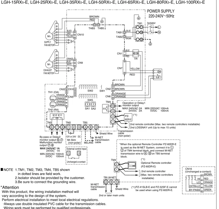
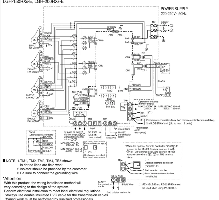
Electrical wiring diagrams
With this product, the wiring installation method will vary according to the design of the system. 2nd remote controller (Max. two remote controllers installable) 2nd LOSSNAY unit (Up to maximum 15 units).
LGH-150RX 5 -E, LGH-200RX 5 -E
- Basic circuit diagram
- Fundamentals of operation
- or PZ- 41SLB-E)
- NET transmission
Remote control: PZ-60DR-E or PZ-41SLB-E Transmission cable clamps between Lossnay unit M-NET: M-NET transmission cable. Having a remote control allows last touch priority operation with the external device and the remote control. Transmission cable between the remote control and Lossnay Lossnay remote control (PZ-60DR-E). Operation without a remote control is also possible.).
Remote control for M-NET (PZ-52SF-E). Operation without a remote control is also possible.) City Multi. Remote control : Connection block for transfer cable between PZ-60DR-E and Lossnay M-NET : M-NET transfer cable. Lossnay can be started/stopped and switched between high and low fan speed with the air conditioner remote control.
With PZ-60DR-E or PZ-52SF-E, last touch priority operation is allowed with the air conditioner remote control and the Lossnay remote control.
G-50A, AG-150ACentralized controller
NET remote controller
PAR-21MAAA-control remote controller
NET controller The system remote controller, or centralized control remote con- troller “Fan Speed” button or “Ventilation setting” button permits High
PAR-F27MEA, MA remote con-
PAR-20/21MAA
SW2-3: ON (Refer to page
38)When PZ-60DR-E will not be used in a system of
- NET controller The “Operation mode” button of the system remote con- troller and the centralized controller permits ventilation
- control remote controller K-control remote controller
Standalone/Multiple Lossnay and Lossnay Remote Control: PZ- 41SLB-E. Lossnay remote control PZ-60DR-E. The "Function Selector" button on the remote control allows ventilation mode switching for Auto, Lossnay and Bypass ventilation. Standalone/Multiple Lossnay and Lossnay Remote Control: PZ- 60DR-E. Lossnay remote control PZ-52SF-E. The "Function Selector" button on the remote control allows ventilation mode switching for Auto, Lossnay and Bypass ventilation. Standalone/Multiple Lossnay and Lossnay Remote Control: PZ- 52SF-E. M-NET Controller The “Operation Mode” button of the system remote controller and the centralized controller allows ventilation trolling and the centralized controller allows ventilation mode switching for automatic , Lossnay and bypass ventilation.
Schedule timer, ON/OFF remote control and group remote control do not allow selection of ventilation mode.). The "Function Selector" button on the remote control allows you to switch the ventilation mode for Auto, Lossnay and Bypass ventilation. When bypass ventilation has been set from the remote control or system controller, the damper operation will be set to Lossnay ventilation even though bypass ventilation is displayed on the ventilation mode screen.
Slim, or MA remote control or ME remote control for City Multi indoor units. It will switch to the ventilation mode according to the set temperature of the air conditioner remote control.
Outdoor cooling priority mode
PZ-60DR-E (Lossnay remote
SW2-2: OFF
PZ-60DR-E (Remote controller
SW5-1: ON2Interlock mode
1 (Factory
SW5-7: OFF SW5-8: OFF
ON/OFF interlock
PZ-41SLB-E (Interlock
SW5-7: ON SW5-8: OFF
SW5-7: OFF SW5-8: ON
PZ-41SLB-E (Delay starting time)
SW5-1: OFF (Factory setting)
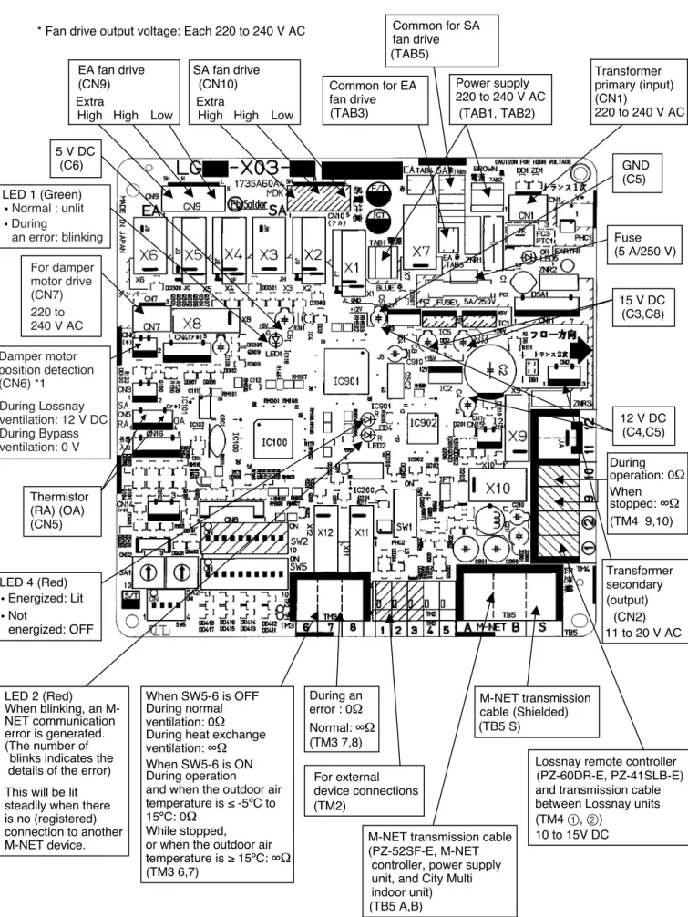
Located on the Lossnay circuit board are the terminals for the external output of the Lossnay operating state and the input terminals for the external switching of the fan speed and the Lossnay ventilation mode. Operation Monitor” and “Bypass Operation Monitor” are shared with “Operation Monitor with Delay Function 1” and “Operation Monitor with Delay Function 2” respectively.
When the aforementioned switches (SW2, and SW5) are at the factory setting, type LGH-15 to 100 will all be at the OFF setting, and type LGH-150 and 200 will all be set to OFF except for SW5-10
In systems with multiple Lossnay units, ensure that one unit is set to "Main" and all the others are set to. When locked with an external device, be sure to connect the external device to the Lossnay it is set to. Functions can be switched from the PZ-60DR-E even after the function selector is set on the Lossnay PCB.
Settings of the PZ-60DR-E override the settings of the function selector switch of the Lossnay board.). When two remote controllers are used, “24HR VENTILATION”, “LOSSNAY FUNCTION” and “INTERLOCK SETTING” can only be set on the “Main” remote controller. The "Main" and "Sub" remote controllers are automatically determined by communication when the main unit is turned on.
The page where "24HR VENTILATION", "LOSSNAY FUNCTION" and "INTERLOCK SETTING" are displayed is the "Main" remote control. For information on operating the PZ-60DR-E, refer to the Lossnay remote control PZ-60DR-E installation manual and the operating instructions.
Change
When using two remote controls, the 24-hour ventilation setting is not allowed by the "Sub" remote control. Even during high/low ventilator speed switching input (Refer to pages 33 and 34), 24-hour ventilation (extremely low ventilator speed operation) will be prioritized. When two remote controls are used, the following settings are only allowed for the "Main" remote control.
Installation
2Operation moni-
2Automatic venti-
6 : Pressing the “fan speed adjustment” button during the power supply/exhaust operation at the start of the operation will result in a change of the fan speed. 8 : The setting of the operation monitor output selection will be disabled when the setting is to Operation monitor output with delay function 1 with the TM4 9, 0) output setting switch (SW2-8) on the Lossnay circuit board, or when the setting is to Operation monitor output with delay function 2 with the TM3 6, 7 output setting switch (SW5-6). Switching the ventilation mode will not be possible during night purging (bypass ventilation is fixed).
Hold the A button and simultaneously press the F button for 2 seconds, or L button) (Hold the A button and at the same time. This mode displays the total working hours of Lossnay, checks the Lossnay address and displays the error history .If the remote control is entered into Maintenance Mode during timer operation, the timer operation will be cancelled.
When using two remote controls, if one remote control is set to remote control maintenance mode, Button response can sometimes be slow due to communication processing; this is not an error. Alternately displays at 0.5 second intervals the fault number, generated attribute and address as the most recent fault history stored with the remote control.
This shows the error number and attribute when the address is not set (i.e. address 00).
16Maintenance
17Dot display
Troubleshooting
Is the address setting on the Lossnay circuit board (SA1, SA2) set to the correct number. When using only one Lossnay, the Main/Sub switch (SW1) on the Lossnay circuit board is set to "Sub". Check the external signal type and setting of the pulse input switch (SW2-2) on the Lossnay circuit board.
Check the setting of the lock mode setting switch (SW5-7, SW5-8) on the Lossnay circuit. Check the setting of the address setting switches (SA1, SA2) on the Lossnay circuit. The length of the transmission cable installation is longer than specified (longer than a maximum of 200 m from the power supply unit, longer than 500 m between the ends).
The length of the transmission cable wiring is longer than specified (longer than maximum 200 m from the power supply unit, longer than 500 m between ends). The length of the transmission cable wiring is longer than specified (longer than maximum extension 200 m, longer than 500 m between ends). When using PZ-60DR-E, “POWER VENT START” is set to “on” with the function selection of the remote control.
When using the PZ-60DR-E, “RECOVERY SETTING” is set to “on” or “AUTo” with the function selection of the remote controller. When the PZ-60DR-E is not used, the function selector switch (SW2-6 or SW5-4) on the Lossnay PCB is set to ON. When using PZ-60DR-E, “RECOVERY SETTING” is set to “oFF” with the function selection of the remote controller.
The length of the transmission cables is longer than specified (longer than the maximum extension of 200 m, longer than 500 m between ends). When not using the PZ-60DR-E, the function selection switches (SW2-6 or SW5-4) on the Lossnay circuit board are set to ON. Check the operation monitor output setting with the PZ-60DR-E function selector or the function selector switch (SW5-2) on the Lossnay circuit board.
Disassembly and assembly
4 Slide the connector covers (with the connector) towards the side of the Lossnay core and then remove it from the unit. Remove the side engine EA in the same way.
Parts catalog
Please note the following when using the parts catalog
When ordering parts, always indicate the part number, part name, and the number of parts required
Parts are not always available, and it may take time for you to receive them
There may be specification improvements
Parts marked are critical for safety. To maintain safety and performance, always replace these parts with the parts prescribed
The numbers that are circled in the exploded view are the same as the reference number for the part being indicated
LGH-15RX5-E
LGH-25RX5-E
LGH-35RX5-E
LGH-50RX5-E
LGH-65RX5-E
LGH-80RX5-E
LGH-100RX5-E
The capacitors (1: No. 72) were changed to the new capacitors (2: No. 78) during production, so there are two types of capacitors in the market. Check the production number (year and month of manufacture) shown on the nameplate and select the applicable capacitors.
LGH-150RX5-E
LGH-200RX5-E