TECHNICAL CHANGES
EHSC-VM2B EHSC-VM6B EHSC-YM9B EHSC-TM9B EHSC-VM6EB EHSC-YM9EB ERSC-VM2B. EHSC-VM2B.UK EHSC-VM6B.UK EHSC-YM9B.UK EHSC-TM9B.UK EHSC-VM6EB.UK EHSC-YM9EB.UK ERSC-VM2B.UK.
SAFETY PRECAUTION
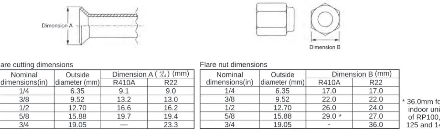
1 Flaring must be carried out in such a way that the flare meets the size for R410A. Use the flare nut supplied with the indoor and outdoor units. If existing piping has been used for a gas or oil heat pump system, make sure to clean the piping. Although the refrigerant piping for R410A is the same as for R22, exclusive tools are required to avoid mixing with different types of refrigerant.
Therefore, to increase the air tightness and strength, the flare cut dimension of copper pipe for R410A has been specified separately from the dimensions for other refrigerants as shown below. Dimension B of flare nut for R410A is also partially changed to increase strength as shown below. Tools exclusive to R410A Tools exclusive to R410A Tools for HFC refrigerant Tools exclusive to R410A Tools exclusive to R410A Ester oil, ether oil and alkylbenzene oil (minimum quantity).
Exclusive tool for R410A. A tool exclusive to R410A. Tools for other refrigerants can be used if equipped with a backflow check adapter. Tools for other coolants can be used by adjusting the blast dimension. You can use tools for other refrigerants. You can use tools for other refrigerants. Tools for other refrigerants. can be used Tools for other refrigerants can be used Tools for other refrigerants can be used. Use the new tool as a tool exclusively for R410A.) : Tools for other refrigerants can be used under certain conditions.
SPECIFICATIONS
DATA
OUTLINES AND DIMENSIONS
Handle for movingGround terminal Clamp connection Left・・・Power supply wiring Right・・Indoor/outdoor wiring Handle for movingService panel 21. Solenoid valve (four-way valve) High pressure switch Low pressure switch High pressure sensor Thermistor
WIRING DIAGRAM
Solenoid valve (4-way valve) High pressure switch Low pressure switch High pressure sensor thermistor
WIRING SPECIFICATIONS
REFRIGERANT SYSTEM DIAGRAM
If “CENTRAL CONTROL” is displayed, the collection of the coolant (pumping down) cannot be completed normally. Press the pump down SWP switch (push button type) on the control board of the outdoor unit. The compressor and ventilators (indoor and outdoor units) start working (refrigerant collection starts). LED1 and LED2 on the control board of the outdoor unit are lit.).
However, even if the unit stops and the pump down SWP switch is pushed less than 3 minutes after the compressor stops, the refrigerant collection operation cannot be performed. Because the unit automatically stops in about 3 minutes when the refrigerant collection operation is completed (LED1 off, LED2 on), be sure to close the gas ball valve quickly. If the refrigerant collection operation is completed normally (LED1 off, LED2 on), the unit will stay stopped until the power supply is turned off.
In this case, use coolant recovery equipment to collect all the coolant in the system. 7 Turn off the power supply (circuit breaker), remove the gauge manifold, then disconnect the coolant pipes.
TROUBLESHOOTING
Point the remote controller at the sensor on the indoor unit and press the HOUR button. Point the remote controller at the sensor on the indoor unit and press the ON/OFF button.
FUNCTION SETTING
5 When the settings are completed, press the button to enter the Grp. data from the remote controller to the indoor units. Setting number display section Setting number 1 = Average operating result of the indoor unit Setting number 3 = TEST built-in sensor of the remote controller. Note: When you switch to the function selection mode on the wireless remote control operation area, the unit will automatically exit the function selection mode if no input is made for 10 minutes or more.
Function selection using wireless remote control is only available for cooling system with wireless function. Aim the wireless remote control at the indoor unit's receiver and press the button. Aim the wireless remote control at the indoor unit's receiver and press the button.
Point the wireless remote control at the sensor of the indoor unit and press the button. It flashes when the remote is powering up or when there is an error. Function setting Make settings for indoor unit functions as needed via the remote control.
Remote control check When the remote control is not working properly, use the remote control control function to troubleshoot the problem. The setting of the following remote control functions can be changed using the function selection mode of the remote control. When the remote controller is connected to the device that has automatic operation mode, the following settings can be made.
Details of operating data including each thermistor temperature and error history can be confirmed with the remote control.
MONITORING THE OPERATION DATA BY THE REMOTE CONTROLLER
Note: Certain indoor/outdoor combinations do not have a request code feature; therefore, request codes are not displayed. Outdoor unit - Liquid pipe temperature 2 Outdoor unit - Two-phase pipe temperature (TH6) Outdoor unit - Outdoor air temperature (TH7) Outdoor unit - Heat sink temperature (TH8) Discharge superheat (SHd). Indoor unit - Liquid pipe temperature (Unit No. 1) Indoor unit - Liquid pipe temperature (Unit No. 2) Indoor unit - Liquid pipe temperature (Unit No. 3) Indoor unit - Liquid pipe temperature (Unit No. 4) Indoor unit - Condition/Eva.
Indoor unit - Control mode Outdoor unit - Control mode Compressor - Frequency control mode Outdoor unit - Fan control mode Actuator output state Error content (U9). Outdoor unit-Capacity setting display Outdoor unit-Setting information Outdoor unit-SW1 setting information Outdoor unit-SW2 setting information Outdoor unit-SW4 setting information Outdoor unit-SW5 setting information Outdoor unit-SW6 setting information Outdoor unit-SW7 setting information Outdoor unit-SW8 setting information Outdoor unit-SW9 setting information Outdoor unit-SW10 setting information. Display of replacement/washing operation execution Outdoor unit-Microprocessor version information Outdoor unit-Microprocessor version information (sub no.).
Outdoor unit - Liquid line 1 temperature (TH3) at the time of the error Outdoor unit - Liquid line 2 temperature at the time of the error Outdoor unit - 2-phase line temperature (TH6) at the time of the error Outdoor unit - Outdoor air temperature (TH7) at the time of the error Outdoor unit - Heatsink temperature (TH8) at time of error Discharge superheat (SHd) at time of error. Thermo ON time until operation stops due to an error Indoor - Liquid Line Temperature at the time of the error Indoor - Cond./Eva. temperature at time of error Inside at time of error. Indoor unit-Model setting information Indoor unit-Capacity setting information Indoor unit-SW3 information. side of the indoor control board) setting Indoor unit-SW5 information.
EASY MAINTENANCE FUNCTION
4 Coolant/heat exchanger temperature COOL : HEAT : 5 Coolant/discharge temperature COOL : HEAT : 6 Air/outdoor air temperature COOL : HEAT : (air/discharge temperature) COOL :HEAT. Air/intake air temperature COOL : HEAT : (air/discharge temperature) COOL :HEAT : 8. Coolant/heat exchanger temperature COOL : HEAT. 7 Room intake air temperature) – (8 Room heat exchanger temperature) Is "D000" continuously displayed on the remote control.
In heating mode, the operating state may change due to the formation of frost on the external heat exchanger. 7 Internal temperature of intake air)— (8Internal temperature of heat exchanger) (8 Internal temperature of heat exchanger) — (7 Internal temperature of intake air) .. temperature of heat exchanger) [5 Outlet temperature] – [8 Internal temperature of heat exchanger). If the unit has been moved or if the refrigerant has been additionally charged, the initial learning data must be reset and the learning performed again.
Connect the short circuit pin for the emergency operation connector (CN31) on the external controller board to the ON side. This air conditioner (outdoor unit) can detect refrigerant leakage that may occur during a long period of use. To enable leak detection, the following settings are required to let the unit memorize the initial state (initial amount of refrigerant).
1.How to select Coolant Leakage Detection mode Detection is possible regardless of unit operation (ON or OFF). The initial leak detection tutorial is always done once after a fresh install or data reset. When the unit is removed and reinstalled or the chiller is recharged, the "Initial Learning" must be performed again following the procedure below.
1. Under the following condition, the operation cannot be stabilized and the judgment of the verification operation may not be accurate.
DISASSEMBLY PROCEDURE
See picture 5) Loosen the 3 clamps and the cable strap for the lead wires in the electrical parts box. Removal of High Pressure Switch (63H), Low Pressure Switch (63L) and Pressure Sensor (63HS) (1) Remove the service panel. Refer to procedure 8) (5) Pull the high and low pressure switch jumper wire. 7) Remove the welded part of the high pressure switch, the low pressure switch and the pressure sensor (63HS).
See Figure 6) Unscrew the 3 fasteners and cable tie for the lead wires in the electrical box. See Procedure 9) (5) Pull out the lead wire of the high and low pressure switch. 7) Remove the welded part of the high pressure switch, low pressure switch and pressure sensor (63HS). See Figure 12-1) (5) Disconnect the lead wires from the reactor and remove them. 4 screws, screw 0, securing the reactor to remove the reactor.
