SAFETY PRECAUTION
For repairs to the cooling systems, (1-3) through (1-7) must be completed before work is performed on the systems. Where electrical components are changed, they must be fit for purpose and to the correct specification. This will be reported to the owner of the equipment so that all parties are notified.
Before recharging the system, it must be pressure tested with the appropriate purge gas. The equipment must be marked as having been taken out of service and emptied of refrigerant. The recovered refrigerant must be returned to the refrigerant supplier in the correct recovery container and the relevant waste transfer slip arranged.
The evacuation process must be carried out before returning the compressor to the suppliers. To speed up this process, only electric heating of the compressor body will be used.

SPECIFICATIONS
DATA
OUTLINES AND DIMENSIONS
WIRING DIAGRAM
Never connect the power cable or the indoor-outdoor connection cable, otherwise it may result in smoke, fire or communication failure. Reactor Resistor Noise Board Circuit Current Capacitor Control Panel Circuit Circuit Board Fuse
WIRING SPECIFICATIONS
If the optional indoor power supply terminal kit is used, change the indoor unit electric box wiring by referring to the figure in the right and the DIP switch settings of the outdoor unit control board. Label affixed near each wiring diagram for the indoor and outdoor units Outdoor unit DIP switch settings (when only separate indoor/outdoor unit power supply is used). Power supply cables and indoor unit/outdoor unit connection cables must not be lighter than polychloroprene sheathed flexible cable.
Set the lowest number in the group for the outdoor unit whose refrigerant address is "00" as its M-NET address. In group B, the M-NET address of the outdoor unit whose refrigerant address is "00" is not set to the minimum in the group. In A control models, M-NET address and refrigerant address should be set only for the outdoor unit.
To build a central control system, the M-NET address setting should only be done on the outdoor unit. In the system where multiple outdoor units are connected, the terminal (A, B, S) on the M-NET terminal block must be connected separately to the other outdoor units.
REFRIGERANT SYSTEM DIAGRAM
If “CENTRAL CONTROL” is displayed, the collection of the coolant (pumping down) cannot be completed normally. Press the pump down SWP switch (push button type) on the control board of the outdoor unit. However, even if the unit is stopped and the pump-down SWP switch is pressed less than 3 minutes after the compressor has stopped, the refrigerant collection cannot be performed.
Because the unit stops automatically in about 3 minutes when the refrigerant collection operation is completed (LED1 off, LED2 on), be sure to close the gas stop valve quickly. If the refrigerant collection operation is completed normally (LED1 off, LED2 on), the unit will stay stopped until the power supply is turned off. In this case, use refrigerant recovery equipment to collect all the refrigerant in the system.
7 Turn off the power supply (circuit breaker), remove the manifold to the pressure gauge, and then disconnect the refrigerant pipes. If the refrigerant pipes are disconnected while the compressor is running and the stop valve is open, the pressure in the refrigerant circuit may become extremely high if air is sucked in, causing pipes to burst, personal injury, etc.
TROUBLESHOOTING
Point the remote control at the sensor on the indoor unit and press the ON/OFF button.
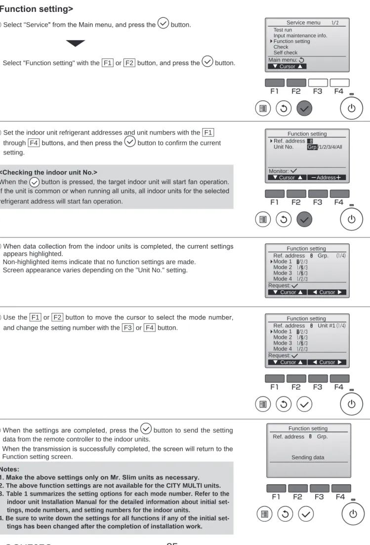
FUNCTION SETTING
2 Use the F1 to F4 buttons to set the refrigerant addresses and unit numbers of the indoor unit, then press the button to confirm the current setting. 5 When the settings are complete, press the button to send the setting data from the remote controller to the indoor units. Press the ON/OFF button (D in the figure on the previous page) so that it flashes in the unit number display area.
Press the [ CLOCK] buttons ( and ) (C in the picture on the previous page) to select the unit number of the indoor unit for which you want to perform function selection. Press the button (MODE E in the picture on the previous page) to confirm the refrigerant address and unit number. When the refrigerant address and unit number are confirmed by pressing the MODE button (E in the picture on the previous page), the corresponding indoor unit fan operation will start.
Press the [ TEMP] buttons ( and ) (F in the picture on the previous page) to select the desired setting number. Setting number display section Setting number 1 = Indoor unit operating average Setting number 3 = Remote controller built-in sensor TEST. Note: When switching to function selection mode on the wireless remote controller's operation area, the unit automatically exits function selection mode if nothing is input for 10 minutes or longer.
Function selection using wireless remote control is only available for refrigerant system with wireless function. Point the wireless remote control towards the receiver of the indoor unit and press the button. Point the wireless remote control towards the receiver of the indoor unit and press the button.
If a unit number is entered that cannot be recognized by the unit, 3 beeps of 0.4 seconds will be heard. Point the wireless remote control at the sensor of the indoor unit and press the button. Note: Do not use the wireless remote control for 30 seconds after completing the function setting.
MONITORING THE OPERATION DATA BY THE REMOTE CONTROLLER
It is not possible to switch to [Maintenance Monitor] during data request in maintenance mode (i.e. while flashing) as no buttons are operational. The requested data will be displayed in the same way as in maintenance mode at C.). Certain indoor/outdoor combinations do not have the request code feature; therefore no request codes are displayed.
Outdoor unit - Liquid pipe temperature Outdoor unit - 2-phase pipe temperature (TH6) Outdoor unit - Ambient temperature (TH7) Outdoor unit - Coolant temperature (TH8) Discharge superheat (SHd). Indoor unit- Intake air temperature (unit no. 1) Indoor unit- Intake air temperature (unit no. 2) Indoor unit- Intake air temperature (unit no. 3) Indoor unit- Temperature of intake air (unit no. 4. Indoor unit - Liquid pipe temperature (unit no. 1) Indoor unit - liquid pipe temperature (unit no. 2) Indoor unit - liquid pipe temperature ( unit No. 3) Indoor Unit - Liquid Pipe Temp (Unit No. 4) Indoor Unit-Cond ./Eva.
Indoor Unit Control Status Outdoor Unit Control Status Compressor Frequency Control Status Outdoor Unit Fan Control Status Actuator Output Status Error Content (U9). Outdoor unit capacity setting display Outdoor unit setting information Outdoor unit-SW1 setting information Outdoor unit-SW2 setting information Outdoor unit-SW4 setting information Outdoor unit-SW5 setting information Outdoor unit-SW6 setting information Outdoor unit-SW7 setting information Outdoor unit-SW8 setting information Outdoor unit-SW9 setting information Outdoor unit-SW10 setting information. Display of the execution of the replacement/wash operation Information about the version of the outdoor unit and the microprocessor Version information about the outdoor unit and the microprocessor (sub no.).
Compressor-operating current during failure Compressor-total operating time during failure Compressor-number of operating hours during failure Discharge temperature during failure. Outdoor unit-2-phase pipe temperature (TH6) at the time of fault Outdoor unit-ambient temperature (TH7) at the time of fault Outdoor unit-heat sink temperature (TH8) at the time of fault Discharge overheating (SHd) at the time of fault. Internal - Fluid pipe temperature at time of fault Internal - Cond/Eva. pipe temperature at time of fault Internal at time of fault.
Indoor unit-Capacity setting information Indoor unit information-SW3. indoor control panel setup) Indoor unit information-SW5. Maintenance data such as indoor/outdoor unit heat exchanger temperature and compressor operating current can be displayed with Trouble-free Maintenance.
EASY MAINTENANCE FUNCTION
Depending on the combination with the outdoor unit, this may not be supported by some models. If stable operation is not required or if you want to check the data with the air conditioner turned off, proceed to step (4). 4 Refrigerant/heat exchanger temperature COOL °C HEAT °C 5 Refrigerant/discharge temperature COOL °C HEAT °C 6 Air/outdoor air temperature COOL °C HEAT °C (Air/discharge temperature) COOL °C HEAT °C.
Air/intake air temperature COOL °C HEAT °C (Air/discharge temperature) COOL °C HEAT °C 8. Coolant/heat exchanger temperature COOL °C HEAT °C. 7 Indoor intake air temperature) – (8 Indoor heat exchanger temperature) "D000" is displayed stably on the remote control. In heating mode, the operating mode may vary due to frost formation on the outdoor heat exchanger.
7 Indoor inlet air temperature)— (8 Indoor heat exchanger temperature) (8 Indoor heat exchanger temperature) — (7 Indoor inlet air temperature).
DISASSEMBLY PROCEDURE
Remove the service panel and top panel. 1) Remove 3 service panel fixing screws (5 × 12) and slide the hook to the right to remove the service panel. Disassembly of the electrical parts box (VKA type) (1) Disconnect all the connectors on the controller circuit board. The electrical parts box is fixed with 2 hooks on the left and 1 hook on the right.
