Water plate heat exchanger Plate heat exchanger Plate heat exchanger Fan Fan (drive) x Nr. Screw fan x 2 Screw fan x 2 Screw fan x 2. Defrost method Reverse cycle Reverse cycle Reverse cycle.
Specifications
Mr.SLIM+
Zubadan
Capacity
1) Packaged-type units Power inverter
2) Split-type units Power inverter
Parallel connection ACH70-40 x 2 Parallel connection The table shows performance data obtained when a plate heat exchanger is connected. Recommended plate heat exchanger ACH70-40 x 2 Parallel connection The table shows performance data obtained when a plate heat exchanger is connected.
PUHZ-W50VHA(-BS)
Maximum outlet water temperature (1) Packaged-type units
Power inverter
2) Split-type units
PUHZ-SW100/120VHA PUHZ-SW100/120YHA
PUHZ-RP200/250YKA
PUHZ-SHW80/112VHA PUHZ-SHW112/140YHA
Available range (Water flow rate, return water temp.) (1) Packaged-type units
Heating
PUHZ-W85VHA2(-BS)
PUHZ-SW40/50VHA(-BS)
PUHZ-SW100/120VHA(-BS) PUHZ-SW100/120YHA(-BS)
When a recommended plate heat exchanger is installed
Outlines and dimensions
Packaged-type units
Unit : mm
Split-type units
100mm or more as long as no obstruction is placed on the back and left and right sides of the unit. Please secure the unit firmly with 4 foundation bolts (M10). Bolts, washers and nuts must be purchased locally).
FOUNDATION BOLTS
PIPING-WIRING DIRECTION
Rear air intake Side air intake Refrigerant GAS piping connection (FLARE)W15.88(5/8 inch) Refrigerant LIQUID piping connection (FLARE)W 9.52(3/8 inch) *1 Indication of STOP VALVE connection location. Hole for power supply wiring (ø27 Knockout) Hole for right piping (Knockout) Hole for cable tray on the right (Knockout) Hole for power supply wiring (ø40 Knockout).
PUHZ-SHW80/112VHA
Wiring diagrams
Packaged-type units
PUHZ-HW112/140YHA2(-BS)
Split-type units
Solenoid valve (Four-way valve) High pressure switch High pressure sensor thermistor
PUHZ-SW100/120VHA(-BS)
PUHZ-SW100/120YHA(-BS)
NET ADAPTER
Solenoid valve (four way valve) High pressure switch Low pressure switch High pressure sensor Thermistor
PUHZ-SHW112/140YHA
Solenoid valve (Four-way valve) High pressure switch 63L Low pressure switch 63HS High pressure sensor.
Refrigerant system diagrams
Refer to the following table to find out the meanings of the symbols in the refrigerant circuit diagram
Sensor Pressure sensor (63HS) For calculation of the condensing temperature from high pressure
PUHZ-SHW·HA)
PUHZ-SHW·HA/KA)
Packaged-type units
Split-type units
Unit : mm (inch)
Refrigerant flow in ATA Cooling Refrigerant flow in ATA Heating Refrigerant flow in HR Cooling Refrigerant flow in ATW Heating LEV-C.
Performance data
Definition of terms
NOTES
PUHZ-SW 40VHA
PUHZ-SW 50VHA
PUHZ-SW 75VHA
PUHZ-SW 100V/YHA
PUHZ-SW 120V/YHA
PUHZ-SHW 80VHA
PUHZ-SHW 112V/YHA
PUHZ-SHW 40YHA
PUHZ-SHW 230YKA
Cooling performance data <Note> These data are measured based on EN14511-2011
Heating performance data (1)Packaged-type units
PUHZ-HW140V/YHA2(-BS)
PUHZ-SW120V/YHA(-BS)
PUHZ-SHW112V/YHA
PUHZ-W50VHA(BS)
Part load chart PUHZ-W50VHA(-BS)
PUHZ-W85VHA2(BS)
PUHZ-SW100V/YHA(-BS)
PUHZ-SW100V/YHA(BS)
PUHZ-SW120V/YHA(BS)
PUHZ-SHW112V/YHA(BS)
Best COP
These data are measured based on EN14511-2011
Max COP of each model at each condition are shown
Noise criterion curves
Packaged-type units
UNIT
GROUND
Sound data is taken when the system is running stably
Relatively large noise could be heard transiently in the case 4-way valve, or LEV operates
- Split-type units
Earthquake-proof strength analysis
4.Total number of screws on one side that are more strongly pulled when the unit is inverted Nt= 2. 3.Stress that is simultaneously affected by shearing and tensile forces. 4. The total number of screws on one side that need to be tightened when the unit is inverted.
7 Earthquake-proof strength analysis <Anchor bolt> Outdoor unit
Error code table
Display Contents to be inspected (During operation) U Abnormal high pressure (63H operated)
Display Contents to be inspected (When power is turned on)
Installation location
- Choosing the outdoor unit installation location
- Outline dimensions (Outdoor unit) (Fig. 1-1)
- Windy location installation
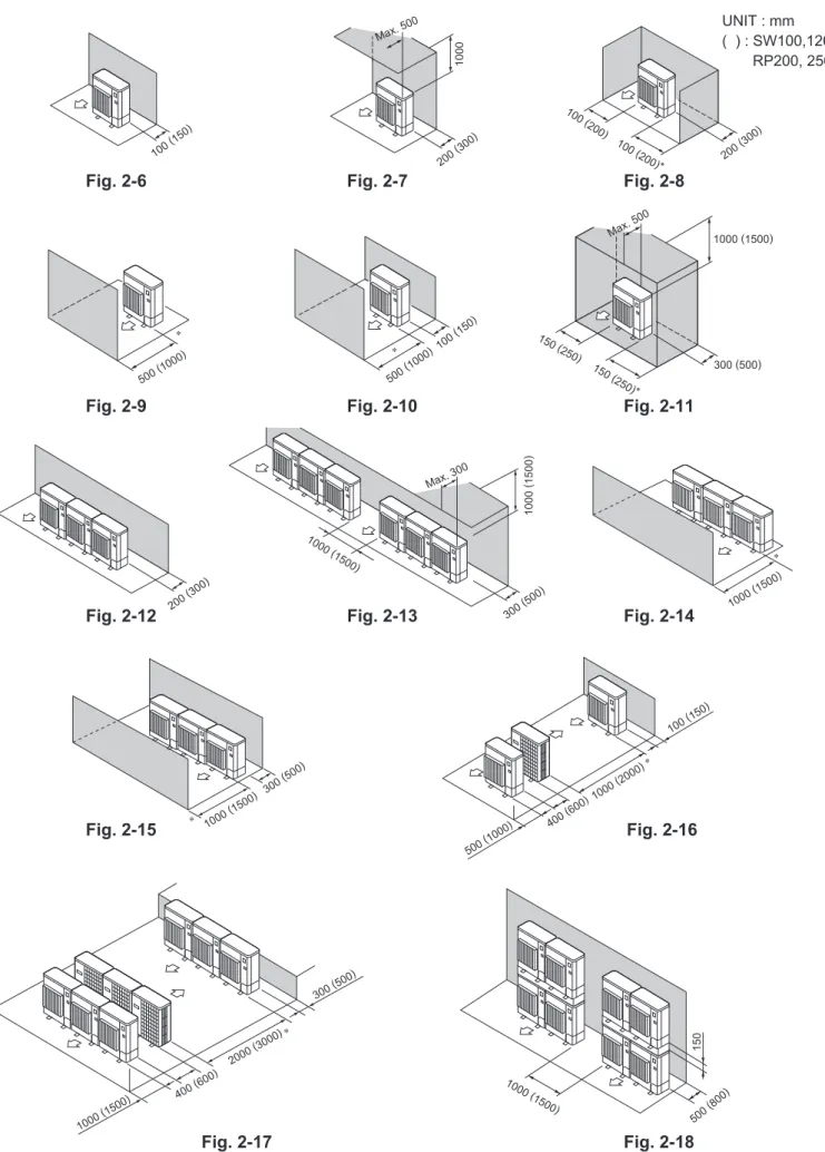
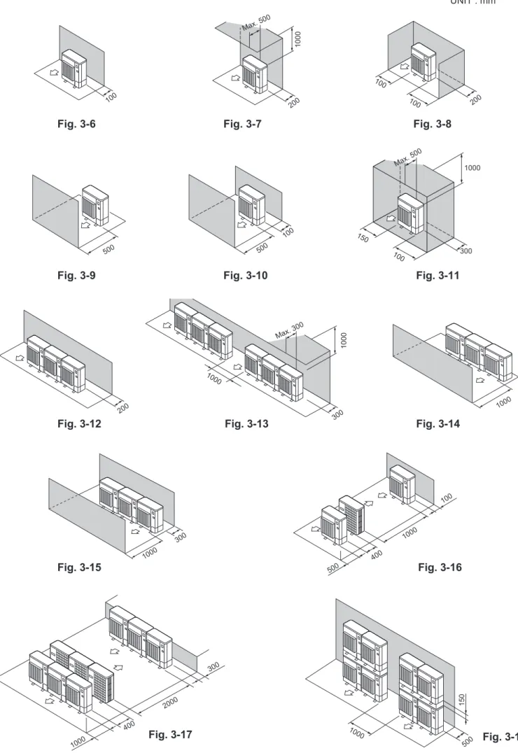
- NECESSARY SPACE TO INSTALL
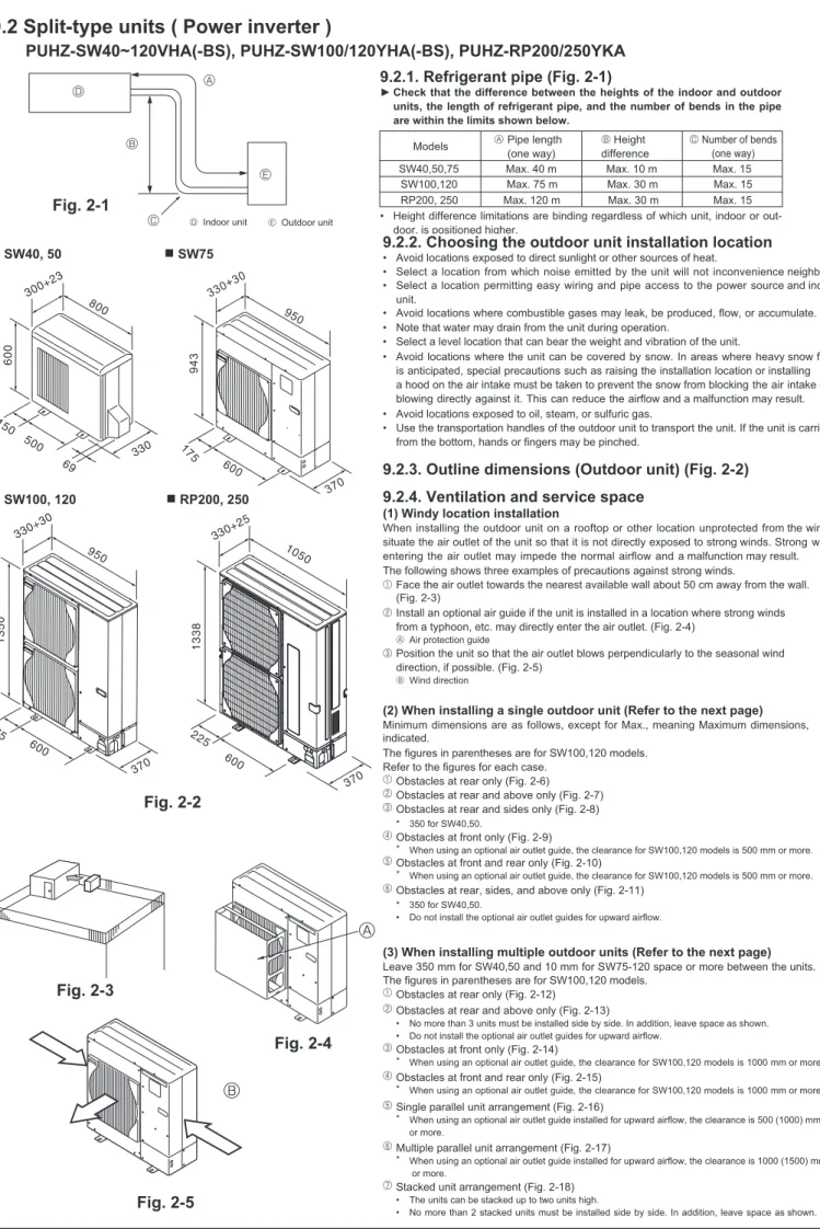
- Refrigerant pipe (Fig. 2-1)
- Split-type units ( Power inverter )
- Ventilation and service space
- Choosing the outdoor unit installation location
- Outline dimensions (Outdoor unit) (Fig. 2-2)
- Refrigerant pipe (Fig. 3-1)
- Ventilation and service space
- Choosing the outdoor unit installation location
- Outline dimensions (Outdoor unit) (Fig. 3-2)
- Refrigerant pipe (Fig. 4-1)
- Ventilation and service space
- Choosing the outdoor unit installation location
- Outline dimensions (Outdoor unit) (Fig. 4-2)
- Split-type units ( ZUBADAN )
When using an optional air outlet guide installed for upward airflow, the distance is mm or more. When using the optional air outlet guides installed for upward airflow, the distance is 000 mm or more. When using the optional air outlet guides installed for upward airflow, the distance is 500 mm or more.
MEMO
Cylinder unit / Hydrobox
Contents
Cooling mode is available only for ERSC-VM2B model (hydrobox)
- Combination table
- Cylinder unit
- Hydrobox
- Cylinder unit
2 If the water flow rate exceeds the maximum, the flow rate will be greater than 0.5 m/s, which may damage the pipes. Material - Prepainted metal Prepainted metal Prepainted metal Prepainted metal Prepainted metal. Primary circuit water - Domestic hot water - Battery in tank Battery in tank Battery in tank Battery in tank Battery in tank.
Technical Drawings
Hydrobox
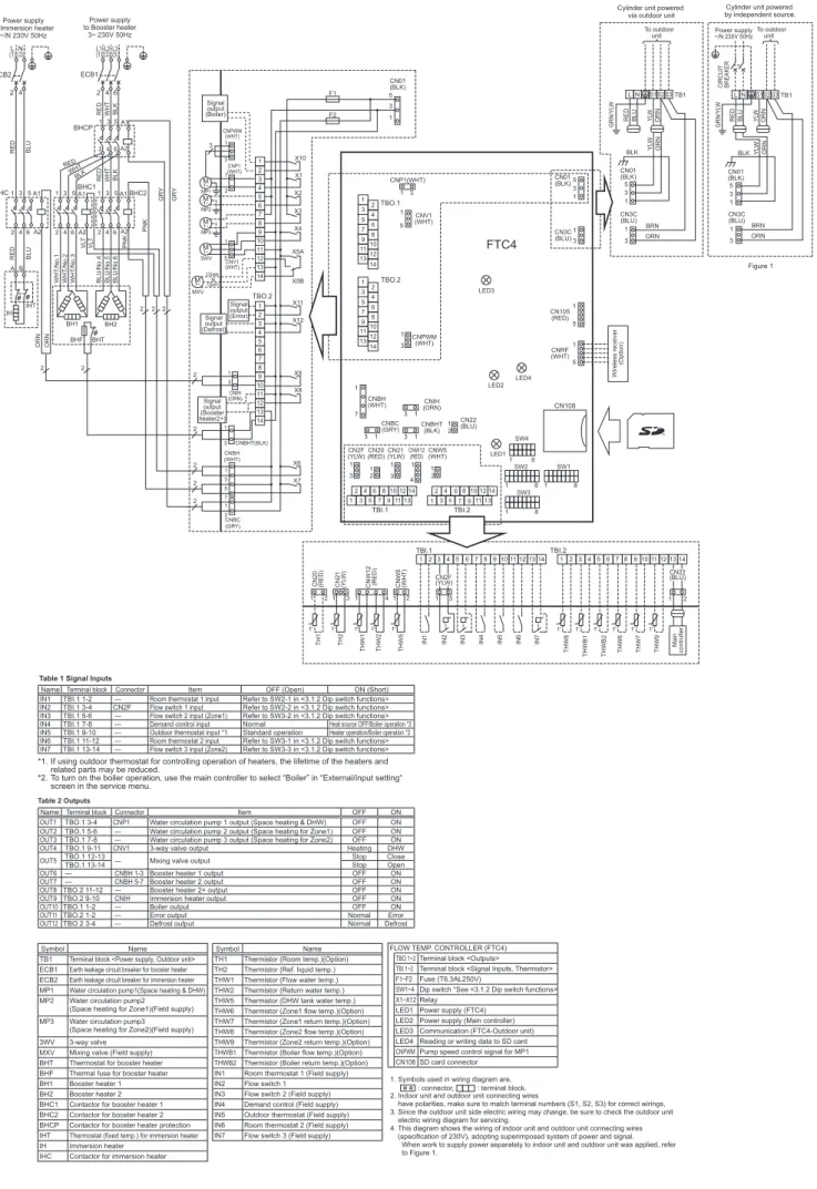
For inputs and , route high-voltage wires including power cable, indoor-outdoor cable, and outdoor output wires.
System configuration
Important Parts of the Units - Points to Note
Hydrobox
Service access diagrams
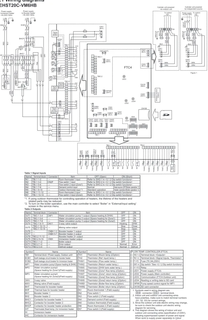
EHST20C-VM6HB
Cylinder unit .1 Wiring diagrams
EHST20C-VM6HB WIRING DIAGRAM
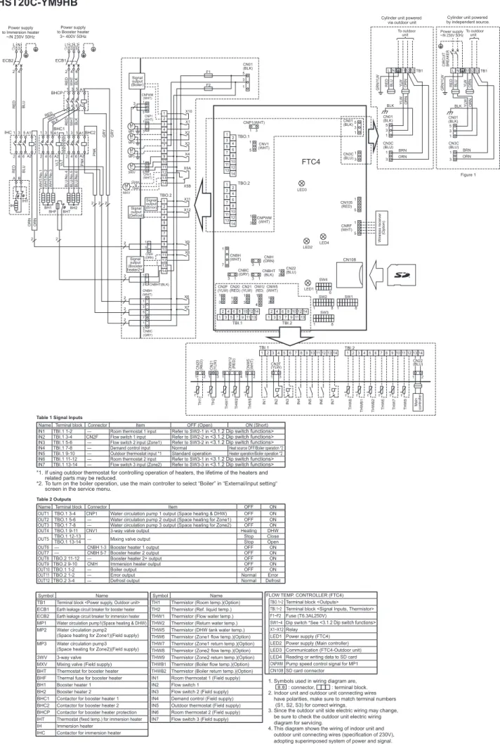
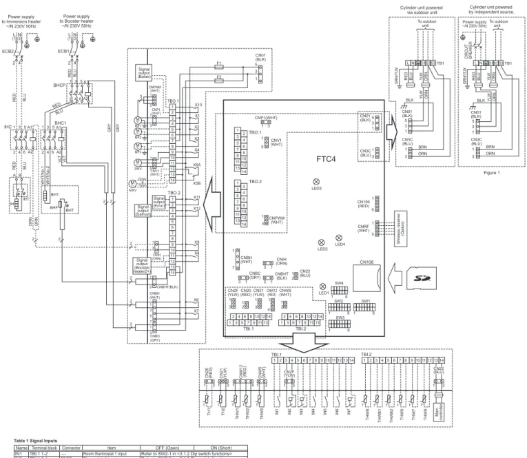
EHST20C-YM9HB
EHST20C-YM9HB WIRING DIAGRAM
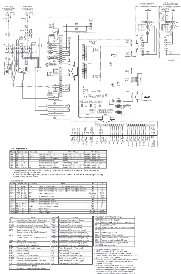
EHST20C-TM9HB
Space heating for Zone2)(Field supply) THW7 Thermistor (Zone1 return temp.)(Option) THW8 Thermistor (Zone2 supply temp.)(Option). MXV Mixing valve (field supply) THWB1 Thermistor (boiler flow temp.)(option) BHT Thermostat for booster heater THWB2 Thermistor (boiler return temp.)(option) BHF Thermal fuse for booster heater IN1 Room thermostat 1 (field supply). BHC1 Contactor for booster heater 1 IN3 Flow switch 2 (field supplied) BHCP Contactor for booster heater protection IN4 Demand control (field supplied) IHT Thermostat (fixed temp.) for electric heating coil (option) IN5 Outdoor thermostat (field supply) IH Electric heating coil (Option) IN6 Room thermostat 2 (Field supply) IHC Contactor for electric heating element (Option) IN7 Flow switch 3 (Field supply).
EHST20C-VM2B
TB1 Terminal Block
EHST20C-VM6B
EHST20C-VM6B WIRING DIAGRAM
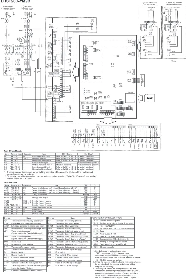
EHST20C-YM9B WIRING DIAGRAM
EHST20C-YM9B
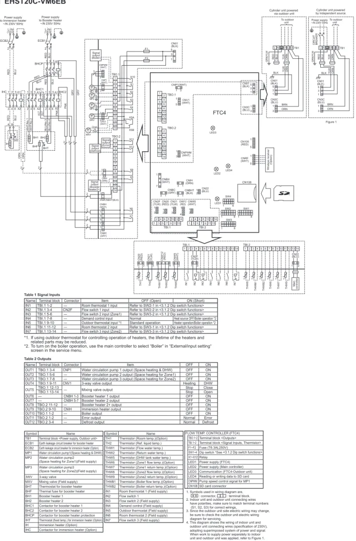
EHST20C-VM6EB
EHST20C-VM6EB WIRING DIAGRAM
EHST20C-YM9EB
EHST20C-YM9EB WIRING DIAGRAM
EHST20C-VM6SB
EHST20C-VM6SB WIRING DIAGRAM
EHPT20X-VM2HB
EHPT20X-VM2HB WIRING DIAGRAM
EHPT20X-VM6HB
EHPT20X-VM6HB WIRING DIAGRAM
EHPT20X-YM9HB
EHPT20X-YM9HB WIRING DIAGRAM
EHPT20X-TM9HB
EHPT20X-VM6B
EHPT20X-VM6B WIRING DIAGRAM
EHPT20X-YM9B
EHPT20X-YM9B WIRING DIAGRAM
Dip switch functions (Cylinder unit)
SW2-2 Flow switch input (IN2) logic change Fault detection too short Fault detection at open ON. SW3-2 Flow switch 2 input (IN3) logic change Fault detection against short Fault detection at open OFF SW3-3 Flow switch 3 input (IN7) logic change Fault detection against short Fault detection at open OFF. 3 This switch only functions when the cylinder unit is connected with a PUHZ-FRP outdoor unit.
If emergency mode is no longer required, return the switch to OFF position
SWSW4
Connecting inputs/outputs (Cylinder unit)
When connecting wires to adjacent terminals, use ring terminals and insulate the wires.
Signal inputs
Automatic switch to backup heat source operation
Thermistor inputs
Do not connect water circulation pumps to both TBO.1 3-4 and CNP1 at the same time
Connect an appropriate surge absorber to OUT10 (TBO.1 1-2) depending on the load at site
Outputs
Electrical Connection (Cylinder unit)
Install an earth longer than other cables
Please keep enough output capacity of power supply for each heater. The lack of the power supply capacity might cause chattering
Please keep enough output capacity of power supply for each heater. The lack of the power supply capacity might cause chattering
For electric cartridge (Hot water tank) For control board Outdoor unit. Power supply from the outdoor unit).
Cylinder unit powered by independent source
- Hydrobox
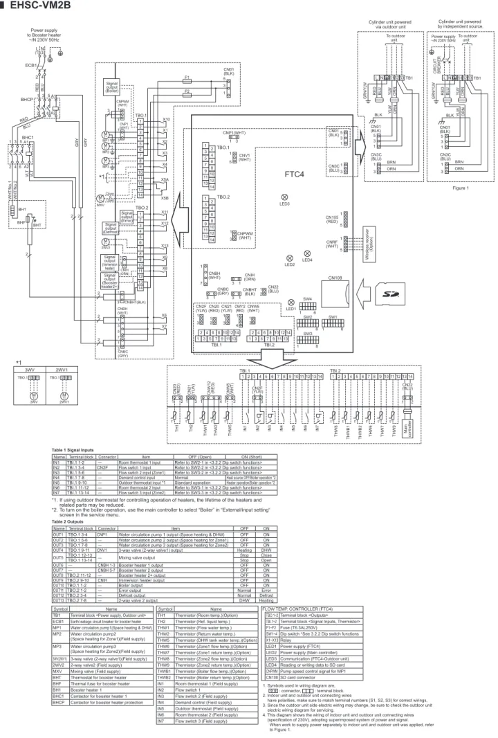
- Wiring diagrams EHSC-VM2B
Indoor unit/outdoor unit connecting cords must not be lighter than polychloroprene-sheathed flexible cord. TB1 Terminal Block
EHSC-VM6B
Space heating for Zone1) (Field delivery) THW2 Thermistor (return water temp.) THW5 Thermistor (DHW tank water temp.) (optional) MP3 Water circulation pump3. Space heating for Zone2) (Field delivery) THW6 Thermistor (flow temperature in Zone 1) (Option) THW7 Thermistor (return temperature in Zone 1) (Option) 3WV(2WV1) 3-way valve (2-way valve1) ( Field Supply) THW8 Thermistor (Zone 2 Flow Temp) (Optional) 2WV2 2-Way Valve 2 (Local Supply) THW9 Thermistor (Zone 2 Return Temp) (Optional) MXV Mixing Valve (Field Supply) THWB1 Thermistor (Temp .boiler flow) (optional) BHT thermostat for booster heater THWB2 Thermistor (boiler return temp.) (option) BHF Thermal fuse for booster heater IN1 Room thermostat 1 (local supply). BHC1 Contactor for booster heater 1 IN4 Demand control (local supply) BHC2 Contactor for booster heater 2 IN5 External thermostat (local supply) BHCP Contactor for protection of booster heater IN6 Room thermostat 2 (local supply).
EHSC-YM9B
Power supply LED1 (FTC4) LED2 Power supply (Main controller) Communication LED3 (FTC4-outdoor unit) LED4 Read or write data on SD card CNPWM Pump speed control signal for SD card connector MP1 CN108 . The indoor and outdoor unit connecting wires have polarities, make sure to match the terminal numbers (S1, S2, S3) for correct wiring. Since the side wiring of the outdoor unit may be different, be sure to check the wiring diagram of the outdoor unit for servicing.
EHSC-TM9B
EHSC-VM6EB
EHSC-YM9EB
TB1 Terminal Block
EHPX-VM2B
If you use an external thermostat to control the operation of the heaters, the life of the heaters and related parts may be reduced. To enable boiler operation, use the main controller to select “Boiler” in “External/input Setting”. BHC1 Booster heater contactor 1 IN4 Demand control (Field supply) BHCP Booster heater protection contactor IN5 External thermostat (Field supply).
EHPX-VM6B
BHC1 Contactor for booster heater 1 IN5 Outdoor thermostat (field supplied) BHC2 Contactor for booster heater 2 IN6 Room thermostat 2 (field supplied) BHCP Contactor for booster heater protection IN7 Flow switch 3 (field supplied). LED1 Power supply (FTC4) LED2 Power supply (Main controller) LED3 Communication (FTC4-Outdoor unit) LED4 Read or write data to SD card CNPWMP pump speed control signal for MP1 CN108 SD card connector.
EHPX-YM9B
BHC1 Booster Heater Contactor 1 IN3 Flow Switch 2 (Field Supply) BHCP Booster Heater Protection Contactor IN4 Demand Control (Field Supply). IN5 Outdoor thermostat (field supply) IN6 Room thermostat 2 (Field supply) IN7 Flow switch 3 (Field supply).
ERSC-VM2B
- SW4-2 is available only when SW4-1 is ON
- If emergency mode is no longer required, return the switch to OFF position
- Dip switch setting (Hydrobox)
- Connecting inputs/outputs (Hydrobox)
- When the hydrobox is powered via outdoor unit, the maximum grand total current of (a)+(b) is 3.0 A
- Connect an appropriate surge absorber to OUT10 (TBO.1 1-2) depend- ing on the load at site
- Electrical Connection(Hydrobox)
- Please keep enough output capacity of power supply for each heater. Insufficient power supply capacity might cause chattering
- Using SD memory card
- Caution on connecting DHW tank (Hydrobox)
- Wiring for 2-zone temperature control
Field supplied wiring must be entered through the inlets on the underside of the hydrobox. Check if there is a logo on the SD memory card as shown on the right. Do not power on the system at this time.) b) Insert an SD memory card. d) The LED4 light will turn on when the read and write operations are completed successfully.
Water circuit diagrams
Cylinder unit
THW2 23. THW5
Expansion vessel charge set pressure (potable side) 3.5 bar Expansion valve set pressure (potable side) 6.0 bar Immersion heater specification (potable side).
UK Packaged model system
To enable drainage of the cylinder unit, a shut-off valve should be placed on both the inlet and outlet pipes. A backflow preventer must be installed on the cold water supply pipes (IEC 6770) .. When using components made of different metals or connecting pipes made of different metals, the joints must be insulated to prevent any corrosive reaction that could damage the piping system.) . To enable drainage of the hydrobox, a shut-off valve must be placed on both the inlet and outlet pipes.
1-zone temperature control
2-zone temperature control
Local system
1-zone temperature control with boiler
2-zone temperature control with boiler
Water pipe work
Hot Water Pipework
Cold Water Pipework
Hydraulic filter work (ONLY EHPT series)
Water Quality and System Preparation
General
Anti-Freeze
New Installation (primary water circuit)
Minimum amount of water required in the space heating circuit
Existing Installation (primary water circuit)
Sizing Expansion Vessels
Filling the System (Primary Circuit)
Pipework Connections
Insulation of Pipework
Water circulation pump characteristics
Expansion vessel sizing
Performance curve external pressure
To install the EHPX series, set the pump speed with the pressure drop between the cylinder unit and the outdoor unit taken into account in the outdoor static pressure. To install the EHPT20 series, set its pump speed with the pressure drop between the cylinder unit and the outdoor unit considered in the outdoor static pressure. A safety valve must be installed between the reducing valve and the cylinder unit (see Figures 3.6, 3.7 and 3.9).
EHPT20X-VM2HB (for UK)
Install a pressure relief valve (.0MPa (0 bar)) on the local pipe connected to the cold water inlet. Note: It is essential that no check valve or isolation valve is fitted between the cylinder unit connection and the 10 bar pressure relief valve accessory (safety issue). The pressure relief valve accessory pack can be found inside the cylinder unit, glued to the base.
Safety Device Connections <Cylinder unit>
Safety Device Discharge Arrangements for UK (G3)
The single common drain must be at least one pipe size larger than the largest individual drain (D2) to be connected. Worked example: The example below is for a G½ temperature relief valve with a discharge pipe (D2) with 4 no. From Table 4.4.: Maximum resistance allowed for a straight length of 22 mm copper discharge pipe (D2) from a G½ temperature relief valve is: 9.0 m subtract the resistance for 4 No.
Piping diagram for 2-zone temperature control
Safety Device Connections
Performance curves
Combination performance
Combination performance ( Split type )
Combination performance ( Package type )
Heat time data (DHW mode)
System Set Up
Main Controller
Heat source setting Standard (Heat pump & electric heater)/Heater (Electric heater only)/Boiler/Hybrid (heat pump . & heater/boiler). Heat source Heat pump capacity Boiler efficiency Booster heater capacity Booster heater 2 capacity Floor drying function ON/OFF.
Setting the Main Controller
Initial Settings
Main Settings Menu
Domestic Hot Water (DHW)/Legionella Prevention
Legionella Prevention Mode settings (LP mode)
Heating/Cooling
Schedule timer
Holiday mode
Use the F2/F3 buttons to move to the point where you do not want the selected mode to be active, press CONFIRM to start. The schedule timer for space heating/cooling and DHW is set in the same way.
Service Menu
Auxiliary settings
Manual operation
Heat source setting
Operation settings
Low Limit Stops the heat pump operation until the flow temperature falls below the target flow temperature minus the low limit value. 2 The maximum flow temperature that allows the operation of the heat pump is equal to the maximum temperature set in the flow temperature. 1 - −10 ºC −5 Decrement Interval Sets the period for which the same target flow temperature is maintained.
Password protection
In the service menu, use the F and F2 buttons to highlight the external input settings, then press CONFIRM. Note: Selecting "OFF" while the signal is sent to IN4 will force all heat source operations and "Boiler" selection to stop. Note: Selecting “Heater”, while the signal is sent to IN5, performs operation only with electric heater and selecting “Boiler”.
Manual reset
SD card
Troubleshooting
Basic Troubleshooting for Cylinder Unit
Cylinder unit