This manual introduces you to the installation, use and maintenance procedure of the one-way air ceiling. In general, the ducts to be installed in the ceiling are not part of the Tecnair LV supply. The characteristic curve and dimensions of the absolute filter are shown in the figure below.
TRANSPORT AND CEILING ACCEPTANCE ON SITE
ASSEMBLING THE MAIN STRUCTURE OF THE AIR CEILING
Take the four identical assembled parts of the external profile vertical posts (P03) and place them on the four sides, as shown in the figure. Take an external plug-in profile (P02) and use the TEROSTAT attachment system on both side edges of each profile, as shown in the figure. Take a medium profile (A06) and use the TEROSTAT attachment system on both side edges of each profile, as shown in the figure.
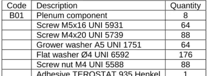
ASSEMBLING THE PLENUM
Once the first component is fixed, it is possible to move on to the adjacent one, which will be fixed on the structure as previously described. Repeat this operation for each of the plenum components, that is, anchor one of the plenum components to the structure and then anchor it to the adjacent one. The total plenum on the structure is then obtained as shown in the figure below.
ANCHORING THE CENTRAL PLAQUE
- ANCHORING IN THE STANDARD SOLUTION
- ANCHORING WITH RE-INFORCEMENT SYSTEM (ACCESSORY)
- MOUNTING THE SUPPORT FOR THE CENTRAL SUSTAIN
The standard version of the ceiling provides a central space that allows the anchoring of the real ceiling to support the OP Lamp. This is anchored before mounting the plenum and the filter ceiling. Once the plate is attached to the plate, screw the rounded rod M20 with the appropriate nuts (M20 UNI 5588) and washers (A20 UNI 1751) into one of the four holes in the plate, as shown in the figure.
If the distance between the real ceiling and the filtering ceiling is large, it is necessary to reinforce the anchoring of the central plaque (accessory). The first step is to insert the intermediate anchor plate (C02) on which the OP lamp flange tube is attached. The flange tube is part of the OP lamp supplied by the lamp manufacturer and not by Tecnair LV.
The shape and presence of the six holes for anchoring the plate are therefore brand-dependent, but largely comparable. Take the operating lamp wire tube, which is supplied by the lamp manufacturer, and attach it to the six bars of the intermediate anchorage system. The installation and mounting of the central plate is done once the central support plate (C03) is attached and used with the four spacer tubes (C04), as shown in the figure below.
Place the central support plate (C03), with the central hole going through the threaded tube of the operating lamp and the four side holes through the threaded rods.
LIFTING THE STRUCTURE
As an example, take four cables, tie them to two joint covers leaning against the supporting structure, and lift the plenum with pulleys, as shown in the figure. During the lifting of the structure, be extremely careful, as the eight terminal rods of the central support plate must be inserted into the eight holes of the central support, as shown in the figure.
ANCHORING THE STRUCTURE TO THE SLAB
In some situations, pre-drilled holes in which the small blocks must be fixed to the actual ceiling may not be available. If the drilling is done incorrectly, for example drilling through a reinforcing steel bar, it will be impossible to fix the anchor on the slab. The figure below shows how to fix it to the plate on the outer perimeter of the ceiling when the small blocks cannot be placed in some of the holes provided.
This system is more flexible, as it enables horizontal movement along the profile guides and rotational movement around the axis, i.e. it enables the ceiling to be anchored to a comfortable point. When all lateral points of the plenum are fixed, it is possible to move on to the central anchoring of the plenum. The nuts must be screwed onto the threaded rod so that the upper surface of the intermediate profiles is completely leveled.
Below we show a spirit level, a useful instrument for correctly leveling the entire construction. Start tightening the nuts relative to the profile until the profile itself is perpendicular to the flat surface, as shown in the picture. This operation must be carried out on all eight intermediate profiles, screwing them as shown in the figure, and is necessary for anchoring the structure to the real ceiling.
CLOSING THE PLENUM
Take a back closing panel (B03), place it on the external hole and insert the threaded part outwards as shown in the picture below.
ASSEMBLING THE FINAL ELEMENTS OF THE DUCTING
MOUNTING THE LAMP AND LAMP HOLDERS
Secure the brackets to the bulbs with 16 4.2x13 self-tapping screws, as shown in the figure. Once the bulbs are secured in the bracket, take this new part and insert it into the bulb holder. The choice of position is dictated only by the intensity of illumination required in the aseptic core.
Repeat the same operation on all eight sides of the structure until complete assembly of the lamp for illuminating the aseptic core is achieved.
MOUNTING THE FILTERING SYSTEM
- ASSEMBLING THE FILTER SUPPORT STRUCTURE
- POSITIONING AND ANCHORING THE ABSOLUTE FILTERS
- CLOSING THE SIDE LENGTH AND THE GASKETS OF THE FILTERS
- MOUNTING THE FLOW EQUALISER LAMINATION TISSUES
Repeat the same operation for each of the three holes on the intermediate profiles, for a total of 24 threaded rods as shown in the figure. Due to the fundamental importance of the absolute filters for the correct installation of the system, it is necessary to always check that the filters are kept in their housing and that they do not have any kind of damage. The filters are attached to the structure with their small plates and support blocks already placed on the external profiles and on the profiles of the central crown.
PLEASE NOTE: Be careful with the threaded rods that define the position of the filter. When the filter is raised, rotate the two tools to block the filter as shown in the figure. Clamp the small plate to the support block so that the small plate locks onto the filter and the profile of the central crown.
Place the sealing rods on one of the radial supports of the structure and insert three M4 threaded rods into the three holes of the rod. Once the C bars are in place, assembly of the filter system is completed with laminated flow equalizer wipes. Take the tissue, place it on one of the eight ceiling pieces using the eight C rods as shown in the picture.
Repeat the same operation for each of the eight wipes until you reach the filter system as shown in the image below.
MOUNTING THE MASK
Repeat the same operation with the other central mask until the central support is fixed as shown in the figure. Take two screws (M5x16 UNI 5931) and fasten them along the length of the structure, as shown in the figure. Take two screws (M5x20 UNI 5931) and fix the longitudinal masks on the central support as shown in the figure.
Take three screws (M5x16 UNI 5931) and attach them to the perimeter mask as shown in the pictures below. Attach all the other masks, alternating one for the length and one for the perimeter, until the surface is completely covered, as shown in the picture. Take the central block (A22), place it under the central mask and fix it with two dedicated screws (M4x20 UNI 6109) as shown in the picture.
ASSEMBLING THE FALSECEILING STEEL STRIPS
The figure below shows the counter ceiling plate after it has been mounted. Repeat the same operation for each side of the structure, as shown in the image.
MOUNTING THE POST BASE CLOSURE
Once this operation is done, the post-base closure viewed from below will look as seen below. Repeat this operation for all eight vertical posts, until the structure shown below is achieved.
MOUNTING THE STRATIFIED GLASS PANELS
After the metal disc is inserted, fasten the glass panel to the structure with four nuts (M6 UNI 5588) and four washers (Ø6 UNI 6592) as shown in the picture.
MOUNTING THE POST STEEL STRIP
Repeat the same operation on all eight strips until the assembly of the lamination ceiling is complete as shown in the figure below. The following figure shows what the Tecnair LV lamination ceiling will look like once it is installed in the false ceiling of the room.
- MAINTENANCE OF THE LAMINATION TISSUE
- AIR FILTER MAINTENANCE
- SUBSTITUTION OF THE ANTIGLAZE LAMPS
- SUBSTITUTION OF THE AIR CONTAINMENT GLASS PANELS
The basic aseptic core lighting system consists of eight antiglare lamps. Enter the counter top in accordance with the side on which the bulb is to be changed;. The lamp assembly procedure follows the reverse operation procedure described above.
The air glass panels for air retention, necessary to inhibit the flow of air and achieve the level of sterile air required by the standards, are in laminated crystal in order to guarantee maximum safety and against breaking the crystal without restricting the view . of surgeons. If there are breaks or problems with the glass panels, it is better to change the crystal with a new one. Repeat the same operation on the other vertical pillar that limits the supporting glass panels (A29);.
Unscrew the nuts and the metal washers (A28) that anchor the glass panel to the vertical posts;. The procedure for mounting the glass panels follows the opposite steps of the operations described above.