The installer must install a 400 psig relief valve in each of the two R-407C refrigerant circuits of the Liebert XDC system. For systems requiring EU CE conformity, the pressure relief valves must be CE certified by a notified body according to the EU Pressure Equipment Directive. Allow sufficient time for the compressors and refrigerant discharge lines to cool before working in the unit enclosure.
Additionally, after the action is taken and the work is completed, the facility manager MUST be informed.
P RODUCT D ESCRIPTION
General Product Information
Product/System Description
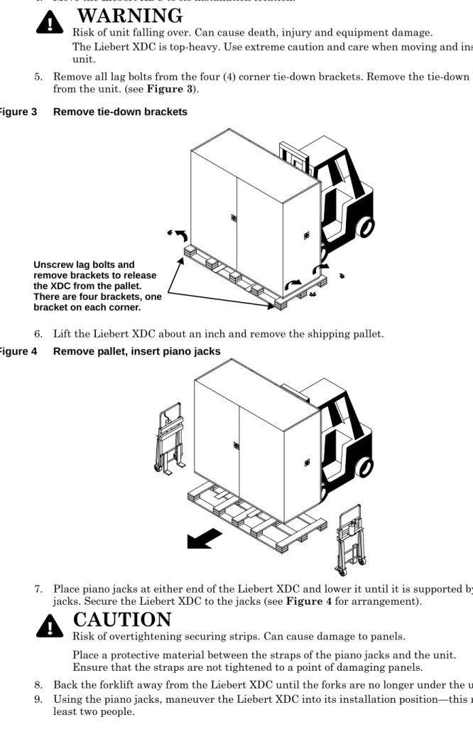
Equipment Inspection
Equipment Handling
Handling With Skid
If possible, transport the unit with a forklift; otherwise use a crane with belts or cables. If using a forklift, make sure the forks (if adjustable) are spread to the widest allowable distance that will fit under the skid. When the skidded unit is moved with a forklift, the unit must not be lifted higher than
If circumstances require the unit to be lifted higher than mm), great care should be taken and all personnel not directly involved in lifting the unit should be no closer than 20 feet (5 m) from the lifting point of the unit.
Removal of Skid
When using a crane, use spreader bars to avoid pressing on the top edges of the packaging. Place piano jacks on both ends of the Liebert XDC and lower it until it is supported by the piano jacks. Move the forklift away from the Liebert XDC until the fork is no longer under the unit.
Using the piano jacks, maneuver the Liebert XDC into its installation position—this requires at least two people.
Removing Piano Jacks
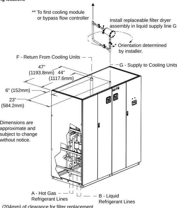
Mechanical Considerations
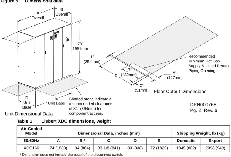
Positioning the Liebert XDC
Install the filter-drier unit between the discharge line of the Liebert XDC and the first bypass flow controller or cooling module to ensure all refrigerant flow is filtered.
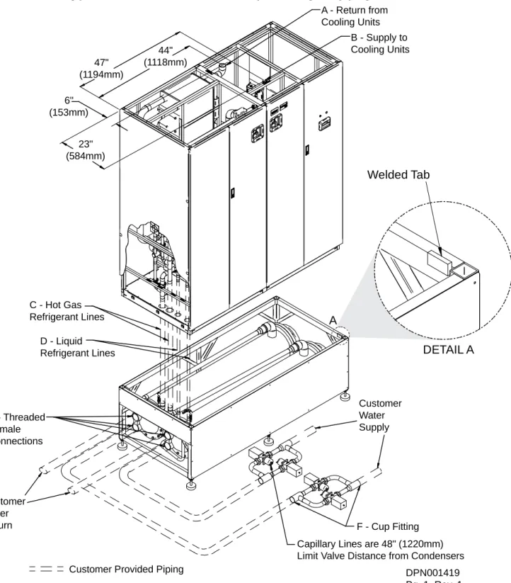
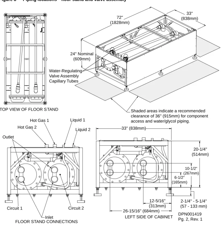
Placing the Liebert XDC on a Floor Stand
Positioning the Liebert XDC with Floor Stand
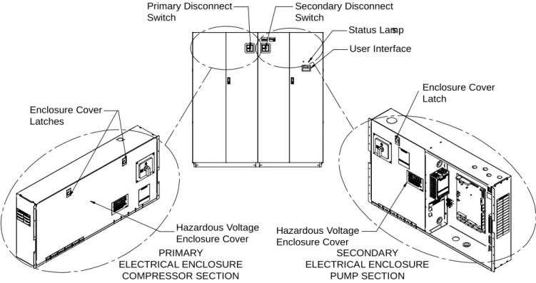
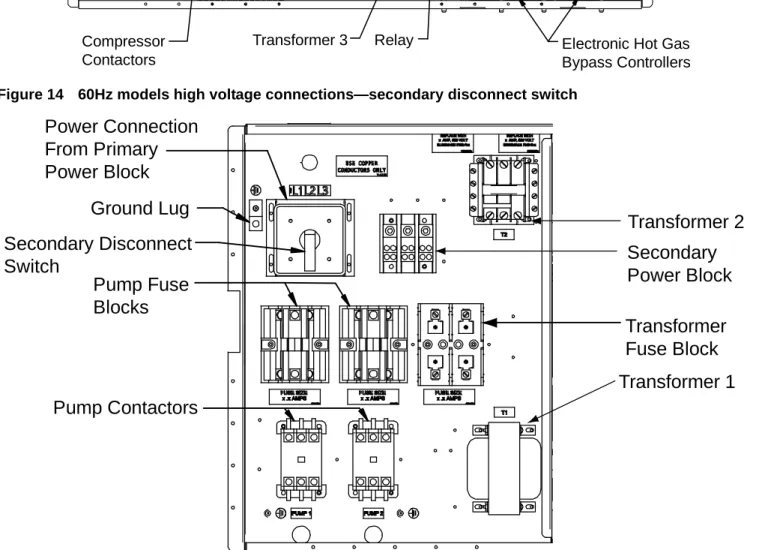
High Voltage Connections
Connecting High-Voltage Cables
Determine which cutouts in the electrical box will be used and remove them (see Figure 11). Route the hazardous voltage input electrical supply wiring through the upper right cutout on the primary electrical enclosure (see Figure 11) to the L1, L2, and L3 disconnect switches (see Figure 12). Connect the ground wire to the ground plug (see Figures 12 and 14 for 60 Hz models and Figures 13 and 15 for 50 Hz models).

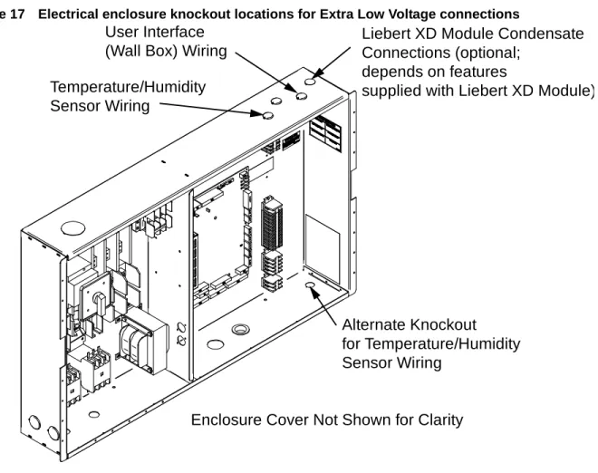
Extra Low Voltage Connections
The display panel can be mounted on the Liebert XDC's right front door if the Liebert XDC is located in the area where it is set. Place the sensor in the higher-temperature section of the cold aisle where the Liebert XD modules are located. Alternatively, it can be placed on the return air side of the primary air conditioner (eg Liebert DS™) in the room if it represents the conditions where all the Liebert XD cooling modules are located.
Connect the field wiring to the heat sink terminals on the handy box as shown in Figure 16.
P IPING AND F ILLING WITH R EFRIGERANT : R-134 A AND R-407C C IRCUITS
European Union Fluorinated Greenhouse Gas Requirements
Recommended Pipe Size
Liebert XDC Interconnection With Liebert XD Cooling Module
Piping Installation Method
Piping Installation—R-134a Pumped Circuit
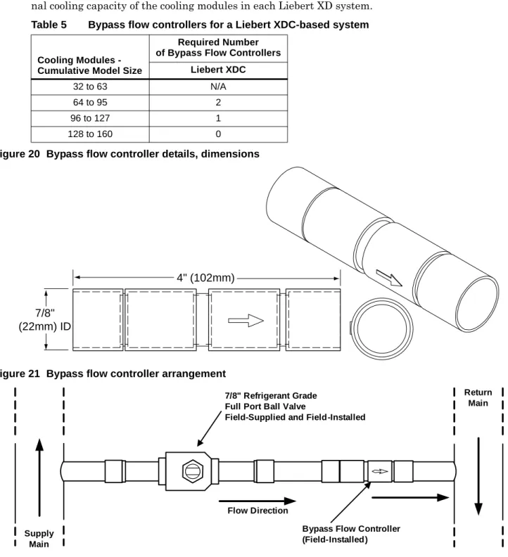
To ensure the Liebert XDC pumps operate within the optimum range, some installations require one or more bypass flow controller(s). These devices are added to the field pipes and simulate the flow of additional cooling modules. Each bypass flow regulator must be installed with a shut-off valve to allow the regulator to be disabled when cooling modules are added to a Liebert XD system.
If bypass flow controllers are required, they must be connected between the main supply and main return lines of the field piping. The connection points on the main supply and return lines should be located in a convenient and accessible location between the Liebert XDP/Liebert XDC and the first Liebert XD module in the circuit. Refer to Table 5 to determine the number of bypass flow controllers required, based on the total rated cooling capacity of the cooling modules in each Liebert XD system.
Attach a jumper hose from the Schrader valve fitting to the pump inlet to the Schrader fitting to the attached plate heat exchanger inlet (on the Liebert XD module side). After leak testing is complete, release the test pressure (per local code) and connect the vacuum pump(s) to the Schrader valves. After four hours of pulling a deep vacuum, check the vacuum level and if it has not changed, break the vacuum with dry nitrogen.
Insulate all piping between the Liebert XDC and the cooling modules to prevent condensation where piping passes through unconditioned areas. Using good pipe insulation before checking for leaks would prevent the leak from being easily detected.
Filling the Pumped Circuit—R-134a
Calculating Refrigerant Charge—Example
Using Tables 6, 7, 8 and 9, calculate the refrigerant charge in the individual parts of your Liebert XD system. Add the calculated charge amounts to determine the amount of R-134a refrigerant required for one system combining Liebert XDC with Liebert XD cooling modules (Liebert XD CoolFrame, Liebert XDH, Liebert XDO and Liebert XDV). Liebert XD Flexible Hose Liebert XDH/Liebert XDO/Liebert XDV/Liebert XDCF return diameter 5/8".
Liebert XD Flex Pipe obstoječi sistemi Liebert XDV Premer povratnega voda ft Liebert XD Flex Pipe Liebert XDH / Liebert XDO / Liebert XDV / Liebert XDCF dobava 0.2 lb. .096) 6ft Liebert XD Flex Pipe Liebert XDH/Liebert XDO/Liebert XDV/Liebert XDCF dobava 0.27lb. .126) 8ft Liebert XD Flex Pipe Liebert XDH/Liebert XDO/Liebert XDV/Liebert XDCF dobava 0.33lb. 0.15) 10 ft Liebert XD Flex Pipe Liebert XDH / Liebert XDO / Liebert XDV / Liebert XDCF dobava.
Piping for Direct Expansion (DX) Circuit—R-407C Air-Cooled Units
Install Double Discharge Risers
Air-Cooled Condenser with Liebert Lee-Temp “Flooded Condenser” Head Pressure
The Liebert Lee-Temp system consists of modulating head pressure control valves and insulated receivers with heating pads to ensure operation in ambient temperatures down to -30°F (-34.4°C). Two drain pipes and two liquid pipes must be installed on site between the indoor unit and the outdoor condenser. This will energize the solenoids and hot gas valves to open simultaneously on circuit 1 and circuit 2.
Connect the tank of dry nitrogen to the Schrader valves on the liquid lines and the hot gas lines. After completion of leak testing, release the test pressure (per local code) and connect to vacuum pump(s) at the Schrader valves on the liquid lines and on the hot gas lines. The procedures above allow the technician to use 24VAC power and controls to open liquid line solenoid valve(s) for the dehydration process.
Filling the Direct Expansion (DX) Circuit—R-407C
I NSTALLATION C HECKLIST
C HECKLIST FOR L IEBERT XDC S TARTUP
System Refrigerant Charges Over 35 lb. (15.9kg) Require Additional Oil
Liebert XDC DX R-407C Circuit Volume
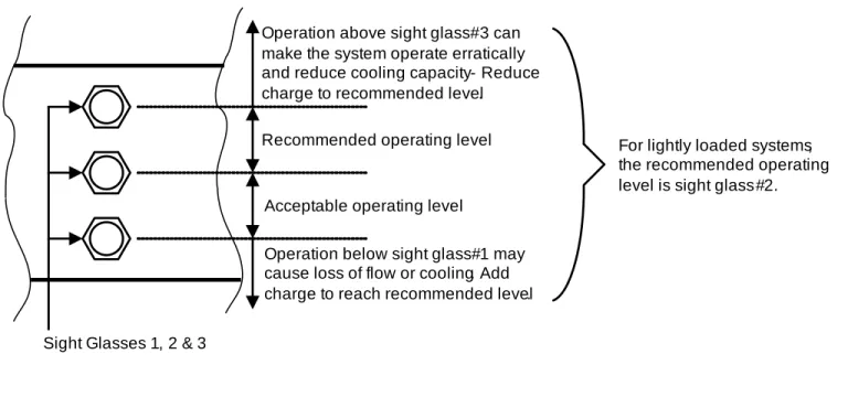
If the Liebert XDC pump cannot maintain flow and continues to cycle due to starting problems, continue to step 4 and refer to the troubleshooting section of the Liebert XDC User Manual. If steady flow is established, wait for the Liebert XDC to run for 10-15 minutes, then check that the coolant level in the receiver sight glass is between the second and third stages (see Figure 31). If there is no “Loss of flow” alarm—there is flow.
Test the pressure differential by closing the ball valve in either the suction line or the discharge line to stop the flow. This should trigger a "loss of flow on P1" alarm. This alarm confirms that the switch has been opened at low pressure (below 6 psi; 41 kPa; 0.41 bar). If there is a "Loss of Flow" alarm—This suggests that there is no flow.
Check that this is correctly annunciated by looking at the sight glass in the receiver. However, if there is flow but the differential reading is incorrect, the level will slowly drop, indicating flow, while the loss of flow alarm sounds. Physically check the pressure difference by making sure the electrical connections are properly connected.
Then check the differential pressure electrically by making sure the unit has 24VAC across it. Operation above sight glass #3 may cause the system to operate erratically and reduce cooling capacity - Reduce load to recommended level.
M ICROPROCESSOR C ONTROL
Feature Overview
Display
Feature Overview
Status Display
Main Menu
- Viewing or Changing Settings
- SETPOINTS
- STATUS
- ACTIVE ALARMS
- ALARM HISTORY
- TIME
- DATE
- SETUP OPERATION
- SETPT PASSWORD
- SETUP PASSWORD
- CALIBRATE SENSORS
- ALARM ENABLE
- ALARM TIME DELAY
- COM ALARM ENABLE
- CUSTOM ALARMS
- CUSTOM TEXT
- DIAGNOSTICS
Use the up and down arrow keys to move through the menu and view setpoints. Use the up and down arrow keys and the ENTER key to enter the three-digit password when prompted.). Use the up and down arrow keys to move through the menu and view alarm history.
Use the up or down arrow key to enter the first number of the new password. Use the up or down arrow key to enter the second number of the new password. Use the up or down arrow key to enter the third number of the new password.
Use the up and down arrow keys to navigate to the alarm you want to change. Use the up and down arrow keys and the ENTER key to enter a three-digit password.). Use the up and down arrow keys to navigate to the ALARM DELAY menu.
Use the up and down arrow keys to move through the menu and view alarm time delays. Use the up or down arrow key to change the character with the pointer below it.
A LARM D ESCRIPTIONS AND S OLUTIONS
Alarm Descriptions
SHORT CYCLE C1A – Activated when compressor 1A turns on, turns off, and turns on again, 5 times within 10 minutes or 10 times within 1 hour. SHORT CYCLE C1B – Activated when compressor 1B turns on, off and on again, 5 times within 10 minutes or 10 times within 1 hour. SHORT CYCLE C2A – Activated when compressor 2A turns on, turns off, and turns on again, 5 times within 10 minutes or 10 times within 1 hour.
SHORT CYCLE C2B – Activates when compressor 2B is cycled on, off and on again, 5 times within 10 minutes or 10 times within 1 hour. HIGH COOLANT TEMP 1 – Activates when the coolant temperature sensed by coolant temperature sensor 1 exceeds the user specified set point. COOLANT TEMP LOW 1 – Activates when the coolant temperature sensed by coolant temperature sensor 1 falls 1.5 degrees Fahrenheit below the coolant temperature setpoint.
Alarm will reset itself if the coolant temperature rises again before the control shuts down due to low coolant temperature. COOLANT SENSOR 1 FAIL – Activated when the control stops receiving a signal from the coolant temperature sensor 1. If this alarm becomes active, the control will cool down more slowly over a period of 9 minutes.
This alarm will shut down the Liebert XDC, main power (power switch) must be turned OFF and then back ON to clear this alarm. LOSS OF POWER – Enabled when the unit is powered up and operational and 24VAC power to the controller is lost to the controller.
Green and Red Lamp Indicators
Enable / Disable Alarms
Alarm Time Delays
View Active Alarms
View Alarm History
System Shutdown Causes
T ROUBLESHOOTING
Check the Liebert XD cooling modules and make sure they are turned on before starting the Liebert XDC. Install the sensor on the return air side of the primary air mover (ie Liebert Deluxe System 3).

M AINTENANCE
Fluorinated Greenhouse Gas Requirements
Air-Cooled Condenser
Water/Glycol Floor Stand Condenser
Shell and Tube Condensers
Regulating Valves
Glycol Solution Maintenance
S PECIFICATIONS