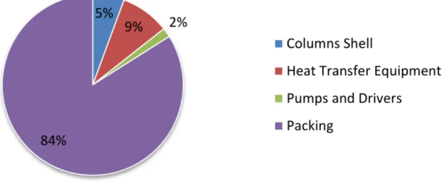
Of the total cost obtained, 69% is due to the steam required in the regeneration section. 67 Figure 7.23 – Variation of the optimal specific total cost with the MEA mass fraction imposed on CO2.
Introduction
- Motivation
- State of the Art
- Original Contributions
- Dissertation Outline
For well-known solvents such as monoethanolamine (MEA), recent developments focus on process improvement to reduce the economic penalty for capture. To this end, the gCC® PSE libraries were used to construct a MEA solvent-based capture plant model.
Background
- Carbon Capture and Storage
- Carbon Capture Technologies
- Post-Combustion Capture
- Pre-Combustion Capture
- Oxy Combustion
- Processes Based on Chemical Absorption
- Primary and secondary amine based processes
- Tertiary amine based processes
- Ammonia based processes
- Amino acid salts based processes
- Hot potassium carbonate based processes
- Processes Based on Physical Solvents
- Available technology
Post-combustion capture (PCC) is applied in power stations based on the combustion of a fossil fuel (coal, natural gas or oil), where a capture unit is used to remove the CO2 present in the flue gas. In the case of unhindered amines the global stoichiometry is 1:2 between CO2 and the amine.
![Figure 2.1 – Existing technologies for CO 2 separation and capture [16].](https://thumb-eu.123doks.com/thumbv2/123dok_br/19768852.0/28.892.156.738.163.445/figure-2-1-existing-technologies-separation-capture-16.webp)
Materials and Methods
- Chemical Absorber (A)
- Chemical Stripper (ST)
- Condenser (C)
- Flow Multiplier (FM)
- Heat Exchanger (HX)
- Heat Exchanger Process/Utility (HXU)
- Junction (M)
- Process Sink (S)
- Process Source (SR)
- Pump Simple (P)
- Stream Converter Absorber/Stripper (SC)
- Reboiler (R)
- Recycle Breaker (RB)
- Utility Sink (SU)
- Utility Source (SRU)
Heat and mass transfer in both films are modeled according to Fick's law and the gSAFT thermodynamic model (see Section 3.3) is used to predict the physical properties of each phase. The chemical stripper model is similar to the chemical absorber model except for the difference in the thermodynamic model for predicting physical properties. Isothermal and isenthalpic steady state model, used for specifying a stream flow rate (manual mode) or its inlet/outlet pressures (advanced mode).
This model is required to transition between the physics package used in the absorber and striper models due to the different operating conditions. As with the source capture model, temperature and phase must be specified, while flow rate and pressure can be displayed or calculated by the downstream unit.

Physical Properties Package – gSAFT
Models Validation
Flowsheet A – Absorber Model Validation
Therefore, Billet & Schultes correlation is a more reliable method for calculating the mass transfer coefficients in the absorber model. Through figure 4.3 it can be observed that at higher lean loads there is a reduction in the deviation achieved. This higher driving force leads to a maximization of the errors associated with the correlation used to calculate mass transfer coefficients, thus increasing the error in the predicted value of the CO2 flux across the liquid film and consequently in the calculated amount of CO2 absorbed.
According to Tobiensen et al. this can lead to an error of 2% in the calculation of the mole fraction of CO2 in the flue gases. From the temperature profiles, it is possible to observe in three sets the maximum near the top of the column (at approximately 3 m).
![Table 4.2 - Characteristic data and constants for Sulzer Mellapak 250Y TM [54, 57].](https://thumb-eu.123doks.com/thumbv2/123dok_br/19768852.0/50.892.338.556.138.275/table-characteristic-data-constants-sulzer-mellapak-250y-tm.webp)
Flowsheet B – MEA Capture Plant Model Validation
As mentioned in section 2.3, the specific heat consumption is a key indicator of the process costs and takes into account the heat consumed in the reboiler (QReb). Considering that in example 1 there is a lower lean load, according to the conclusions of the previous sections, there should be a significant overprediction in the CO2 capture rate. However, since the reboiler heat consumption is not enough for the required amount of CO2, the collection rate is reduced, leading to a minimization of the variation caused by the overestimation in the absorption section.
Since the shear load in example 2 is higher, the variation associated with the absorption in the section is reduced. In the same way, for a given capture rate the specific heat consumption tends to be overestimated.
![Table 4.5 – Pilot plant design parameters [11].](https://thumb-eu.123doks.com/thumbv2/123dok_br/19768852.0/55.892.194.705.140.209/table-4-5-pilot-plant-design-parameters-11.webp)
MEA Full Scale Capture Plant Model
Base Case
Several flow multiplier models (FM-301 to FM-310) were added to this model at the inlets and outlets of the absorber, regeneration section and boiler to simulate the existence of equipment working in parallel. For the evaluation of the necessary number of absorption and stripping trains, the technical limitations found through the internal reports of PSE have been taken into account. In addition, it should also be considered that the vapor velocity in both columns should be between 70 and 80% of the vapor flooding velocity, [54], as this velocity ratio is a product of the column design.
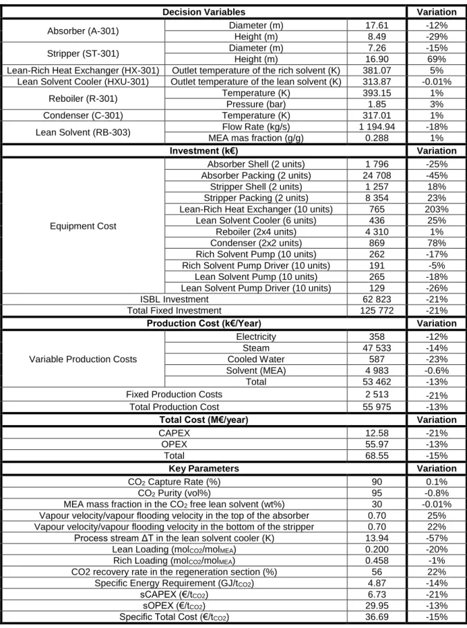
The values obtained for these variables, as well as the main simulation results obtained for the original and corrected cases are shown in Table 5.3. The flowsheet obtained after correction for the standard capture conditions was later used as a comparison with the optimization results, being defined as the base case.

Cost Estimation Model
- CAPEX Estimation
- OPEX Estimation
The table above also shows the parameters a, b and n, which are used in the cost correlations for calculating the purchased equipment cost (𝐶𝑒). For the calculation of the number of spare pumps, it was considered the existence of a spare pump for each set of pumps operating in parallel. For the variable production costs, the annual consumption of utilities (steam, cooling water and electricity) and solvent was considered.
𝑂𝑃𝐸𝑋 = 𝐶𝑚𝑎𝑖𝑛𝑡𝑒𝑛𝑎𝑛𝑐𝑒+ 𝐶𝑡𝑎𝑥𝑒𝑎𝑛𝑟 𝑐𝑒+ 𝐶𝑢𝑡𝑖𝑙𝑖𝑡𝑖𝑒𝑠+ 𝐶𝑠𝑜𝑙𝑣𝑒𝑛𝑡 (5.9) For an annualized utilization of solvent consumption, 0 was taken into account. For the estimation of the power consumption, the power required in both lean solvent and rich solvent pump drivers was considered.
![Table 5.4 – Type, construction/reference material, sizing variable and cost correlation parameters for the main capture plant equipment [58]](https://thumb-eu.123doks.com/thumbv2/123dok_br/19768852.0/62.892.110.806.207.490/construction-reference-material-variable-correlation-parameters-capture-equipment.webp)
Cost Estimation Results for the Base Case
Therefore, it was considered that the concentration of MEA in the treated flue gas is reduced to this value, and the recovered MEA is used as part of the required replenishment. As mentioned in the previous section, solvent consumption is the result of solvent loss due to decomposition and evaporation in the stripper and absorber, considering that the solvent. Without water washing, the loss of amine in the absorber represents 77% of the total loss of 12.5 kt/year.
It is also possible to see that OPEX (and total cost, considering the importance of OPEX over CAPEX) is mainly affected by the steam consumed in the regeneration reboilers, which is directly related to the heat required. Therefore, it is expected that the optimization of the flow sheet of the capture plant will rely mainly on the change of absorbers.
Optimisation Problem Formulation
Objective Function
Decision Variables
From the variables listed in the table above, the parameters referred to the make-up recirculation breaker model will define the flow rate and MEA concentration of the lean solvent. The MEA mass fraction in the lean solvent must be a decision variable to allow the lean loading to vary and keep the MEA mass fraction in the CO2-free lean solvent constant. As mentioned in the previous section, the boiler temperature is not included in this list of variables, as a value is already imposed to simplify the optimization process.
Constraints
Since the vapor velocity varies across the column, the variation of this ratio across the column height was considered for the base case (Figure 6.1). For the conditions considered, the maximum ratio is obtained in the absorber near the top of the columns (Height = 0 m), which gives a small variation. On the other hand, the maximum ratio of the stripper is verified at the base of the columns (Height = 10 m).
Taking into account the high values obtained for the optimal heights of the stripper and absorber in section 7.1.4, it was necessary to apply a minimum pressure at the top of both columns (since the working pressure is specified at the bottom ), to ensure operation at least under atmospheric conditions. As for the minimum temperature difference in the inlets and outlets of the heat exchangers, this is required to ensure the optimization convergence, as it is no longer determined by the respective costs.

Optimisation Results
Base Case Optimisation with Standard Constraints
- Specific Total Cost Minimisation
- Effect of the Initial Guesses in the Optimisation Results
- Effect of the Number of Absorption Trains
- Specific Heat Requirement Minimisation
From this figure it is also possible to deduce that the heat exchanger equipment has more relevance in the total cost, mainly due to the increase in the cost of the lean heat exchanger. Nevertheless, the total water consumption is reduced by 23%, due to the reduction verified in the lean solvent cooler. Due to the increased efficiency of the stripping column, the CO2 flow rate in the vapor leaving each re-evaporator is in each stripping train.
This leads to an increase in the importance of CAPEX in the total cost to 59%, as can be observed in Figure 7.11. These reductions are possible due to an increase in the height of the stripping columns to 337%, and a decrease in the lean solvent flow rate to 13%.
Effect of the Process Constraints
- Effect of the Capture Rate
- Effect of the CO 2 Purity
- Effect of the MEA Concentration
- Specific Total Cost Minimisation with Inequality Constraints
The effect of the degree of coverage in the specific total cost was tested for values of 70%, 80%. Nevertheless, changing the temperature of the rich solvent leads to an increase in the consumption of the rich solvent heat exchanger and the cost of the lean coolers with increasing CO2 purity. In Figure 7.23, it can be observed that the specific total cost decreases with increasing concentration of MEA in the solvent.
In fact, the increase of the MEA mass fraction in the CO2-free lean solvent to 40% allows a 4% reduction in capture costs. The reduction in flow reduces the heat transferred in the poor-rich heat exchangers.
Conclusions and Future Work
Conclusions
The effect of varying the lean load prior to the optimization procedure (by varying the lean solvent flow rate and reboiler pressure) on the optimal total specific cost was tested, with a variation of less than 1% observed. This led to a further reduction of the specific heat demand to 4.46 GJ/tCO2, but at the cost of greatly increasing the height of the columns, thus leading to an increase in the total cost (143%). This leads to a 2% increase in the optimal total cost in this capture rate range.
However, it was verified that this parameter did not have a significant impact on the specific heat consumption, affecting the reduction of the total cost. These changes are mainly due to the possibility of reducing the solvent flow rate, with the increase in concentration, accompanied by an increase in the optimal charge of the league.
Future Work
The MEA concentration was varied by changing the imposed MEA mass fraction in the CO2-free lean solvent to 20% and 40%. The variation in the specific total costs was more significant than in the previous cases (except when approaching the physical limits), showing a reduction of 5% when changing this limitation from 20% to 30%, and by 4% when changing it. from 30% to 40%. Both factors contribute to the reduction of the specific heat requirement, making the total cost reduction possible.
This resulted in the optimal capture rate of 75%, CO2 purity of 88% and MEA mass fraction in the CO2-free lean solvent of 40%, which is the variable upper limit. It should also be noted that in the cost estimation model this was considered a generic degradation rate for MEA, which may no longer be applicable.
Bibliography
The calculation of the wall thickness (t) took into account both the minimum thickness (tmin) for a given diameter (Table A1.1) and the equation specified by the ASME BPV code [58]. For the calculation of the wall thickness, the maximum pressure in the container (P) is required, obtained from the column model, its diameter (D), the maximum allowable stress (S) and the welded load efficiency (E), which is assumed to be 1. The re-evaporator area is not an output of the respective model and was therefore estimated using equation (A1.5).
In addition, the pressure at the bottom of the source column (𝑃𝐵𝑜𝑡𝑡𝑜𝑚,0) and at the top of the destination column (𝑃𝑇𝑜𝑝,1) and the gravitational acceleration (g = 9.8 m/s2) are required. MEA mass fraction in the CO2-free lean solvent (wt%) 30 Vapor velocity/vapor flux velocity in the top of the absorber 0.56 Vapor velocity/vapor flux velocity in the bottom of the stripper 0.57 Process stream ΔT in the lean solvent cooler (K ) 32,56.
![Table A1.1 – Minimum practical wall thickness [58].](https://thumb-eu.123doks.com/thumbv2/123dok_br/19768852.0/105.892.284.647.455.611/table-a1-1-minimum-practical-wall-thickness-58.webp)
![Figure 2.2 – Schematic of a coal-fired power plant with carbon capture [17].](https://thumb-eu.123doks.com/thumbv2/123dok_br/19768852.0/28.892.140.751.710.1050/figure-schematic-coal-fired-power-plant-carbon-capture.webp)
![Figure 2.3 – Schematic of an IGCC power plant with carbon capture [17].](https://thumb-eu.123doks.com/thumbv2/123dok_br/19768852.0/30.892.172.722.107.416/figure-schematic-igcc-power-plant-carbon-capture-17.webp)
![Figure 2.5 – Split-flow configuration of the Fluor’s Econamine FG Plus SM process [30]](https://thumb-eu.123doks.com/thumbv2/123dok_br/19768852.0/34.892.222.679.484.765/figure-split-flow-configuration-fluor-econamine-plus-process.webp)
![Figure 2.6 – Praxair’s Amine process flowsheet [35].](https://thumb-eu.123doks.com/thumbv2/123dok_br/19768852.0/36.892.229.666.107.418/figure-2-6-praxair-amine-process-flowsheet-35.webp)
![Table 2.4 presents processes based on ammonia solvents, which are already operating in pilot plants and ready to proceed towards commercialization [40]](https://thumb-eu.123doks.com/thumbv2/123dok_br/19768852.0/37.892.109.798.933.1150/table-presents-processes-ammonia-solvents-operating-proceed-commercialization.webp)
![Figure 2.10 – UOP Selexol TM process flowsheet for CO 2 and H 2 S co-capture [50].](https://thumb-eu.123doks.com/thumbv2/123dok_br/19768852.0/40.892.259.633.778.1043/figure-10-uop-selexol-tm-process-flowsheet-capture.webp)
![Figure 2.9 - CO 2 bulk removal capacity for different solvents [49].](https://thumb-eu.123doks.com/thumbv2/123dok_br/19768852.0/40.892.271.619.268.576/figure-2-bulk-removal-capacity-different-solvents-49.webp)
![Figure 2.11 – Lurgi Rectisol ® process flowsheet for CO 2 and H 2 S selective capture [49]](https://thumb-eu.123doks.com/thumbv2/123dok_br/19768852.0/41.892.218.673.114.409/figure-11-lurgi-rectisol-process-flowsheet-selective-capture.webp)
![Table 4.1 – Characteristics of the flue gas and lean solvent used by Tobiesen et al. [10]](https://thumb-eu.123doks.com/thumbv2/123dok_br/19768852.0/49.892.123.770.430.946/table-characteristics-flue-gas-lean-solvent-used-tobiesen.webp)
