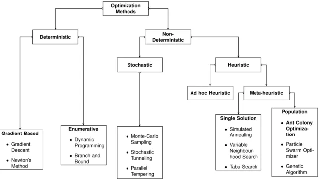
The main goal of this thesis is to find the optimal design of the wing box by performing a topology optimization using the Ant Colony Optimization (ACO) algorithm. GB Gradient-based algorithms are optimization algorithms that rely on the gradient of the objective function to find the optimal solution for the optimization process.
![Table 5.7: Aluminium 7075-T651 mechanical properties. [Metals, 2015] . . . . . . . .](https://thumb-eu.123doks.com/thumbv2/123dok_br/19768406.0/16.892.150.785.103.292/table-aluminium-7075-t651-mechanical-properties-metals-2015.webp)
High Aspect Ratio Wings
One can separate the zero-lift drag coefficient of the wing (CD0w ), from the drag coefficient due to the lift, also called induced drag coefficient (CDLw) [Roskam and Lan, 1997]. In Figure 1.3, the evolution of the wingAR of commercial aircraft over the years can be seen.

High AR Wing Drawbacks
The wing twist and loss of lift due to elevator deflection was caused by the aeroelastic properties of the aircraft and the FCS. The non-linearities of the wing and the instabilities are mainly due to the introduction of a highAR wing, which produced a large elastic structure.
Problem Statement
Airports have restrictions on the maximum wingspan allowed, which will affect the wing AR selected for the aircraft.
Thesis Outline
Stigmergy
These stimuli were seen as a way to communicate with the other termites from the colony, and were designated as stigmergy. So when we try to find the path between the nest and food source, the path chosen will most of the time be the one with the highest concentration of pheromones.
Double Bridge Experiments
One expects that half of the ants will choose one branch and the other half the other. The ants could not move from the long branch to the short branch, because they were "stuck" on the longest path.
Optimization with ACO
Travelling Salesman Problem
TSP is a problem when a seller has several cities he wants to visit to sell his products. During the round trip, the seller wants to visit each city only once and make the shortest possible trip.
Algorithm Description
This means that τij(t+n) is equal to the pheromone intensity at the edge that connects the city and the end of the cycle. The probability of choosing the given city will be a balance between the proximity and trace intensity present in the edge connecting both cities.αwill balance the relative importance of the pheromones in the node transition rule. The importance of these parameters during the optimization process will be shown in the following section (section 2.3) with a parametric study.
ACO Parametric Study
This is not true for the second point, where the colony dimension is equal to 20, although this can be explained due to the stochastic nature of the algorithm. For the β parameter, which regulates the importance given to the visibility information, one can conclude that increasing its value will increase the efficiency of the algorithm. The evolution of the tour length with the increase of the number of cycles is similar to the one seen for β, above a number of cycles the solution found will remain the same.

Mathematical Description
Rozvany, Olholf, Bendsøe et al. 1985/87) developed the first analytical solutions for the optimal perforated plates and the correct expressions for the stiffness tensor of homogenized optimal microstructures [Rozvany, 2001]. Bendsøe and Kikuchi [1988] developed the first finite element-based topology optimization for higher volume fraction, introducing the homogenization approach to solve topology optimization.
Homogenization Approach
Shape optimization, which until the introduction of the homogenization approach was closest to topology, required edge variation methods. The finite element model created at the beginning of the optimization process will be maintained throughout the optimization. Using equation (3.6), we can perform topology optimization without having to worry about the discrete formulation of the problem.
![Figure 3.2: Unit cell with rectangular centred hole [Hassani and Hinton, 1998].](https://thumb-eu.123doks.com/thumbv2/123dok_br/19768406.0/44.892.358.524.953.1119/figure-unit-cell-rectangular-centred-hole-hassani-hinton.webp)
Density Approach
The solid part of the microstructure consists of an isotropic material, which will become an orthotropic material through the rectangular hole. The density function will be a function of the first two parameters defining the rectangular hole of the cell (a, b), given by. The main disadvantage of SIMP is the dependence of the solution on the penalty parameter and not necessarily converging to the optimal solution.
![Figure 3.3: Material stiffness given by the power-law [Rozvany, 2001].](https://thumb-eu.123doks.com/thumbv2/123dok_br/19768406.0/46.892.315.571.486.737/figure-material-stiffness-given-power-law-rozvany-2001.webp)
Cantilever Beam Example
As can be seen in figure 3.5, the resulting structure of the optimization approach will depend on the value of the penalty factor. The top-down optimization process will stop when the maximum value of changes in design variables between successive iterations is lower than 0.01. It can be concluded that decreasing the penalty factor will lead to an earlier convergence of the optimization process.

ACO for a TO problem
- State of Art
- Problem Statement
- TS problem vs TO problem
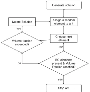
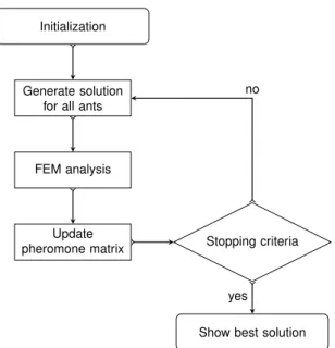
- Flowchart
- Element Transition Rule
- Pheromone Update
The elements of the domain will then be selected to maximize or minimize the chosen objective function. This can be explained by the fact that one uses the strain energy of the solution as an objective function. Consequently, it cannot be known before the solution is generated what the effect of that element's presence in the solution will be.
MATLAB R Implementation
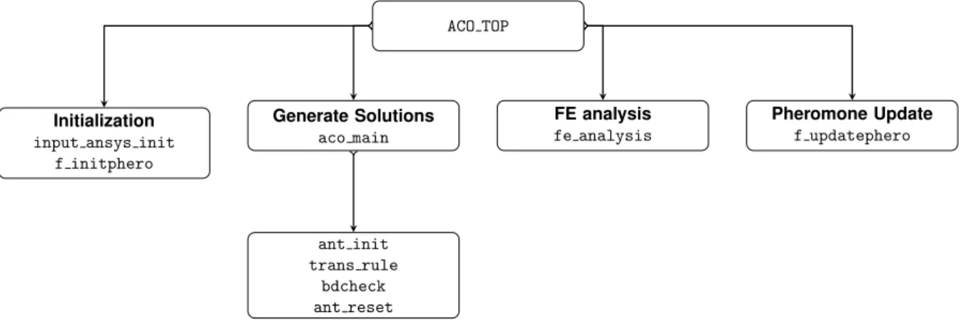
- Main function
- Pheromone Matrix Initialization
- ACO Main
- Noise Cleaning Filter
Depending on the position of the element, the number will be assigned as follows. The given numbering of the elements allows to avoid the use of the connectivity matrix, which reduces the calculation time. 2008], the pheromone matrix is initialized by assigning a constant value to each element of the design domain.

ANSYS R /MATLAB R Interface
The implementation of the filter is achieved by changing the strain energy of the element with the modified strain energy obtained using Equation 4.10 during the pheromone update. The linear propagation of strain energy across the surrounding elements will also spread the pheromone in the surrounding element, causing the ant to travel over more elements in the neighborhood of the current element compared to the case where no filter is applied.
Literature Case
Force Selection
Multiple finite analysis with the full domain was performed and the displacements obtained were recorded. From the value of the maximum displacement, one can conclude whether a linear analysis is valid or not, as it is only valid for small displacements. For a force equal to or greater than 106 [N], the maximum displacement of the full domain, compared to its Y dimension (0.4 m), has the same order of magnitude, therefore it can no longer be considered a small displacement and the performed linear analysis is no longer valid.
Literature Optimum
If a force with a large magnitude is selected, valid results may not be obtained since the FEM analysis performed is a linear analysis. The optimization process performed with the code developed for the given domain (Figure 3.4) must be performed with a force lower than or equal to 5·105[N].
Results
Parametric Study
Looking at Figure 4.12, we can conclude that with an increase in λ, the resulting structures will have better performance. By increasing λ, the algorithm had faster convergence without showing these fluctuations in value. A parametric study of the parameter ρ was performed prior to the implementation of the denoising filter.

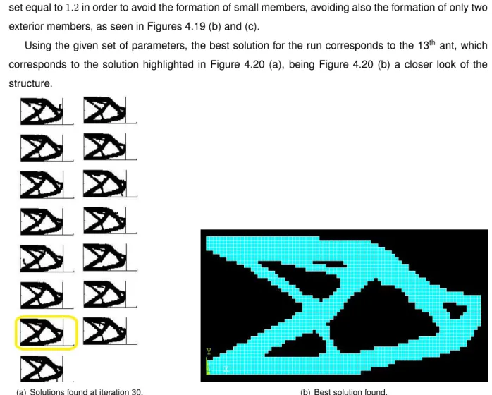
Optimum Solution
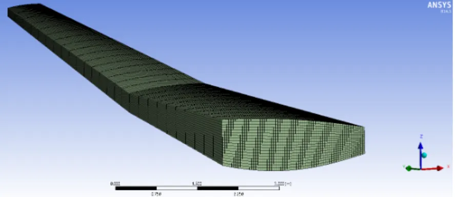
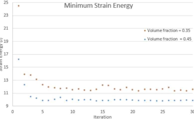
The highlighted layouts correspond to the best solutions found by the algorithm at the end of the optimization process. The results support what was mentioned before, the minimum noise energy decreases with the increase of the volume fraction. The full SolidworksR) 3D model of the NOVEMOR7thframework reference wing with an AR= 12 can be seen in Figure 5.3.
Flight Condition
CFD Analysis
- Control Volume
- Boundary Conditions
- Mesh Convergence Test
- CFD Results
So AoAtrim= 4.854o will be used to calculate velocity components to perform CFD analysis in CFXR. A symmetry boundary condition was assigned to the walls perpendicular to the X-axis intersecting the root of the wing. As you can see, the lift values obtained are lower than half of the M T OW, with a difference of 4%.

Structural Model
Wing Box Cross-section Discretization
In order to get a simpler connection between elements in the wing box cross-section, a mapped surface mesh was used in the wing box. The higher number of elements in the wing box cross-section will also mean a higher number of possible combinations of designs obtained during the optimization process. For the wing box cross section, it was defined that the number of divisions of the vertical edges would be equal to 18 and the number of divisions of the horizontal edges would be equal to 64, resulting in 1152 elements in the wing box cross section.
Mesh convergence test
The maximum wing displacement for a given aerodynamic load showed little fluctuation with increasing number of structural mesh elements. To optimize the highARwing's wing box cross-section, some modifications to the code were required. In the given model, one has a pressure distribution across the upper and lower surfaces of the wing box.
Results
- Optimization Blocks
- Boundary Conditions
- Connectivity
- Optimization Domain
During solution generation, the path of the ant (2D) will determine the shape of the cross section. Figure 6.1 shows the evolution of the cross-section of the wing box throughout the optimization process. In order to distinguish between the two elements, we will refer to the structural mesh elements as structural elements (st).
Results
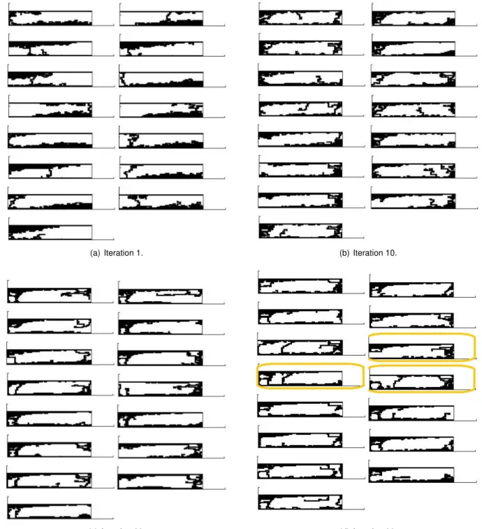
Coarse Mesh
A higher concentration of elements can be seen close to the wing root, the element concentration decreases in the span. Near the apex, few elements are present which are connected to the rest of the structure of an element. Some differences can be seen in both structures can be seen close to the root, where for the latter case the structure is not hollow.
Fine Mesh
The evolution of the minimum deformation energy during the iterations of the optimization process can be seen in Figure 7.6. The topology optimization of the wing box was first performed by only allowing changes in the cross-section, meaning that the wing box has a constant cross-section along the span. The increase in the number of design variables is also closely related to the calculation time.
Future Work
This set of parameters was used to perform the topology optimization of the high aspect ratio wing. The minimum deformation energy obtained at the end of the optimization process was equal to 14.783 Jan and 11.617 J for a volume fraction equal to 0.35 and 0.45, respectively. If a further topology optimization of the wing was performed, it would be interesting to consider the wing as solid, which would be discretized corresponding to this discretized domain to the optimization domain.
![Figure 1.3: Evolution of the wing AR of the commercial aircraft [Filippone, 2000]](https://thumb-eu.123doks.com/thumbv2/123dok_br/19768406.0/27.892.301.587.159.436/figure-evolution-wing-ar-commercial-aircraft-filippone-2000.webp)