PREPARATION FOR OPERATION
Note: when thin slippery thread (for example polyester thread) is used, feed the thread through the thread guide Bas shown in Fig.lO. B With the take-up lever in the upper position, insert each wire in the order shown in Fig.ll. B Turn the balance wheel with the hand stop when the feed dog is raised to its highest position from the surface of the needle site;.
A Turn the leveling wheel and stop when the lever rises to top dead center. A Turn the balance wheel by hand and stop when the handle of the opener is furthest from the. Push the cam follower lever so that the cam roller enters the groove of the thread trimmer cam.
Turn the balance wheel until the black mark on the arm meets the white mark on the balance wheel. Set the cam follower crank in this position with a screwdriver, temporarily preventing the cam roller from coming out of the cam groove. With the needle in the lowest position, depress the cam follower crank, turn the balance wheel until the movable knife reaches the end of its stroke.
B While maintaining the needle position, press the cam follower lock and place the cam roller into the thread cutting cam groove. C By turning the balance wheel by hand, adjust the cam of the fillet cutter so that the movable knife starts to move when the green mark dot on the balance wheel lines up with the black dot on the arm. Note: To adjust, loosen the two threaded cam clamp screws A . 24) Adjusting the needle thread tension release assembly (Fig.34).
B Hold the needle position by pressing the cam follower crank and insert the cam roller into the groove of the thread roller Thller cam. C Turn the balance wheel by hand, adjust the thread tension release cam so that the tension disc closes when the white mark on the balance wheel aligns with the black mark on the arm. Since it is very difficult to sharpen the movable knife, it must be replaced with a ne\V when it dulls (fig.36).
J Press the cam follower lock K and adjust the connecting rod L so that the cam roller can enter the groove of the thread cutting cam smoothly. A Push the cam follower lock K so that the cam roller fits into the cam groove. B Tighten the connecting rod L and adjust the gap between the cam roller and the cam groove surface as small as possible, and tighten the nuts G and H.
C Push the cam follower lever K again and check that the cam roller enters the cam groove of the thread cutter smoothly.
Latnp leads
Connection of control box
Adjustment of needle bar stop position
CAUTIONS ON USE
Lubrication (
Lubrication (
Adjustment of oiling to rotating hook
Condition of oil lubrication
Cautions on operation
C The height of the controller should be measured at the point where the needle is in the upper position. B The vertical movements of the paws become maximum when the lever is moved down and adjusted. C The vertical movements of the pawls become greatest when the crankshaft is moved up and set;
When the toothed belt (timing belt) has been removed to replace it, the relationship between the movement of the rotary hook and the movement of the lever should be. C Loosen the feeder lift drive shaft set screws A and B. D Set the needle to the lowest position. While pressing the button on the opposite side of the bed with your left hand, slowly rotate the balance wheel away from you with your right hand;
OPERATION
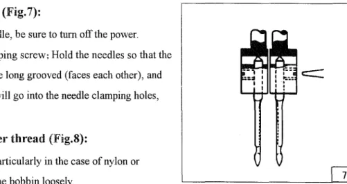
How to attach needle
How to wind the lower thread
Selection of Thread
How to route the upper thread
Adjustment of stitch length and reverse sewing
Settingbobbin
Pull wire from side A, then install the spool housing, Thread according to CD-®; Put the bc, obin casing on the rotary hook, and then replace the hook shaft; Push the spool bar and guide the bobbin thread over the bed plate.
Threading ofbobbin thread
Tension adjustment ofbobbin threads
Balance of thread tension
Needle thread tension
Adjustment of pressure of presser foot
Timing between rotating hook motion and needle motion
Adjustment of Feed dog height
Adjustment the needle stop position
Needle bar stop position (left & right)
Walking foot and presser foot vertical stroke adjustment
Relationship between hook motion and opener motion
C If the gap is too large or small, loosen the set screw B of the opener holder and adjust the position of the opener.
Relationship between needle motion and feed dog motion
The force exerted on the safety interlock is least when the mark moves from the ec<;,entric pin to the . To adjust the force, slide the timing belt, loosen the adjusting screw and turn the eccentric pin. By tightening the pin that connects the backstitch link to the backsew crank (down), you can adjust the tolerance between stitches.
Adjust the movable blade so that the slanted portion of the movable blade end protrudes 0-0.5mm from the stationary blade as shown in the figure, and tighten the bolts A and B. Turn the inner hook manually in the direction indicated by the arrow in the figure and adjust the gap between the movable blade and the inner hook stopper to about 0.5 mm (for this adjustment, screws A and B must be loosened). E The tension disc opening degree should be adjusted with the tension release roller B mounted on the convex portion of the thread release cam as shown in Fig.
G Loosen the nut D and allow the outer casing to approach to the right to increase the opening value. Note: Since excess pressure causes high torque on the thread trimming mechanism and trimming failure, adjust it so that the thread can be trimmed with minimal pressure. E Loosen the hook bracket clamp screws A and B and adjust the distance between each needle and hook.
G Contact the rocker fasteners C and D with the plug pins E and F and tighten the connecting link clamp bolt J.
Safe clutch device
Adjustnlent
Installation of movable knife
B Turn the vertical position adjustment screw B to adjust the engagement pressure, and then turn the hexagon socket screw A clockwise.
Adjustnlent ofthread trimmer cam
Adjustnlent of threads tension release assembly
Adjustnlent of scissoring pressure of movable knife and fixed knife
Sharpening of fixed knife
Adjustnlent for change ofneedle-to-needle distance
THREAD TENSION REGULATOR MECHANISM
ARM SHAFT*LOWER SHAFT MECHANISM
NEEDLE BAR & TAKE-UP LEVER MECHANISM
TOP FEED ROCK SHAFT MECHANISM
LOWER SHAFT & FEED ROCK SHAFT MECHANISM
HOOK SADDLE MECHANISM
KNIFT MECHANISM (2)
TOUCH BACK AND DETECTOR MECHANISM
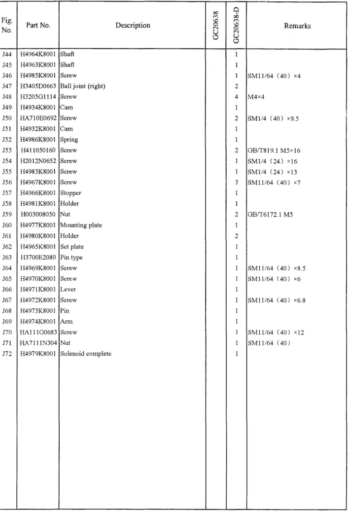
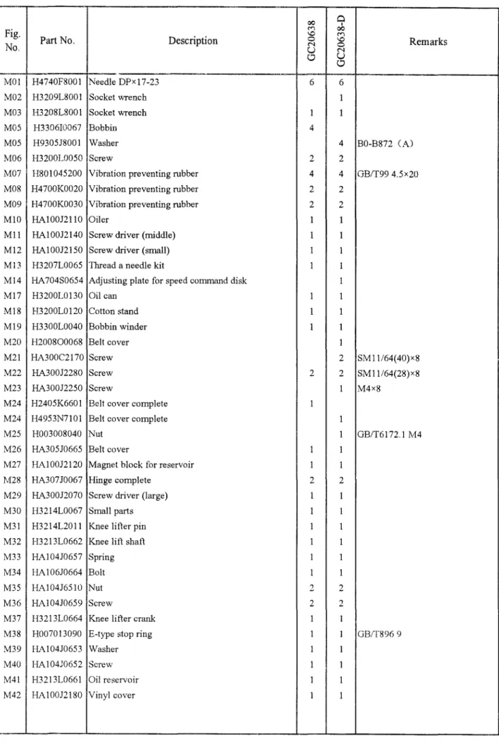
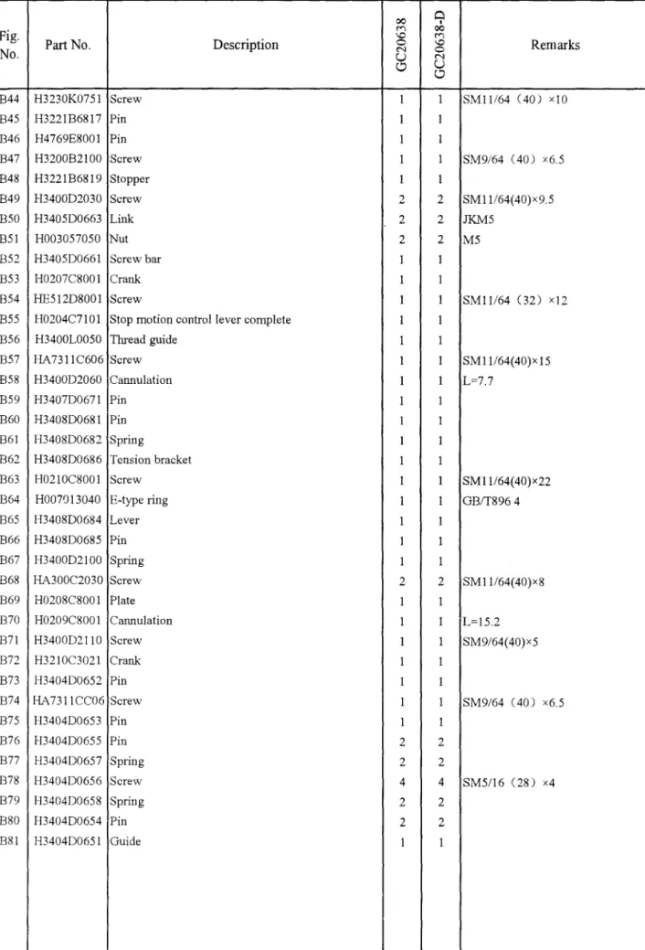
ACCESSORIES