I am grateful to my friend José Mendes, who participated in the SimUAV project with me, for always helping when I was stuck. A big collective “thank you” to the good folks at Critical Software who helped me overcome some of my limitations in computer science. Last but not least, I am grateful to my family for providing me with the conditions to develop during my life.
I'm also grateful to my friends, those who came and those who left, because I couldn't have done it without you. Flight simulators can be used to support the design of UAVs and related control stations, train operators, and perform aerospace research, offering many advantages over the use of real UAVs. This standard has proven applications in the field of space simulation and promotes simulation modularity and flexibility.
INTRODUCTION
- B ACKGROUND AND M OTIVATION
- S TATE OF THE A RT OF F LIGHT S IMULATION
- S COPE OF THE T HESIS
- T HESIS L AYOUT
In terms of system certification, the UAV flight simulator can be used to test vehicle behavior but, perhaps more importantly, to test the UAV control station. Note that a similar scenario was implemented in this thesis for the purpose of demonstrating the functionality of the UAV flight simulator. There is some evidence of European research in the area of UAV simulation, which attempts to fill the continent's underdevelopment in this area.
The aim was to support the definition of the operational requirements for the control station, as well as to test new ideas. Multiple scenarios were generated and the performance of the control station operators was evaluated, as well as their feedback. The second part of the tests focuses on scenarios involving all components of SimUAV.
![Figure 1: The UAV “closed loop dilemma” [1]](https://thumb-eu.123doks.com/thumbv2/123dok_br/19768534.0/18.892.275.572.127.388/figure-1-uav-closed-loop-dilemma-1.webp)
SOFTWARE DEVELOPMENT LIFE CYCLE
- I NTRODUCTION
- O VERVIEW
- P HASES OF S OFTWARE D EVELOPMENT
- Requirements Engineering Phase
- Design Engineering Phase
- Validation Phase
- S YNOPSIS
This requires that the high-level architecture of the software is also defined in this phase. Data: an enumeration of the internal data stored in the component that is relevant to understanding its function. Its sole purpose is to demonstrate the conformance of the software to the customer and was not performed on the current work.
An overview of the software development life cycle as implemented by Critical Software was presented, as well as the adaptation performed in the scope of this work. The need for a clear definition of software objectives was established in the description of the requirements engineering phase. The process of defining the software architecture and its implementation was presented in the section dedicated to the engineering phase of the design.
![Figure 7: Phases and milestones of the software development process [21]](https://thumb-eu.123doks.com/thumbv2/123dok_br/19768534.0/27.892.260.681.161.343/figure-7-phases-milestones-software-development-process-21.webp)
REQUIREMENTS ANALYSIS
- I NTRODUCTION
- UAV S IMULATOR R EQUIREMENTS O VERVIEW
- T ECHNOLOGY R EQUIREMENTS
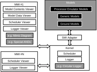
- Simulation Model Portability Standard
- SIMSAT
- H IGH -L EVEL A RCHITECTURE
- UAV F LIGHT M ODELS
- Dynamics Model
- Aerodynamics Model
- Propulsion Model
- Gravitation Model
- Terrain Model
- Atmospheric Model
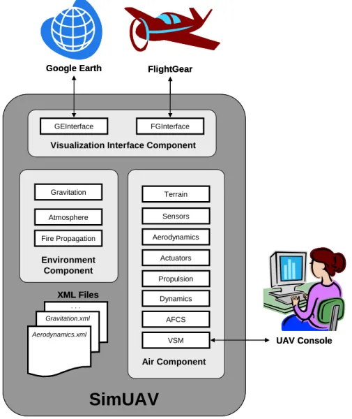
- V ISUALIZATION I NTERFACES
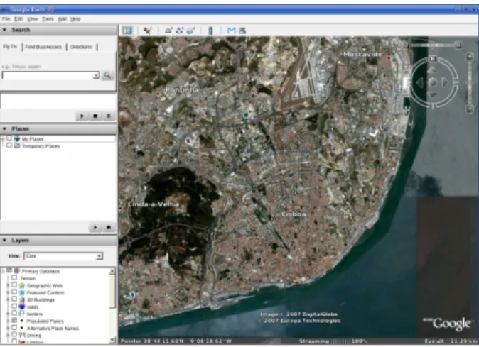
- Google Earth Interface
- FlightGear Interface
- A PPLICATION S CENARIO : F OREST F IRE M ONITORING
- Fire Propagation Model
- Fire Front Following Model
- S YNOPSIS
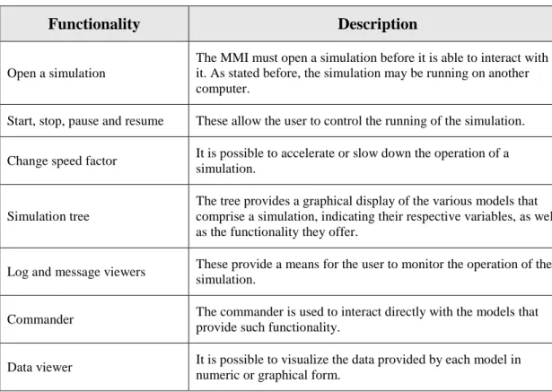
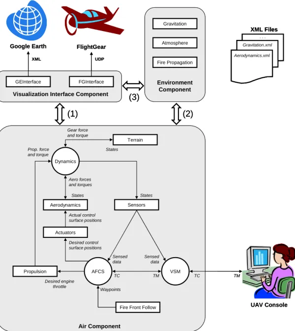
Within the framework of the same Critical Software project, but not in this thesis, a STANAG 4586 UAV console was developed to interact with the UAV flight simulator [19]. Start, Stop, Pause and Resume These allow the user to control the progress of the simulation. Log and Message Viewers These allow the user to monitor the operation of the simulation.
Terrain: This model simulates the existence of the ground by determining the force and torque generated by the chassis. Fire Front Tracking: Based on the results of the fire propagation algorithm, this model determines a flight plan for the UAV to follow the fire front. The values of the rudder, aileron and elevator positions are provided to the aerodynamics model.
The models, as a whole, should provide a baseline for simulating the flight of a UAV in the scenario of fire monitoring. This model simulates the behavior of the UAV propulsion system by providing the Dynamics model with the value of the generated power and torque. For this, the value of the height of the UAV is read from the Dynamics model.
It will also be possible for the user to manually set a location marker that defines the initial position of the UAV in the simulation in terms of latitude, longitude and altitude. The fire propagation data is only needed for the purposes of the Fire Front Following model. Based on the data generated by the Fire Propagation Model, at each moment this model will determine a waypoint to which the UAV should fly to follow the front of the fire.
A description of the requirements for SimUAV development was presented, as well as the motivation behind these requirements.
![Figure 9: SMP compliant interaction of simulation models and platforms [32]](https://thumb-eu.123doks.com/thumbv2/123dok_br/19768534.0/35.892.377.559.160.403/figure-smp-compliant-interaction-simulation-models-platforms-32.webp)
ARCHITECTURE DESIGN AND MODEL SPECIFICATION
- I NTRODUCTION
- D ETAILED A RCHITECTURE
- C OMMON M ODEL S PECIFICATION
- D ETAILED D ESIGN
- Dynamics Model
- Aerodynamics Model
- Propulsion Model
- Gravitation Model
- Terrain Model
- Atmospheric Model
- Fire Propagation Model
- Fire Front Following Model
- Google Earth Interface
- FlightGear Interface
- S YNOPSIS
The translational and rotational motion of the UAV is described by a set of four equations. Equation (4.1) shows the attitude of the ABC frame (represented by the letter 'b') relative to the ECI frame (represented by the letter 'i'). The position of the ABC frame relative to the ECI frame, in ECI frame components, piCM O/ , is given by.
The algorithm described above is used to determine the evolution of UAV states in time. The three components of aerodynamic torque (rolling moment, l, pitching moment, m, and yaw moment, n) are. In equation (4.8), VT represents the velocity modulus of the UAV relative to the air mass.
At each time step, the states of the UAV are read from the Dynamics model. The ultimate goal of this model is to determine the force and torque generated by each landing gear. At each time step, the current altitude of the UAV is read from the Dynamics model to determine the total force and torque generated by the landing gears.
At each time step, h is read from the Dynamics model and used to calculate the various parameters of the ISA model. Based on the results of the Fire Propagation algorithm, this model determines a flight plan that results in the UAV following the leading edge of the fire. The coordinates of the generated point are sent to the AFCS model, which instructs the UAV to fly to that location.
During initialization, the data necessary for the operation of this model is read from the XML, such as the range of the sensors. This file is periodically read by Google Earth, which automatically displays the UAV's position. The fourth and final supported task is visualization of the results of the fire propagation model.
VALIDATION RESULTS
- I NTRODUCTION
- U NIT AND I NTEGRATION T ESTING
- Test 1 – Latitude/Longitude Navigation and Google Earth Positioning: Defining the
- Test 2 – Translational Dynamics and Propulsion: Thrust Force
- Test 3 – Rotational Dynamics: Applied Torque
- Test 4 – Translational Dynamics and Gravitation: Orbital Mechanics
- Test 5 – Atmospheric Parameters: Values at Several Altitudes
- Test 6 – Aerodynamic Force and Wind Effects: Body Facing the Wind
- Test 7 – Terrain: Generation of Reaction Force
- Test 8 – FlightGear Interface: Visualization of UAV Position and Attitude
- Test 9 – Fire Propagation and Google Earth Fire Visualization: Observing the
- Test 10 – Google Earth Flight Plan: Defining and Loading a Flight Plan
- Test 11 – Fire Front Following: Monitoring the Evolution of a Fire
- S YSTEM T ESTING
- Test 12 – Telemetry Generation and Sending to UAV Console
- Test 13 – Following Discrete Commands
- Test 14 – Flight Plan Following and Loiter
- Test 15 – Fire Monitoring
- S YNOPSIS
This test verifies the latitude and longitude navigation features of the Dynamics model and the capacity of the Google Earth interface to position the UAV. This test verifies the generation of drive force and the response of the Dynamics model to that force. The slope of the line fits 1 (the value of the applied force) with great precision, and the graph of the position versus time can be shown as a parabola, as expected.
This test verifies the translational dynamics of the Dynamics model and the function of the Gravity model. A circular orbit around the Earth was simulated, which is possible due to the generality of the Dynamics model. The velocity of the body was expected to increase due to the pressure force until equilibrium with the aerodynamic force is reached.
Velocity doesn't start from zero like the drag force did because it is loaded when the Dynamics model is started - the model doesn't need to run once to output the velocity value.). This test checks the ability of the FlightGear interface to display the position and position of the UAV. In this test, the SimUAV was connected to a UAV console developed under the same Critical Software project [19].
Several parameters in the simulation were monitored and the simulated values reported by the SIMSAT MMI matched the values reported by the UAV console. The UAV was ordered to follow the flight plan and fly to each of the waypoints in the specified order. The UAV began autonomously following the front of the fire, starting the moment it detected its presence.
The evolution of the fire and the resulting path described by the UAV is depicted in Figure 33.

CONCLUSIONS
C ONTRIBUTIONS TO THE S TATE OF THE A RT
C ONCLUSIONS
The benefit of a clear definition of software objectives in the requirements engineering phase became apparent during the SimUAV implementation. The added value of a formal approach to software architecture specification was also observed during the implementation phase. The specification promotes modularity and flexibility by separating each model from the rest of the simulation as much as possible.
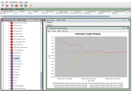
The SIMSAT platform used to run the simulation was found to be very reliable and robust, despite offering rather limited data visualization functionality. SIMSAT allowed focus on developing simulation models rather than worrying about issues such as operations planning, data transfers and model management. The implementation of each model responded to the requirements set forth in the requirements engineering phase.
Promoting the independence of each model greatly helped in the implementation phase, as development could focus on one model at a time. While some of the models developed offer a very high level of functionality, some are not so advanced. Tests were performed on individual models as well as on groups of models and on the simulation as a whole.
The models behaved as expected, allowing the simulation of waypoint tracking, waypoint crossing, and discrete command tracking. The applicability of SimUAV in the fire monitoring scenario was demonstrated through the simulation of a fire and the implementation of an algorithm for following its front and monitoring its evolution. The two interfaces developed, with Google Earth and FlightGear, were found to be very valuable tools for visualizing the simulation output.
These tools were invaluable to the development process, as data visualization of SIMSAT's MMI is extremely limited.
F URTHER W ORK
13] Australian Government Department of Defense (2006), Simulation – UAV Simulator http://www.defence.gov.au/teamaustralia/simulation_UAV_simulator.htm. 14] Opal-RT Technologies (2007), RT-LAB UAV Engineering Simulator http://www.opal-rt.com/productsservices/simulations_testequipment/. Mendes (2007), UAV Flight Simulator based on ESA Infrastructure: Generic Graphical User Interface for UAV Command and Control, Master Thesis, Instituto Superior Técnico da Universidade Técnica de Lisboa.
20] Mercury Computer Systems (2007), Mercury Computer Systems presents complete UAV solution for cost-effective remote sensing application. 27] Joint Strike Fighter Vehicle C++ Coding Standards (2005) http://www.research.att.com/~bs/JSF-AV-rules.pdf. 36] Free Software Foundation (2006), GNU Lesser General Public License http://www.gnu.org/licenses/lgpl.html.
![Figure 2: Applications of UAVs in civil monitoring operations [1]](https://thumb-eu.123doks.com/thumbv2/123dok_br/19768534.0/18.892.257.596.784.1003/figure-2-applications-uavs-civil-monitoring-operations-1.webp)
![Figure 3: The Link Trainer Flight Simulator [5]](https://thumb-eu.123doks.com/thumbv2/123dok_br/19768534.0/20.892.298.554.126.306/figure-3-link-trainer-flight-simulator-5.webp)
![Figure 6: RT-LAB UAV Engineering Simulator [14]](https://thumb-eu.123doks.com/thumbv2/123dok_br/19768534.0/22.892.319.530.488.781/figure-6-rt-lab-uav-engineering-simulator-14.webp)