Channel Allocation Method for Multi-radio
Wireless Mesh Networks based on a Genetic
Algorithm
Li Yingxiong, Henry C. B. Chan, Patrick Lam, and Peter. H. J. Chong
Abstract—In wireless mesh networks, channel allocation is an important issue. In this paper, we present a genetic algorithm (GA)-based channel allocation scheme for IEEE 802.11 wireless mesh networks through university-industry collaboration. In particular, the design and implementation were based on real-life industrial experience. The aim is allocate the channels effectively and efficiently by taking into consideration the channel conditions of all wireless mesh routers on a global basis. A GA-based method provides an effective solution to tackle the channel allocation problem. Furthermore, we developed an automatic and effective system to deploy the channel allocations to the wireless mesh routers. To validate the GA-based channel allocation algorithm, it was both implemented and tested using real wireless mesh routers.
Index Terms—802.11n, wireless mesh network, channel allo-cation
I. INTRODUCTION
I
EEE 802.11 is the popularly used wireless Local Area Network (LAN) standard that was designed to serve as an extension to the Ethernet LAN standard [1]. Using the IEEE 802.11n standard, a wireless mesh network can be formed by wireless mesh routers in an ad hoc manner [2]. These routers form wireless links by interconnecting with each other and allowing mobile or wireless terminals to access the network. The wireless mesh routers can also communicate with the Internet through mesh gateways. In this paper, we focus on a network with point-to-point links [3], [4]. A wireless mesh network can cover a large area in a flexible and dynamic manner.An important issue in wireless mesh networks is how to allocate channels (i.e., channel allocation) effectively. This concerns the task of allocating channels to all wireless links in the network during the set up phase or whenever the need arises (e.g., when a new router is added or a link is down). The channel allocation should take into consideration the channel condition of all of the routers. Furthermore, it should minimize co-channel interference among the routers. For example, after assigning a channel to a link, the same channel should not be assigned to other links within a certain coverage area. Hence, channels should be assigned in a
This work was supported by the Innovation and Technology Fund of the Hong Kong Special Administrative Region Government and by P2 Mobile Technologies (P2MT) Limited, Hong Kong.
Li Yingxiong and Henry C. B. Chan are with the Department of Computing, The Hong Kong Polytechnic University, Hong Kong (e-mail: [email protected], [email protected]).
Patrick P. Lam is with P2 Mobile Technologies Limited, Hong Kong (e-mail: [email protected]).
Peter H. J. Chong is with the School of Electrical and Electronic Engineering, Nanyang Technological University, Singapore (e-mail: [email protected]).
global manner based on the channel conditions of all routers while seeking to minimize co-channel interference. Genetic algorithms provide an effective way to solve this optimization problem.
Once the channels are determined, they need to be ployed to the wireless mesh routers. To facilitate the de-ployment, we developed a useful tool called auto-config-mesh so that the wireless auto-config-mesh routers can be informed of the assigned channels in an effective manner. Without the auto-config-mesh tool, network engineers would need to update the routers and set the configuration of each router manually. Obviously, this wastes both time and effort. Incorrect channels may sometimes be set due to human error. By using the auto-config-mesh tool, the network engineers can deploy the channels more efficiently and can focus on general network planning.
Some related works on channel allocation are discussed here. In [5], a radio resource assignment method called RATOP was proposed for wireless LANs with a central-ized coordinator. In [6], a channel allocation algorithm was designed using the flow transformation technique so that certain paths can be operated at the maximum data rate. In [7], an interference-aware channel allocation algorithm was proposed, which takes into consideration both internal and external interferences. A conservative algorithm as well as an aggressive algorithm were employed for channel allocation based on the internal and external interferences. In [8], a centralized channel assignment method was proposed for IEEE 802.11 networks. In [9], a concept called Cognitive Wireless Mesh Networks (CogWMN) was studied to tackle the channel allocation problem. Essentially, CogWMN in-tegrates channel allocation with the AODV routing pro-tocol (i.e., it combines channel allocation with routing). In [10], an interference-aware channel allocation algorithm was presented for multi-radio wireless mesh networks. In [11], a genetic algorithm was employed to assign chan-nels dynamically for TDD broadband fixed wireless access networks. In [12], a BFS-Maximum Neighbor Index-based Channel Assignment algorithm was proposed, which deter-mines interferences based on a multi-radio conflict graph and then employs an algorithm to assign some non-overlapping channels to the links. In [13], a modified genetic algorithm was presented for fixed channel allocation for cellular radio networks.
Fig. 1. Network Topology
Fig. 2. GA Flowchart
based on a genetic algorithms for wireless mesh networks. Third, we design and implement an auto-config-mesh tool to deploy the allocated channels to the routers. Last, but not least, we both implement and test the channel allocation algorithm.
The rest of the paper is organized as follows. The net-work topology, genetic algorithm, and interference model are illustrated in Section II. The channel allocation algorithm is presented in Section III. The auto-config-mesh tool is illustrated in Section IV. The processes of implementation and evaluation are discussed in Section V.
TABLE I TOPOLOGYMATRIX
A B C D E
A 0 1 0 0 0
B 1 0 1 1 0
C 0 1 0 0 1
D 0 1 0 0 0
E 0 0 1 0 0
TABLE II
A CHANNELALLOCATIONSOLUTION
A B C D E
A 0 36 0 0 0
B 36 0 64 165 0
C 0 64 0 0 36
D 0 165 0 0 0
E 0 0 36 0 0
II. SYSTEMMODELING A. Network Topology
In general, a wireless mesh network topology can be represented using ann×nadjacent MatrixT, wherenis the
number of routers. Fig. 1 shows an example of a network topology. Table I gives an example of the network topology matrix. With reference to the table, if a connection exists between two routersiandj, the corresponding entriesT[i, j] andT[j, i]are set to 1, otherwise 0. For instance, as router A and B are connected, the entry ofT[A, B]is set to 1. We also employ a matrix to represent how channels are allocated. Table II shows an example of the channel allocation solution matrixR. When we assign a channelcto a link between two routersi andj, we set the corresponding entriesR[i, j]and R[j, i]to c. For instance, if we assign channel 36 tolinkAB, the entries ofR[A, B]andR[B, A] are set to 36.
B. Gene, Chromosome, and Individual in Genetic Algorithms
Inspired by natural evolution (i.e., Darwin’s theory of evo-lution), genetic algorithms are popularly used in computing to solve different optimization problems [14]. In general, a genetic algorithm starts with a population, followed by an iterative process: selection, crossover, and mutation, with the aim of finding better solutions [15]. In essence, a solution to a problem is represented as an individual. Each individual may have a number of chromosomes. Through a crossover process, two individuals may exchange chromosomes so that new individuals (solutions) may be created. The smallest element in a chromosome is a gene, which has a certain probability of undergoing mutation. To formulate the genetic algorithm for the channel allocation method, an individual is represented by a channel allocation solution. Table II is an example of an individual. Each row in the matrix is a chromosome, and each cell in a row is the gene of the chromosome (row).
C. Interference
conditions. Basically, each router in the network will measure the channel active time (γ), channel busy time (λ), and channel transmission time (µ) for each 802.11n 2.4 GHz channel. The measurements will then be used to compute an interference factor(φ):
φ=λ−µ
γ−µ (1)
The channel active time(γ), channel busy time(λ), and channel transmission time(µ) can be measured from the 802.11n survey API command. The active time, busy time, and transmission time represent the duration of time that the channel is active, the channel is busy (i.e., it cannot be used for other communications), and the channel is employed for transmitting data, respectively. In general, the lower the interference factor, the lower the channel interference. During the operation of the channel allocation, each router measures the channel score (the interference factor) for each 2.4 GHz channel, and stores the score in a vector. The master router collects the scores from other routers, and runs the genetic algorithm to allocate channels based on the channel scores.
III. GENETICALGORITHM
Algorithm 1 Genetic Algorithm Initialize(population)
fori= 1toN umberOf Generationsdo forj= 1toN umberOf Individualsdo
Crossover(population[j], population[j+ 1]) M utate(population[j])
M utate(population[j+ 1])
end for
population.shuf f le()
end for
F U N CT ION Crossover(f ather, mother) child 1.chromosome1 =f ather.chromosome1 child 1.chromosome2 =mother.chromosome2 child 2.chromosome1 =mother.chromosome1 child 2.chromosome2 =f ather.chromosome2
if child 1 or child 2 has higher score than parentsthen
Replace parents with children
end if
As mentioned above, genetic algorithms are inspired by natural evolution. Starting from a population with a number of individuals, new individuals will be generated through a crossover process. Each individual has a score, which is computed by a fitness function. New individuals have a certain pre-defined probability of undergoing mutation. They may have better scores than those of their parents. In each crossover, the parents are replaced if the children’s scores are better than theirs. The crossover process continues until after a certain number of generations, so that better and better individuals should be produced. A close-to-optimal solution may eventually be obtained.
In this section, we give an overview of the channel allocation algorithm based on a genetic algorithm. We first initialize a population, namely a collection of individuals. In this case, each individual represents a channel allocation solution. Given a pre-defined topology, which specifies the
connections between the routers, we first generate a number of individuals or solutions. For each individual, we allocate channels to each link in a random manner. We also define a parameter N umberOf Generation, which specifies the number of loops in the crossover and mutation process. In each loop, new individuals are generated by exchanging chromosomes. Then, the genes of the new individuals will mutate with a certain probability. We use a fitness function (see later) to compute the scores of the four individuals (i.e., the father, mother, and their two children), and then select the two with the best scores. After running the crossover and mutation process for the whole population, a new generation is generated. The process continues until after a pre-defined number of generations. Throughout the process, we keep track of the solution with the highest score, and output the best solution at the end. Fig. 2 shows the flowchart for the algorithm.
Here, we illustrate the genetic algorithm with an example. In this example, the population size is 1000, and that the number of generations is 100.
• Initialization: First, 1000 individuals (initial population) are initialized. Each individual is a solution for the pre-defined topology, which is shown in Table II.
• Crossover: The 1st individual crosses over with the 2nd individual. The 3rd individual crosses over with
the 4th individual. The n-1th individual crosses over
with the nth individual, where n denotes the size
of the population. Fig. 3 shows the crossover pro-cess. In this example, two individuals (two solu-tions) participate in the crossover. individual1 splits into chromosome1 − A and chromosome1 − B.
individual2 splits into chromosome2 − A and
chromosome2−B. chromosome1−A crosses over withchromosome2−B to become a new individual, which represents a new solution. chromosome2−A crosses over withchromosome1−Bto become another new individual, which represents another new solution. • Selection: For the crossover process, a father and a mother create two children. A fitness function is em-ployed to compute a score for each individual (i.e., the father, mother, and their two children). Then, we compare the scores, and select the two with the highest scores. The fitness function is defined as:
S=Xφcxy ∀T[x, y] = 1 (2)
In essence, it sums the score for each link of the network using the assigned channel. The φcxy in Equation 2
is the interference factor(φ) in Equation 1 for link xy, using channel c. In our case, we select the two individuals with the lowest scores (i.e., the two with the lowest interference).
(a)
Fig. 3. Crossover
(a)
Fig. 4. Mutation
• Recursion: This involves reordering the individuals in the population. The process of crossover, selection, and mutation is then repeated 100 times. During the whole process, we keep recording the best solution (the one with the lowest score). Finally, the best solution is provided as the output.
IV. AUTO-CONFIG-MESH
With the auto-config-mesh module, the aim is to build a fully configured wireless mesh network from scratch, and post the assigned channels to the routers after running the genetic algorithm. Initially, the network engineer has several wireless mesh routers configured based on factory settings. The network engineer then designs the topology of the network, decides the passwords and SSID names for the access points, and inputs this information to a file. After that, he/she selects a router at random as the master router, and runs the auto-config-mesh script at the master router. A fully configured wireless mesh network is then formed automatically.
Initially, all of the routers are configured based on factory settings. They all have two kinds of interfaces. One works at 5 GHz band and the other works at 2.4 GHz band. Some of them may support dual bands (i.e., they can work at either 5 GHz or 2.4 GHz). Normally, the 5 GHz band router serves as the backbone, while the 2.4 GHz one serves as the access point. Before shipping, they all have an interface of 5 GHz set to become active. A pre-decided SSID (e.g., AutoMesh) is also set. The MAC address of this interface is recorded. In such a situation, once all the routers are powered up, they will immediately be connected at the link layer.
Before deploying the network, the network engineer de-signs a network topology, which specifies how the routers are interconnected and which interface of a router should be used as an access point. The auto-config-mesh module also
supports automatically generated network topologies. It pre-stores some frequently used network topologies (e.g., linear, circle). The network engineer can then select the network topologies that he/she wants so that the network can be formed automatically. After designing the network topology, the network engineer will input the topology as well as the passwords, SSID names, and encryption mode for APs into a file called the network configuration file. He/she also maintains a list of MAC addresses. Each address corresponds to a router.
After inputting the configurations, all of the routers will be powered up. The routers will form an ad-hoc network at the link layer. However, since the routers still do not have IP addresses, they cannot communicate at the IP layer. The network engineer randomly selects a router to act as the master router, uploads the network configuration file and the list of MAC addresses to the master router, and runs the auto-config script on the master router. The master router first scans and finds all of the other routers connected in the ad-hoc network. For each router, it gets the MAC address of the interface connecting to the network. It then checks the list of the MAC addresses stored on the router. If there exists a router that is not on the list or there exists a router on the list that cannot be identified, the master router alerts the engineer.
The master router then sorts the MAC address in alphanu-meric order, and gives each router an index. The index starts from 1. The master itself has an index of 1. The master then sets its IP address to 192.168.100.1, and uses DHCP to assign an IP address to each of the routers. Router x will get the IP address of 192.168.100.x, where x is the index for the router. As a result, a temporary ad-hoc network is set up at the IP layer, and all of the routers can now communicate at the IP layer.
Fig. 5. Routers for Implementation
Fig. 6. Channels Before and After Allocation
based on the aforementioned network configuration file. That set of configurations is encapsulated into JSON, and the master generates a set of JSON requests for each router. The JSON requests contain the IP addresses, identity numbers, encryption modes, and passwords for the APs of each router. The master router then sends each JSON request to the corresponding router, and the router parses the JSON request and updates the configuration accordingly. Finally, the master router tells all of the other routers to reboot. A fully configured wireless mesh network is then formed.
Then, the routers in the network start to scan all of the channels and generate a list of channel scores. The master router collects all of the channel scores, and runs the genetic algorithm, using the channel scores as the input data. After the channels are determined, they will be encapsulated into JSON requests. The master router then posts the JSON requests to other routers, loading the new channels to the routers. Finally, the master router informs all of the other routers to reboot. As a result, a network with the new channels is formed.
V. IMPLEMENTATION ANDEVALUATION
To test the channel allocation algorithm, real implemen-tation is necessary. We implemented the channel allocation algorithm on real routers. The routers that we used were MeshRangers. The channels used for the backbone network and access points were 2.4 GHz and 5 GHz, respectively. For proof of concept purposes, we built a simple network/testbed using three MeshRangers. We selected a router, P2MT 1, to be the master router, and posted the configuration to different routers through this router. Fig. 5 shows the routers in the testbed.
Fig. 7. Channel Allocation Result and Deployment
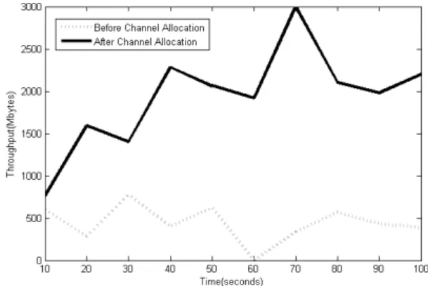
Fig. 8. Network Throughput Before/After Channel Allocation
Fig. 9. Network Throughput Comparison
Fig. 6 shows the channels used for the backbone before the channel allocation method was employed. The first console shows the channel used for router P2MT 1. It uses channel 1 to connect to router P2MT 2. The second console shows the channel used for router P2MT 2. Note that it has two interfaces. Its first interface uses channel 1 to connect to P2MT 1. Its second interface uses channel 11 to connect to P2MT 3. The third console shows the channel used for router P2MT 3. It uses channel 11 to connect to P2MT 2.
We then collect the scores from all of the routers, and run the genetic algorithm to generate new channels, which are shown in Fig. 7. The new channels are expressed as a matrix of numbers. Each row in the matrix corresponds to a router, and each column corresponds to the channel for the corresponding interface for that router. For example, the number 4 in the first row means that the first router P2MT 1 should use channel 4 for its second interface. 0 means that there is no connection for that interface. For example, the 0 in the first row of the first column means that there is no connection for the first interface of P2MT 1.
script called allocate.py. This script encapsulates all of the configuration settings for each router into JSON, and posts the JSON request to the corresponding router (see Fig. 7).
The channels after allocation are shown in Fig. 6. The first console shows the channel used for router P2MT 1. It uses channel 4 to connect to router P2MT 2. The second console shows the channel used for router P2MT 2. Note that it has two interfaces. Its first interface uses channel 4 to connect to P2MT 1. Its second interface uses channel 7 to connect to P2MT 3. The third console shows the channel used for router P2MT 3. It uses channel 7 to connect to P2MT 2.
Fig. 8 and Fig. 9 show the network throughput before and after the channel allocation algorithm was used. Before the channel allocation, the network throughput was around 285 to 778 MBytes/s. After the channel allocation, the network throughput had increased to around 761 to 2285 MBytes/s.
VI. CONCLUSION
In conclusion, we have presented a channel allocation algorithm based on a genetic algorithms for IEEE 802.11 wireless mesh networks, and an auto-config-mesh tool to deploy the channel allocations to the wireless mesh routers. For testing and evaluation purposes, we implemented the GA-based channel allocation method using real wireless mesh routers, and tested it as well as the auto-config-mesh tool in a real environment. The results provide valuable insights into the design of GA-based channel allocation algorithms for wireless mesh networks.
REFERENCES
[1] B. Raman, “Channel allocation in 802.11-based mesh networks,” in Proc. 25th IEEE International Conference on Computer Communica-tions (INFOCOM), 2006.
[2] B. Crow, I. Widjaja, J. G. Kim, and P. Sakai, “Ieee 802.11 wireless local area networks,”IEEE Communications Magazine, vol. 35, no. 9, pp. 116–126, September 1997.
[3] Turning 802.11 Inside-Out. Pravin Bhagwat, 2003.
[4] E. Brewer, “The case for technology for developing regions,”IEEE Computer, vol. 38, no. 6, pp. 25–38, June 2005.
[5] B. Hirantha Sithira Abeysekera, M. Matsui, Y. Asai, and M. Mi-zoguchi, “Network controlled frequency channel and bandwidth al-location scheme for ieee 802.11a/n/ac wireless lans: Ratop,” inProc. IEEE 25th Annual International Symposium on Personal, Indoor, and Mobile Radio Communication (PIMRC), 2014.
[6] M. Alicherry, R. Bhatia, and L. E. Li, “Joint channel assignment and routing for throughput optimization in multi-radio wireless mesh networks,” inProc. 11th Annual International Conference on Mobile Computing and Networking, 2005.
[7] J.-P. Sheu, Z.-X. Wu, C. Ma, and R. Jagadeesha, “Interference-aware channel allocation algorithm with game theoretic approach for cogni-tive radio networks,” inProc. 20th IEEE International Conference on Parallel and Distributed Systems (ICPADS), 2014.
[8] H. Balbi, N. Fernandes, F. Souza, R. Carrano, C. Albuquerque, D. Muchaluat-Saade, and L. Magalhaes, “Centralized channel alloca-tion algorithm for ieee 802.11 networks,” inProc. Global Information Infrastructure and Networking Symposium (GIIS), 2012.
[9] G. Zhang, J. Gu, and Z. Bao, “Distributed joint routing and channel allocation algorithm in cognitive wireless mesh networks,” inProc. 3rd IEEE International Conference on Broadband Network and Mul-timedia Technology (IC-BNMT), 2010.
[10] K. N. Ramachandran, E. M. Belding-Royer, K. C. Almeroth, and M. M. Buddhikot, “Interference-aware channel assignment in multi-radio wireless mesh networks,” in Proc. 25th IEEE International Conference on Computer Communications (INFOCOM), 2006. [11] S. H. Wong and I. Wassell, “Dynamic channel allocation using a
genetic algorithm for a tdd broadband fixed wireless access network,” inProc. International Conference in Wireless and Optical Communi-cations (IASTED), 2002.
[12] K. V. Subbaiah and M. Naidu, “An efficient interference aware channel allocation algorithm for wireless mesh networks,” in Proc. International Conference on Signal Processing And Communication Engineering Systems (SPACES), 2015.
[13] C. Y. Ngo and V. O. Li, “Fixed channel assignment in cellular radio networks using a modified genetic algorithm,”IEEE Transactions on Vehicular Technology, vol. 47, no. 1, pp. 163–172, February 1998. [14] P. Guo, X. Wang, and Y. Han, “The enhanced genetic algorithms for
the optimization design,” in Proc. 3rd International Conference on Biomedical Engineering and Informatics (BMEI), 2010.
[15] An Introduction to Genetic Algorithms. London: The MIT Press. Melanie Mitchell, 1999.
[16] A. Saifullah, Y. Xu, C. Lu, and Y. Chen, “Distributed channel allocation protocols for wireless sensor networks,”IEEE Transactions on Parallel and Distributed Systems, vol. 25, no. 9, pp. 2264–2274, August 2014.
[17] D. Beckmann and U. Killat, “A new strategy for the application of genetic algorithms to the channel-assignment problem,” IEEE Transactions on Vehicular Technology, vol. 48, no. 4, pp. 1261–1269, July 1999.
[18] E. Z. Tragos, A. Fragkiadakis, I. Askoxylakis, V. Siriset al., “The impact of interference on the performance of a multi-path metropolitan wireless mesh network,” inProc. IEEE Symposium on Computers and Communications (ISCC), 2011.
[19] A. P. Subramanian, H. Gupta, S. R. Das, and J. Cao, “Minimum in-terference channel assignment in multiradio wireless mesh networks,” IEEE Transactions on Mobile Computing, vol. 7, no. 12, pp. 1459– 1473, December 2008.
![Table II shows an example of the channel allocation solution matrix R. When we assign a channel c to a link between two routers i and j, we set the corresponding entries R[i, j] and R[j, i] to c](https://thumb-eu.123doks.com/thumbv2/123dok_br/16302378.186200/2.892.132.384.351.726/example-channel-allocation-solution-channel-routers-corresponding-entries.webp)