Abstract—Adaptive power control is an actual research
topic due to its use for energy saving and for improving network capacity in wireless mesh networks. By varying the transmit power level, the signal quality is affected, consequently determining which neighboring nodes can receive the packets. In this paper, we propose a new power control technique that adapts the transmissions based on the neighboring active links. It is evaluated alongside with other methods, described in the literature, for improving network capacity. We show, by simulation, that our method can improve the network throughput by up to 30% compared to the IEEE 802.11 standard MAC in a grid topology.
Index Terms—medium access control, network capacity,
power control, wireless mesh networks, WMN
I. INTRODUCTION
N wireless mesh networks, due to the sharing of the wireless transmission medium, a medium access protocol (MAC) is needed in order to reduce the collisions to a certain level. A commonly used MAC protocol is based on the IEEE 802.11 standard.
Because it was originally intended for WLANs, it does not always cope with some characteristics of WMNs: a high network density; highly energy constrained, battery powered network nodes; and the increased usage of WMNs in real-time applications that have latency constraints or require high throughput. The problems raised by this MAC are due to the handshake scheme used and to the constant transmit power level. It results in an inefficient spatial reuse, because all nodes in the carrier sense range of the transmitter-receiver pair have to defer their transmission in order not to cause any interference. Also, when starting a transmission, the distance between the transmitter and receiver is not taken into account, resulting in an inefficient energy use alongside the spatial reuse problem [1].
One way to overcome these drawbacks is by power control. The adaptive power control problem in wireless mesh networks is that of choosing the transmit power level for each packet at each transmitting node, in a distributed fashion. Its intended purpose is to increase the network capacity, while consuming energy in an efficient way. Previous research has been done concerning this method.
Manuscript received March 06, 2011; revised April 08, 2011.
N. Botezatu is a PhD student at the Faculty of Automatic Control and Computer Engineering, “Gh. Asachi” Technical University of Iasi, Romania (e-mail: [email protected])
R. Dhaou is with the University of Toulouse, IRIT-ENSEEIHT, 2 rue Charles Camichel, BP7122, 31071 Toulouse Cedex 7, France (e-mail: [email protected])
In [2], the authors propose a scheme that determines the minimum power level for transmitting the DATA/ACK packets. Also, the power level is periodically increased in order to defer neighboring nodes that may interfere. Although this protocol does not achieve any throughput improvements, it yields energy savings.
Another approach to the power control problem is presented in [3]. The network nodes are clustered in neighboring groups that may need the same transmit power level. This is achieved by adjusting the transmit power level for the DATA/ACK packets based on the average distance from the transmitter to all current neighbors. Results show that, in mobile networks, the energy consumption decreases, although the throughput remains approximately equal to the one corresponding to the standard 802.11 MAC.
More recent research [4] proposes a method in which the nodes that overhear RTS/CTS packets can make a decision to start their own data transmission, at the same time. The process is based on extra information included in the control packet headers, which provide a status for the neighboring nodes: minimum transmit power, maximum transmit power and the NAV value. This MAC protocol achieves higher throughput than the 802.11 MAC.
In Section II we present our proposed solution and in Section III we describe a case study, alongside the obtained results. Section IV highlights some future research perspectives.
II. SOLUTION DESCRIPTION
Before introducing our proposed power control mechanism, some prerequisites are needed, which concern some IEEE 802.11 MAC elements.
A. MAC 802.11 basics
The IEEE 802.11 standard specifies DCF (Distributed Coordination Function) as the default medium access scheme. It employs a Multiple Access with Collision Avoidance (CSMA/CA) algorithm [5].
In order to explain the medium access mechanism, we must define the following terms: reception range, carrier sense range and interference range.
When a node is in the reception range (RxR) of a node, it can receive correctly packets from the source.
All transmitters in the interference range (IR) can corrupt the reception of a packet from the designated source due to a high SNR level. It varies with the distance between the transmitter and the receiver and with the SNR threshold. Finally, the carrier sense range (CSR) is the area in which a node can sense the transmission of a packet, but cannot decode it (i.e. is the range in which the physical
Adaptive Power Control in 802.11 Wireless
Mesh Networks
N. Botezatu, and R. Dhaou
I
Proceedings of the World Congress on Engineering 2011 Vol II WCE 2011, July 6 - 8, 2011, London, U.K.
ISBN: 978-988-19251-4-5
ISSN: 2078-0958 (Print); ISSN: 2078-0966 (Online)
carrier sensing is done). We consider it not to include the RxR.
The carrier sensing is performed at both the physical layer and the MAC layer. The latter case is known as Virtual Carrier Sensing and is enforced using an RTS/CTS/ACK handshake. It uses the duration of the packet transmission, this information being included in the RTS, CTS and DATA packet headers. This information is used to defer the transmissions of other neighboring nodes and for the source node to know when it would receive an ACK frame. Every node in an IEEE 802.11 network has a Network Allocation Vector (NAV), which specifies the duration of the ongoing transmissions. The NAV is updated at every reception of a RTS, CTS or DATA packet, even if the receiving node is not the intended recipient. The channel is considered busy if either of the two carrier sensing methods indicates ongoing transmissions.
B. Max-Min protocol
One of the simplest solutions that addresses the power control problem, by modifying the IEEE 802.11, is named Max-Min or Basic protocol [2], [3], [6]. It uses RTS and CTS packets transmitted at the highest possible power level and DATA and ACK packets transmitted at the minimum power level necessary to reach their destinations.
The RTS-CTS handshake is used to decide the transmission power for subsequent DATA and ACK packets based on (1). The RTS and CTS packets are always sent at the maximum power level. When the node that started the handshake receives the CTS, it calculates the needed power level PTDATA/ACK based on the received power level PRCTS
and on the transmitted power level PTRTS. RxTh is the
minimum necessary signal strength to correctly receive a data packet.
Th CTS RTS ACK
DATA
Rx
PR
PT
PT
/=
⋅
(1)When the neighboring nodes of the transmitter-receiver pair receive an RTS or CTS, they set the NAV to match the duration of the DATA and ACK packets. Although this situation is favorable, the nodes that have the transmitter in their CSR, will set the NAV to a duration equal to EIFS. When the pair starts to transmit the DATA and ACK packets at a lower power level, they might not be included any more in the CSR of the nodes that previously detected them. As a result, nodes, close enough to interfere, may start a transmission, at the maximum power level, that collides with the DATA and ACK packets currently being transmitted. This results in throughput degradation and higher energy consumption, due to retransmissions.
C. CcPc-MAC protocol
Our solution is based on the same idea of power control. The RTS packets are sent with the highest transmitting power available. For the CTS ones, we take into account other concurrent transmissions, while the DATA and ACK packets are sent with the lowest possible power level. In order to address the problem introduced by the extra collisions, the data transmission sessions are started selectively, based on two factors: the distance between the transmitter and the receiver; and information about the neighboring nodes that may interfere with the transmission. This raises the need to evaluate the effectiveness of the
RTS-CTS handshake, in order to see how the reception is affected by the nodes in the IR.
As stated before, the IR varies with the distance between the transmitter and the receiver. In order to express this relation, we start from two premises: the use of the Two-Ray Ground as propagation model (2); and the assumption that the network is homogenous, meaning that all the nodes have the same radio parameters.
4 2 2
d
hr
ht
GR
GT
PT
PR
=
⋅
⋅
⋅
⋅
(2)PR is the received power level, PT is the transmit power level, GT and GR are the antenna gains, ht and hr are the heights of the two antennas, d is the distance between the transmitter and the receiver [7].
We assume a transmission between two nodes, d meters away, and an interfering node, di meters away. The
signal-to-noise ratio (SNR) at the receiver is given by the proportion of the two signals, at the receiver. For the designated signal to be valid, the SNR, between it and the interfering one, must be above a certain threshold, SNRTh.
Based on (2), the SNR at the receiver is a ratio of the distances between the nodes (3).
Th
i
SNR
d
d
SNR
⎟
≥
⎠
⎞
⎜
⎝
⎛
=
4
(3) This means that, in order to receive a valid packet, the
interfering nodes must be at least 4
SNR
Th⋅
d
meters awayfrom the receiver. In other words, the IR is expressed as (4).
d
SNR
IR
=
4 Th⋅
(4)As shown in [8], the IR is not always covered by the RTS-CTS handshake. This is the mechanism that stands for the deficiency of the Max-Min scheme, where the IR remains constant, while the RxR and CSR decrease due to the power control.
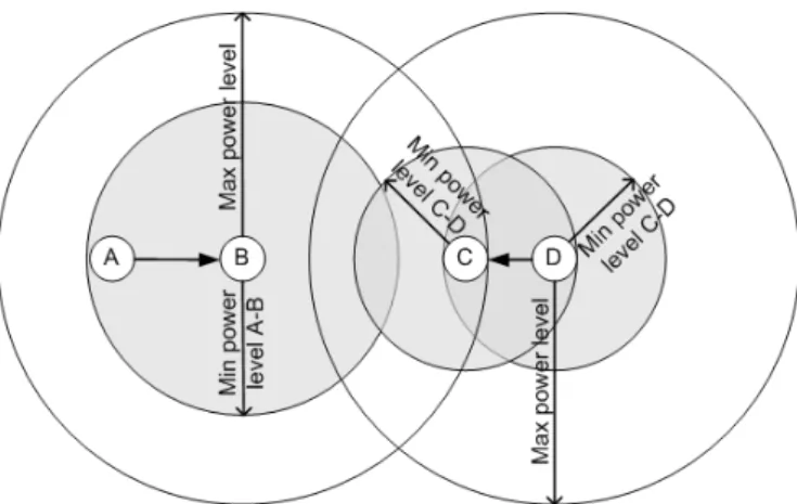
In order to describe how our CTS conservative power control protocol (CcPc-MAC) addressed the interference problem, we start from an example situation (Fig. 1). When nodes A and B perform the RTS-CTS handshake, node C logs the information regarding the two nodes: the distance between them, the power levels used and the duration of the operation. Next, we presume that the power level needed for the transmission of the DATA and ACK packets is low enough, for node C only to sense the carrier. If node D wants to start a transmission to node C, after node C receives the RTS, it determines if it can transmit a CTS packet with a power level that does not interfere with the
A-Fig. 1. Sample transmit power adaptation.
Proceedings of the World Congress on Engineering 2011 Vol II WCE 2011, July 6 - 8, 2011, London, U.K.
ISBN: 978-988-19251-4-5
ISSN: 2078-0958 (Print); ISSN: 2078-0966 (Online)
TABLEI
PHYSICAL INTERFACE PARAMETERS
Maxim data rate 2 Mbps
SNR Threshold 10 dB
Receive Threshold (RxTh) 3.6 ∙10 -7 mW Carrier Sense Threshold (CSTh) 1.5 ∙10 -8 mW Propagation model Two Ray Ground
TABLEII TRANSMIT POWER LEVELS
Power level (mW) Receive Threshold (m)
Carrier Sense Threshold (m)
9 105.6 232.5 50 162.2 356.9 210 232.2 511
TABLEIII
INTERFERENCE RANGE FOR VARIABLE POWER LEVELS
Transmit power level (mW)
Interference transmission power level (mW)
Interference range 9
9
1.78*d
50 1.16*d 210 0.81*d
9
50
2.73*d
50 1.78*d 210 1.24*d
210 210 -
B transmission. Of course, the power level must be high enough to reach D. If none of the available power levels are suited, node C discards the RTS request and does not send a CTS. As with the IEEE 802.11 standard, if node D does not receive the CTS in a time window, it tries to send the RTS for a number of times. If the A-B transmission finishes, node C responds to the request, otherwise the node D drops the data packet.
III. CASE STUDY
In order to test the proposed method, we evaluated its performance through computer simulation. The simulation environment used was ns-2 (v2.34) [9]. Alongside CcPc-MAC, we implemented the Max-Min protocol.
A. Experimental setup
We used a grid topology of 100 nodes, evenly distributed at 50 meters on both axes (10 by 10 nodes). The simulation parameters concerning the wireless PHY match those of the 914 MHz Lucent WaveLAN DSSS interface, as it is the default setup for the simulator, the only difference being the use of variable values for the transmission power level. The most relevant parameters of the physical interface are presented in Table I.
For the evaluation of both power control mechanisms, there were used three power levels, presented in Table II. The 210 mW power level is the default one for the simulated interface and was also used in the simulations for the 802.11 MAC.
The data source was represented by a UDP/CBR generator with a data rate of 1 Mbps and a packet size of 512 bytes; for packet routing we used an implementation of the DSDV protocol.
In the case of the CcPc-MAC method, the threshold values for sending the CTS packets were chosen based on the variation of the IR for combinations between the
transmit power level and the transmit power level of the interfering signal, as shown in Table III. The RTS Retry parameter [5] was set to the default value of 7, for all evaluated methods.
For every experimental setup, the simulation session included 50 simulation runs over a period of 150 seconds each, while the transmitter-receiver node pairs were chosen randomly; also, the number of pairs was varied in order to evaluate the performance function of the network load. In order to reduce the influence of the routing protocol, on the network performance, the node pairs were chosen in such manner that they could reach directly each other, at the maximum power level.
The resulting trace files were processed in order to give the aggregate throughput, expressed as the average rate of successfully received packets over the simulation period, measured in bits per second (bps). Also, the loss rate was determined, as the ratio between the total simulated packets and the packets not delivered, due to collisions or lack of CTS reply. A third network capacity metric was considered the average latency. It represents the time elapsed between the generation of a data packet and the reception by the intended node.
B. Simulation results
Fig. 2 presents the throughput variation with the number of transmitter-receiver pairs for all three methods evaluated. For low density networks (i.e. less transmitter-receiver pairs), by using a constant power level we obtained better results than using one of the adaptive schemes. This is due to the extra collisions induced by the asymmetry of the network. But with the increase in transmit density, the higher number of pairs that transmit data at the same time compensate for data retransmission, resulting in a higher throughput. The CcPc-MAC obtained an average improvement of 30% in throughput compared to the 802.11 MAC.
The results obtained for the loss rate support the claim of increased collisions, concerning the power control protocols (Fig. 3). Our solution does not compensate entirely for the reduction of collisions, compared to the Max-Min protocol, due to the handshake sessions dropped as a result of the absence of a CTS reply.
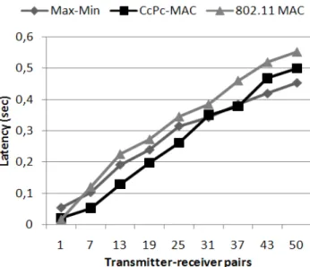
Max-Min turned out to have the worst results for low density networks, concerning the latency (Fig. 4). After the threshold of 37 pairs, it obtained the lowest values for the
Fig. 2. Aggregate throughput variation with the number of active pairs.
Proceedings of the World Congress on Engineering 2011 Vol II WCE 2011, July 6 - 8, 2011, London, U.K.
ISBN: 978-988-19251-4-5
ISSN: 2078-0958 (Print); ISSN: 2078-0966 (Online)
latency. Our method performed well compared to the 802.11 MAC and the Max-Min method, obtaining an average latency decrease of 32%, respectively 19%.
IV. CONCLUSIONS AND FUTURE WORK
In this paper we have proposed an adaptive power control mechanism, based on the IEEE 802.11 MAC. It used different transmit power levels for the RTS/CTS packets and for the DATA/ACK ones. Further, in order to reduce the effects of hidden nodes, receivers selectively respond with CTS packets, based on their interference ranges and on neighboring active transmissions. Results show improvements of 30% in throughput and latency compared to the 802.11 MAC.
Future research includes the study of CcPC-MAC in mobile networks. Also, the impact on the upper layer routing protocols must be determined, due to the creation of asynchronous links in the network. Furthermore, we want to study the impact on energy consumption, a critical factor in battery powered wireless nodes.
REFERENCES
[1] V.P. Mhatre, K. Papagiannaki, and F. Baccelli, “Interference Mitigation through Power Control in High Density 802.11 WLANs”
in 26th IEEE International Conference on Computer Communications,
Anchorage, 2007, pp. 535-543.
[2] E.-S. Jung, and N.H. Vaidya, “A Power Control MAC Protocol for Ad Hoc Networks” in Proc 8th Annual International Conference on
Mobile Computing and Networking, Atlanta, 2002, pp. 36-47
[3] H.-H. Chen, Z. Fan, and J. Li, “Autonomous Power Control MAC for Mobile Ad Hoc Networks”, in EURASIP Journal on Wireless
Communications and Networking, vol. 2006, issue 2, April 2006, pp.
1-10.
[4] P. Li, X. Geng, and Y. Fang, “An Adaptive Power Controlled MAC Protocol for Wireless Ad Hoc Networks”, in IEEE Transactions on
Wireless Communications, vol. 8, no. 1, Jan. 2009, pp. 226-233.
[5] Wireless LAN medium access control (MAC) and physical layer
(PHY) specifications, IEEE Standards Working Group, 1999.
[6] H. Gossain, C. de M. Cordeiro, and D. P. Agrawal, “Energy efficient MAC protocol with spatial reusability for wireless ad hoc networks”,
in International Journal of Ad Hoc and Ubiquitous Computing, vol. 1,
issue 1/2, Nov. 2005, pp. 13-26.
[7] T. Rappaport, Wireless Communications: Principles and Practice, 2nd
Edition, Upper Saddle River: Prentice Hall, 2002, pp. 120-125.
[8] Kaixin Xu, M. Gerla, Sang Bae, “How effective is the IEEE 802.11 RTS/CTS handshake in ad hoc networks?” in Global
Telecommunications Conference 2002, vol. 1, pp. 72-76.
[9] The Network Simulator – ns-2, 2009, http://www.isi.edu/nsnam/ns/. Fig. 3. Loss rate variation with the number of active pairs.
Fig. 4. Average latency variation with the number of active pairs.
Proceedings of the World Congress on Engineering 2011 Vol II WCE 2011, July 6 - 8, 2011, London, U.K.
ISBN: 978-988-19251-4-5
ISSN: 2078-0958 (Print); ISSN: 2078-0966 (Online)