www.j-sens-sens-syst.net/3/87/2014/ doi:10.5194/jsss-3-87-2014
©Author(s) 2014. CC Attribution 3.0 License.
Open
Access
JSSS
Journal of Sensors and Sensor SystemsChain of refined perception in self-optimizing assembly
of micro-optical systems
S. Haag1, D. Zontar1, J. Schleupen1, T. Müller1, and C. Brecher2 1Fraunhofer Institute for Production Technology IPT, Aachen, Germany
2Chair at the Laboratory for Machine Tools and Production Engineering (WZL) at RWTH Aachen University,
Aachen, Germany
Correspondence to:S. Haag ([email protected])
Received: 5 December 2013 – Revised: 5 March 2014 – Accepted: 21 March 2014 – Published: 14 April 2014
Abstract. Today, the assembly of laser systems requires a large share of manual operations due to its com-plexity regarding the optimal alignment of optics. Although the feasibility of automated alignment of laser optics has been shown in research labs, the development effort for the automation of assembly does not meet economic requirements – especially for low-volume laser production. This paper presents a model-based and sensor-integrated assembly execution approach for flexible assembly cells consisting of a macro-positioner covering a large workspace and a compact micromanipulator with camera attached to the positioner. In order to make full use of available models from computer-aided design (CAD) and optical simulation, sensor systems at different levels of accuracy are used for matching perceived information with model data. This approach is named “chain of refined perception”, and it allows for automated planning of complex assembly tasks along all major phases of assembly such as collision-free path planning, part feeding, and active and passive alignment. The focus of the paper is put on the in-process image-based metrology and information extraction used for identifying and calibrating local coordinate systems as well as the exploitation of that information for a part feeding process for micro-optics. Results will be presented regarding the processes of automated calibration of the robot camera as well as the local coordinate systems of part feeding area and robot base.
1 Introduction
Optical systems and lasers belong to high-technology sec-tors with high technical and economic potential in the near future. Especially, the laser industry is regarded to be highly innovative with a leverage effect on other industrial branches. New and improved products are developed and brought to the market frequently. Diode laser systems have a market share of about 50 %1, and they are characterized by good energy ef-ficiency and small size on the one hand and a relatively large beam divergence angle on the other. The latter requires the challenging assembly of collimation optics. The scope of this paper addresses the assembly of micro-optics and especially the assembly of collimation optics in diode laser systems.
1LaserFocusWorld, LASER MARKETPLACE 2013, January
2013.
tributed multi-agent systems have been implemented in or-der to provide flexible architectures for assembly execution. Further flexibility can be achieved through interaction of a machine with its environment. This requires sensor integra-tion allowing the percepintegra-tion of the environment (Russell et al., 2010).
Higher flexibility and sensor integration lead to higher complexity, which is a challenge regarding the efficient plan-ning and commissioplan-ning of alignment processes for optics. The work presented in this paper is motivated by the current discrepancy between the benefits of flexibility and sensor in-tegration and the increased complexity. Therefore, this paper shows how 2-D bin-picking of micro-optics in part feeding can efficiently be realized and embedded in a model-based control scenario using low-cost hardware.
2 Chain of refined perception
The integration of sensors allows the perception of crucial process data and its use for optimizing individual steps as well as the overall result of the assembly task. For mak-ing full use of available models such as geometric model of the product and the assembly cell from computer-aided design (CAD) or the optical setup from ray-tracing simula-tion, coarse information from the large workspace and high-resolution information from local regions has to be evalu-ated. In most cases it is inconvenient or even impossible to use high-precision sensors, which cover a large workspace at the same time.
This section introduces the architecture of flexible assem-bly systems and the principles of self-optimizing optics as-sembly on which the concept of this work is built. The final part of this section introduces the chain of refined perception, which is applied for the model-based execution of optics as-sembly.
2.1 Flexible assembly cell concept for micro-optical systems
Flexible assembly systems for micro-optics usually combine a macro-workspace covering a large area by a robot or gantry with a micro-workspace in which a micromanipulator locally carries out sensor-guided high-resolution motion in the sub-micrometer range (Brecher et al., 2012).
In previous research projects, modular micromanipulators with three or six degrees of freedom have been developed
viding the required flexibility regarding the control architec-ture of a flexible assembly system.
2.2 Self-optimizing assembly of laser optics
One focus of the research in the Cluster of Excellence “In-tegrated Production Technology for High-wage Countries” at RWTH Aachen University2 is put on self-optimizing as-sembly systems, which aim for the reduction of planning ef-forts for complex and sensor-based assembly tasks (Brecher, 2012). Self-optimizing assembly of laser optics is applied for the production of high-quality laser modules coping with fi-nite positioning accuracy of the actuation system, noisy per-ception, and tolerances of laser beam sources and optics. Therefore, model-based approaches for assembly execution under the presence of uncertainties are investigated.
Conceptually, self-optimizing systems follow a three-step cycle. Firstly, the current situation is analyzed considering the objective of the task, the current state of the assembly system including the product as well as a knowledge base holding additional information provided prior to assembly or collected during assembly execution. Secondly, internal ob-jectives such as reference values for internal closed-loop con-trols are adapted based on reasoning on the analysis carried out in the previous step. This step goes beyond the classical definition of closed-loop controls and adaptive closed-loop controls. In a third step, self-optimizing systems adapt their behavior either through parameter adaption or through struc-tural changes.
Hence, key aspects of self-optimizing assembly systems are model-based control and sensor integration. Model-based control allows automatisms during the planning phase and therefore drastically reduced planning times. Yet the ap-proach requires the use of sensors in order to identify and compensate differences between ideal models and real-world situations.
Figure 1 shows the reduced ontology of a model-based self-optimizing assembly system. Different types of models such as product models (e.g., geometry, optical function), production system models (e.g., kinematic chains) as well as process knowledge and system objectives provide infor-mation for the cognition unit to select and configure algo-rithms and program logic. For example, the product model might provide a certain geometrical or optical constraint to
Figure 1.Reduced ontology of a self-optimizing assembly system.
be fulfilled by an assembly step. The cognition unit selects a certain type of mounting sequence consisting of a stan-dardized sequence of steps (mounting template) such as part pickup, dosing of adhesives, active alignment, etc. In the con-text of this paper the part pickup is of special interest. The rough coordinates of the optical element can be retrieved from the geometrical model of the production system. The small size and the presence of uncertainties require the local-ization of the part with a precision sufficient for part pickup. This paper presents a sensor-guided approach for localizing micro-optical parts realized on a low-cost robot-based as-sembly station.
2.3 Chaining of process steps in micro-optical assembly
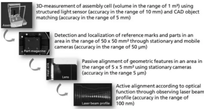
In order to overcome the gap between ideal models and un-certain reality, crucial assembly steps are implemented based on sensor guidance. Individual tasks during the assembly of micro-optics such as the pickup of parts or alignment of op-tics require different levels of accuracy ranging roughly from 10 mm measuring accuracy achieved by low-cost structured light sensors down to 100 nm positioning accuracy achieved through active alignment. Figure 2 shows the concept of a chain of refined perception as propagated by the work pre-sented. For carrying out process steps, this concept uses sev-eral means of perception at different levels of granularity. The objective of one process step is to transform the assembly state to the tolerance level of the subsequent process step. The approach enables the advantages of planning complete assembly tasks based on models with the flexibility and pre-cision of sensor-integrated systems. Figure 2 shows the chain of refined perception for the case of micro-optical assembly. In the top level it covers a large workspace in the range of one or more cubic meters for autonomously planning collision-free paths of the macro-positioner. In the bottom level, a mo-tion resolumo-tion for optical alignment in the range of 10 nm is possible.
For the task of collision-free path planning, software tools such as MoveIt! as part of the ROS package3have been de-veloped in the robotics community. The work related to this paper applies such software in combination with structured
3See http://moveit.ros.org/wiki/MoveIt!.
Figure 2.Chain of refined perception for self-optimizing
assem-bly of micro-optical systems indicating roughly the volume or area covered by measurements as well as the measurement accuracy achieved.
light sensors such as Microsoft Kinect. The environment can be scanned in 3-D with such sensors. Additional point cloud processing software tools4allow the matching of CAD mod-els with the detected point clouds. The result is a collision model that allows the planning of collision-free paths.
For tasks such as 2-D bin-picking of micro-optical com-ponents, local coordinate systems need to be calibrated with reference to each other. Figure 3 shows a typical setup with a fixed camera and a mobile camera (the mobile camera and the micromanipulator it is attached to are carried by a posi-tioning system such as a robot or a gantry). The fixed camera and its objective cover a large area such as a part carrier. The mobile camera covers a much smaller area intended for de-tecting local reference marks. The detection of defined ref-erence marks allows the calibration of the cameras and their spatial relation.
Passive alignment is a step usually required prior to active alignment, and it is based on the detection of reference marks or geometric features using charge-coupled device (CCD) chips. During passive alignment parts are pre-positioned with reference to each other so that the initial starting point for active alignment is within a certain tolerance with high prob-ability.
In the context of optics assembly, the task of active align-ment accounts for the quality of the optical system. In the case of collimation optics, an optical measurement setup and a CCD chip are used for determination of the current state of alignment. Alignment algorithms have been and currently are subject to recent research activities (Brecher, 2012; Haag and Härer, 2012; Pierer et al., 2011; Miesner et al., 2009).
3 Calibration of stationary and mobile camera
As depicted above, two camera systems are used in the setup for the calibration of the positioner coordinate system with reference to the local coordinate system defined by local
and mobile camera systems (left) and photography of the part mag-azine setup including dark field illumination using a ring light and the micromanipulator (right).
reference marks. The first camera is fixated perpendicular above the part carrier. The second is mounted to the micro-manipulator, which is attached to the macro-positioner (cf. Fig. 3). In order to use image data as input for further cal-culations, both cameras have to be calibrated first. The cali-bration process allows compensating optical and perspective distortion and determining a scaling factor between image pixel and real-world metrics.
3.1 Calibration of stationary camera
The stationary camera system is equipped with a common entocentric optic and is appointed to monitor parts on the Gel-Pak magazine (part carrier). The predominant kinds of distortion consist of a radial barrel distortion, which is gen-erally associated with the deployed kind of lens, and a trape-zoidal distortion resulting from a misalignment of the cam-era with respect to its optimal perpendicular orientation. The scaling factor is calculated for the surface plane of the Gel-Pak because it depends on the object’s distance to the camera. Determining and compensating camera distortion is a com-mon task in computer vision. Hence, algorithms are widely available as frameworks in many programming languages.
The scaling factor can be obtained during the determina-tion of the distordetermina-tion or the local coordinate system simply by comparing known physical features like the calibration pat-tern or the distance between two reference marks with their representation in the image.
The calibration process has to be carried out when the po-sition or orientation of the stationary camera changes.
3.2 Calibration of mobile camera
The mobile camera system is equipped with a telecentric lens to provide local image data of components during assembly tasks. Due to specific properties of telecentric lenses, there is no need to compensate any imaging deformations caused by perspective. Therefore, the calibration process only includes the identification of the relationship between the camera’s lo-cal coordinate system and the robot’s tool center point (TCP) (cf. Fig. 4).
x
TCPFigure 4.Relationship between the image and TCP coordinate
sys-tem.
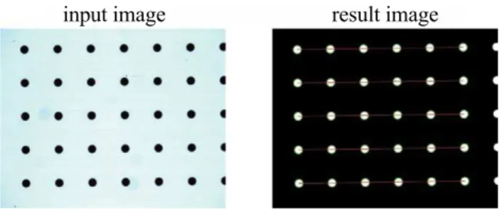
input image result image
Figure 5.The scaling factor is obtained by comparing the detected
pattern with known physical features (center point distances).
The telecentric lens is mounted approximately at the cen-ter of the robot’s TCP while the fixed focus plane is tuned to be aligned with an attached gripper. For a mathematical coor-dinate transformation, four parameters have to be identified: thexandyoffset of the image center from thezaxis of the TCP, the camera orientation described by the angle between bothxaxes and finally the scaling factor to transform pixels into millimeters.
To obtain the scaling factor, the camera is positioned above a calibration pattern (dot target) with known physical fea-tures. The distance between two points in the image is then compared to its physical equivalent (cf. Fig. 5).
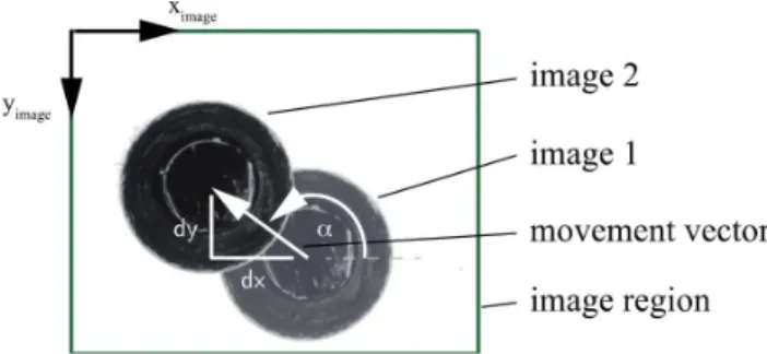
The angular offset is determined in a two-step approach. First, the robot camera is positioned above a reference mark. The camera image is then analyzed to determine its center point, which is stored along with the current robot coordi-nates. For the second step the robot is moved in a plane so that the reference mark stays in the image region, which will be analyzed again. The orientation can then be calculated by comparing the vector described by the movement of the robot with the movement of the reference mark in the image (cf. Fig. 6).
Figure 6.Images before and after a movement have been over-laid. The camera orientation is calculated by comparing the robot’s movement and the vector described by the reference mark.
Figure 7.A reference mark describes a circle while the camera
system is rotated. The pivot point identifies thezaxes of the TCP.
a circle that can be fitted to measured points. Its center point depicts the origin of thexandyaxes of the TCP (cf. Fig. 7).
3.3 Calibration of local coordinate systems
In order to calculate the position and orientation of compo-nents in robot coordinates, a local coordinate system has to be defined first. Therefore two reference marks have been placed alongside the Gel-Pak to identify the origin and the direction of theyaxes. Thezaxis is defined to be perpen-dicular to the surface pointing upwards. Finally, thexaxis is positioned to complete a right-handed coordinate system.
The reference marks must be positioned in the image area of the stationary camera, in order to be identified and used to describe parts on the Gel-Pak in a local coordinate sys-tem. However, the distance of both reference marks should be maximized in order to minimize any error on the mea-suredyaxis orientation.
The local coordinate system can be automatically mea-sured in positioner coordinates by moving the positioner with its mobile camera above each reference mark. Image data can then be analyzed to detect the center point of each reference mark. Based on the calibration of the mobile camera, coor-dinates can further be transformed into TCP coorcoor-dinates and finally into positioner base coordinates.
Figure 8.Hybrid assembly setup consisting of a SCARA kinematic
as macro-positioner and a micromanipulator for fine alignment. The software window shows the result of image processing (detection of reference marks and localization of optics of different types).
4 2-D Bin-picking of micro-optical components
Part identification has been implemented as a stand-alone ap-plication. Through standard networking APIs, process con-trol scripts can retrieve detailed information about every de-tected part on the magazine (cf. Fig. 8). OpenCV has been used for image processing. See Laganière (2011) and Brad-ski (2000) for reference.
Gel-Paks® provide a convenient way to handle optical
components during transport. Due to a proprietary elas-tomeric material, parts can be placed freely on the carrier and kept in position to ensure safe transportation and storage. Hence, this kind of magazine is a standard way of presenting optical components. Pickup positions can no longer be stati-cally defined and therefore have to be identified through sen-sor evaluation. In the setup presented in this paper, a camera fixated above the Gel-Pak®covers the complete lens
presen-tation area as well as a set of reference marks in its field of view (cf. Fig. 9). Applying image processing, optics can be located in the local 2-D coordinate system. In order to carry out the robot-based pickup, the local coordinate system needs to be calibrated with respect to the positioner’s base coordi-nate system as explained above.
4.1 2-D localization of micro-optical components
Figure 9.Setup for detecting and localizing randomly positioned optical components on a Gel-Pak®vacuum release tray using dark
field illumination (ring light).
Figure 10.The center image shows the enhanced contrast achieved
through dark field lighting. The right diagram presents a corre-sponding normalized intensity profile. The left drawing explains the separation of blobs using dark field illumination on a cylindrical lens (only one direction of illumination is illustrated): only the rays hitting a specific region of the cylindrical surface will be reflected into the camera. This phenomenon occurs on both sides of the GRIN lens so that there are two separated blobs in image processing.
also suitable to distinguish and group parts. Formed groups can finally be mapped to templates, which have to be config-ured only once for every new component type.
Part descriptions based on salient points are not suitable because of small and mostly homogenous surfaces, which do not offer many features.
The image segmentation is based on binary threshold-ing with a watershed algorithm to achieve accurate edges. In order to enhance the contrast between the Gel-Pak and mostly transparent optical components, dark field lighting has been introduced in the experimental setup. Occasionally, parts such as cylindrical GRIN optics lead to separated blobs, which have to be combined in a postprocessing step. This has been implemented as a heuristic rule that combines closely lying blobs (cf. the two deflections in the plot of Fig. 10). The separation of the blobs is caused by the dark field illu-mination and the reflection on the cylindrical surface of the GRIN lens.
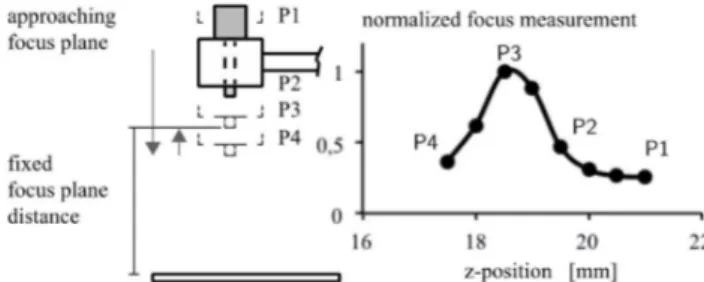
Figure 11.The left model illustrates the proceeding of a focus
mea-surement. On the right side normalized focus measurements are plotted against thezcoordinate of the robot. Measurements start above the focus plane, so the measurement points were taken from right to left.
4.2 Height measurement through variation of focus
Information on the stationary camera can only be used to ob-tain two-dimensional information about the position and ori-entation of a part. For a fully automated process, the height information has to be detected as well.
Due to the fact that the focus plane of the mobile camera is in a fixed and known distance to the lens, focus measure-ments can be utilized to determine thezcoordinate of an in-vestigated surface in comparison to an autofocus feature of a camera. Therefore, the positioner is moved in small steps towards the surface of the Gel-Pak. At each step the cam-era image is analyzed. In Nayar and Nakagawa (1990) and Firestone et al. (1991), different algorithms are presented to quantify the focus quality. The presented results are based on the Laplace operator (sum of second partial derivatives). The focus of an image correlates with the smoothness of edges in the image, which can be extracted with a Laplace filter. To weaken the effect of noise, the Laplacian of Gaussian fil-ter is applied to the investigated image region. The focus is then quantified by the weighted average of the obtained pixel intensity. In Fig. 11 normalized focus measurements are plot-ted against thezcoordinate of the robot. The focus plane is determined by the absolute maximum, which can be numer-ically calculated.
Figure 12.Image data of the stationary camera are shown. Three regions (ROI, red) are used to isolate details of interest. Identified parts(a–d)are grouped and colored by their type (GRIN, HR).
5 Evaluation of results
In the following, results regarding the camera calibration as well as the part localization processes will be presented. In the case of camera calibration, two measurements of 40 rep-etitions have been carried out. Between measurements the mobile camera has been unmounted from the mechanical in-terface and remounted again. Results are summarized in Ta-ble 1.
At a 6σlevel, the scaling factor error accounts for an
abso-lute error of less than 0.02 %. The 6σlevel for the orientation
was identified at 0.2112 degrees, which is a sufficient value for micro-optical part pickup. The 6σlevel of theX–Yoffset
is below an error of 20µm. According to these first results, calibration is sufficiently precise for the task of micro-optical part pickup. For more reliable results, more changeover sce-narios need to be carried out. The quality of calibration is strongly determined by the repeatability of the positioning system. Calibration of the mobile camera should be carried out after each camera changeover.
Using a single calibration configuration of the stationary camera, part localization has been carried out. The localiza-tion of an individual GRIN lens for 40 times has led to 6σ
levels of 1.5µm, 2.2µm for theX–Y offset.
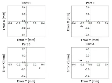
Detected parts are grouped and colored for convenience as shown in Fig. 12. After calibrating the local coordinate sys-tem, the positioner is moved above each detected component. The image from the mobile camera is then processed in or-der to evaluate the achieved precision. The component center is therefore detected in analogy to the algorithm of the sta-tionary camera and then compared to the image center. Ex-emplary results are given in Fig. 13. Positioning errors inX andYdirection are obvious. The results show that part of the error seems to be systematic depending on the corner of the
Figure 13. The identified parts of Fig. 12 have each been
ap-proached by the robot in a way that the image center of the mobile camera is overlaid with the center point of each part.
part magazine that was approached by the robot. All of the error offsets are within a range of 70µm (most of them even within a range of 30µm). One explanation for this behavior is that the robot used was in prototype stadium during the work and that kinematic transformations on the robot con-troller do not precisely correspond to the actual kinematic structure. The repeatability of the robot is sufficient for the pickup process.
The implemented image-based part localization and iden-tification allows for a reliable pickup process for the investi-gated optical components. Currently, height information for each component type is provided by the operator or an under-lying geometrical model. This ensures collision avoidance since the presented measurement via focus determination needs further investigation. The work has shown that a de-pendency exists between the surface structure of the optical component and the quality of the height measurement. For well-structured surfaces, the Laplacian approach leads to ac-ceptable results. Also, the Tenengrad algorithm as mentioned in Nayar and Nakagawa (1991) performed well. Tenengrad is based on two Sobel operators calculating gradients in horizontal and vertical directions. A 6σ level of 28.2µm
Figure 14.The plot shows a single measurement run determining the focus number calculated by the Tenengrad algorithm at a 0.2 mm step size. For statistical analyses, thezcoordinate of the surface has been determined 40 times by an autofocus algorithm.
6 Summary and outlook
The paper presented a concept of chaining process steps where each step transforms the assembly state to the next more granular level and named it “chain of refined percep-tion”. This concept was motivated and conceptually embed-ded in the context of self-optimizing micro-optical assembly systems. Such systems strongly utilize model-based control architectures, which need continuous matching with mea-surement data. Model-based control is an enabler for au-tomated planning and optimization algorithms such as path planning. Sensor integration is still required to meet the pre-cision requirements.
In more detail, techniques necessary for a computer-vision-based feeding of optical components have been pre-sented and evaluated. Implemented in manual laboratory pro-cesses, this allows for a convenient way to support operators. In an automated and self-optimizing scenario, it completes the chain of refined perception. A reliable calibration rou-tine has been presented for identifying camera parameters such as perspective distortion and for determining the scal-ing factor between image pixels and real-world metrics. An-other routine was depicted for calibrating a local coordinate system with respect to the positioner base coordinates. Such calibration allows for picking up randomly aligned optical components. This approach was enhanced by a strategy for identifying thezcoordinate of a plane through a sequence of images collected by the mobile camera attached to the tool center point. Results of this work were presented by
depict-Focus strategy 6σlevel
Tenengrad (0.5 mm steps) 29.4µm Tenengrad (0.2 mm steps) 18.0µm Laplace (0.5 mm steps) 48.0µm Laplace (0.2 mm steps) 28.2µm
ing the achieved positions in comparison with the ideal target positions.
The “chain and refined perception” will be established as an approach in further research activities focusing on the ef-ficient planning and commissioning of flexible micro-optical assembly systems. Future work aims for a product-centric approach by establishing a formalized product description similar to the descriptions in Whitney (2004) for mechanical assemblies and by deriving the assembly execution logic au-tomatically leading to drastically reduced planning and com-missioning efforts.
Acknowledgements. Research in the Cluster of Excellence for
“Integrative Production Technology for High-wage Countries” at RWTH Aachen University is funded by the German Research Foundation (DFG).
Edited by: R. Tutsch
Reviewed by: two anonymous referees
References
Bradski, G.: The OpenCV Library, Dr. Dobb’s Journal of Software Tools, 2000.
Brecher, C. (Ed.): Integrative production technology for high-wage countries, Berlin, New York, Springer, 2012.
Brecher, C., Pyschny, N., Haag, S., and Lule, V.: Micromanipula-tors for a flexible automated assembly of micro optics, in SPIE Photonics Europe, International Society of Optics and Photonics, 2012.
Brecher, C., Pyschny, N., and Bastuck, T.: Design and Optimiza-tion of Flexure-Based Micro- manipulator for Optics Alignment, in: Proceedings of the 13th International Conference of the Eu-ropean Society for Precision Engineering and Nanotechnology, edited by: Leach, R., 27–31 May, 268–271, 2013.
Haag, M. and Härer, S.: SCALAB. Scalable Automation for Emerg-ing Lab Production, Final report of the MNT-ERA.net research project, 2012.
Laganière, R.: OpenCV 2 computer vision application program-ming cookbook, Packt. Publ. Limited, 2011.
Loosen, P., Schmitt, R., Brecher, C., Müller, R., Funck, M., Gatej, A., Morasch, V., Pavim, A., and Pyschny, N.: Self-optimizing assembly of laser systems, Prod. Engineer., 5, 443–451, 2011. Miesner, J., Timmermann, A., Meinschien, J., Neumann, B.,
Wright, S., Tekin, T., Schröder, H., Westphalen, T., and Frischkorn, F.: Automated Assembly of fast-axis collimation (FAC) lenses for diode laser bar modules. High-power diode laser technology and applications VII, edited by: Zediker, M. S., San Jose, CA, 24 January 2009: SPIE (v7198), 71980G-71980G-11, 2009.
Nayar, S. and Nakagawa, Y.: Shape from focus: An effective ap-proach for rough surfaces, in Robotics and Automation Proceed-ings, IEEE International Conference, 218–225, 1990.
Pierer, J., Lützelschwab, M., Grossmann, S., Spinola Durante, G., Bosshard, Ch., Valk, B., Brunner, R., Bättig, R., Lichtenstein, N., Zediker, and Mark S.: Automated assembly processes of high power single emitter diode lasers for 100W in 105µm/NA 0.15 fiber module. High-power diode laser technology and applica-tions IX, edited by: Zediker, M. S., 23–25 January 2011, San Francisco, California, United States, Bellingham, Wash: SPIE (v. 7918), 79180I-79180I-8, 2011.
Russell, S. J., Norvig, P., and Davis, E.: Artificial intelligence. A modern approach, 3rd Edn., Upper Saddle River, NJ, Prentice Hall, 2010.
Schmitt, R., Pavim, A., Brecher, C., Pyschny, N., Loosen, P., Funck, M., Dolkemeyer, J., and Morasch, V.: Flexibel automatisierte Montage von Festkörperlasern. Auf dem Weg zur flexiblen Mon-tage mittels kooperierender Roboter und Sensorfusion, wt Werk-statttechnik online, Vol. 98, No. 11/12, 955–960, 2008.