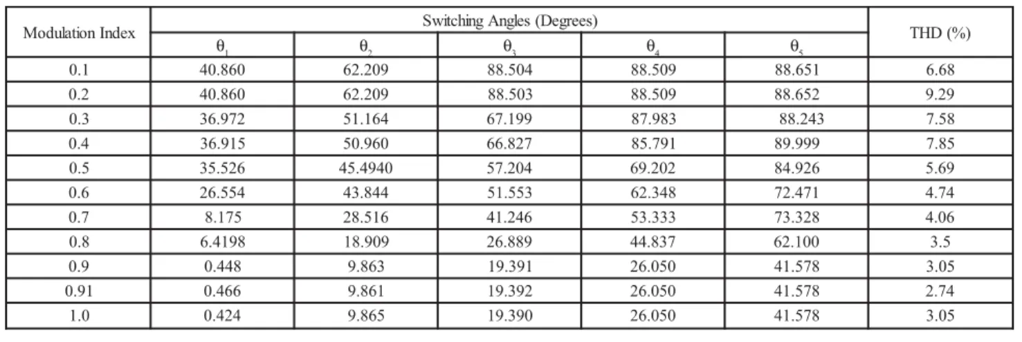
THD Minimization from H-Bridge Cascaded Multilevel Inverter Using Particle Swarm Optimization Technique
Texto
Imagem


Documentos relacionados
These results highlight important elements in patients’ initial steps toward seeking medical mar- ijuana and key insights into the need to drive the incorporation of medical mar-
This study is aimed identifying students’ perception of open and distance education system -being the educational technology of the twenty first century-, the present
The level of the estimated number of births obtained from the ASFRs derived using the traditional Brass technique is always higher than that obtained when using data from SINASC
18 shows the total output voltage waveform of 5 level cascaded h-bridge multilevel inverter using amplitude modulation (AM) technique. Fourier analysis of output
In this paper, a hybridised single-phase cascaded multilevel inverter topology using reduced number of power switches is proposed.. The power circuit configuration
CASE STUDY OF M.PHIL SECONDARY TEACHER EDUCATION PROGRAM OF ALLAMA IQBAL OPEN UNIVERSITY is the title of this article. This study focuses to explore up to
Performance evaluation of the proposed BLDC drive is carried out under varying input AC voltage at rated load (i.e. rated torque and rated speed) to demonstrate the
his cost-minimization analysis using real data from clinical prac- tice found that in the Brazilian context, from the perspectives of the public healthcare system and of society,
