Transformer less based modified cascaded
seven levels H- bridge inverter control of
DSTATCOM
1Ganesh Prasad Reddy,
1
Department of Electrical and Electronics Engineering, Vasireddy Venkatadri Institute of Technology, Nambur (V), Pedakakani (M), Guntur (Dt), India
2
K. Ramesh Reddy
2
Department of Electrical and Electronics Engineering, G. Narayanamma Institute of Technology, Hyderabad, India
Abstract—This paper studies an investigation of Transformer less Based Modified Cascaded Seven-Level (TBMCSL) H – bridge Inverter is used in a Distribution Static Compensator (DSTATCOM) in Power System (PS), making use of TBMCSL advantages of low harmonics distortion, reduced number of switches and suppressed switching losses. In order to improve the power factor, compensate the reactive power and eliminate the Total Harmonics Distortion (THD) drawn from a Non-Liner Diode Rectifier Load (NLDRL) of DSTATCOM, we propose a Sub-Harmonics Pulse Width Modulation (SHPWM) technique is used as control for the switches of TBHSL H – bridge Inverter. The D-Q reference frame theory is used to generate the reference compensating currents for DSTATCOM and Proportional and Integral (PI) control is used for capacitors dc voltage regulation for DSTATCOM. A TBMCSL H – bridge Inverter is considered for shunt compensation of a 9 kV distribution system. The results are verified through MatLab/Simulink software package.
Keywords— DSTATCOM, Sub-harmonic pulse width modulation, Proportional-Integral control, D-Q reference frame theory.
1. Introduction
Shunt compensation for medium voltage distribution systems requires higher rating for voltage source converters (VSCs). Ratings of the semiconductor devices in a VSC are always limited; therefore for higher rated converters it is desirable to distribute the stress among the number of devices using multilevel topology [1]. Cascaded multilevel configuration of inverter has the advantage of its simplicity and modularity over the configurations of diode-clamped and flying capacitor multilevel inverters. Application of cascaded multilevel converters for shunt compensation of distribution systems has been described in [2]-[3].
The multilevel power conversion has been receiving increasing attention in the past few years for high power application [4]. Numerous topologies have been introduced and studied extensively for utility and drive applications in the recent literature. These converters are suitable in high voltage and high power applications due to their ability to synthesize waveforms with better harmonic spectrum and attain higher voltage with a limited maximum device rating [1], [4]. There are various current control methods for two-level converters [5]. Hysteresis control of power converters, based on instantaneous current errors, is widely used for the compensation of the distribution system as it has good dynamic characteristics and robustness against parameter variations and load non-linearties [6].
A distribution static compensator (DSTATCOM) is a voltage source converter (VSC) based device. When operated in a current control mode, it can improve the quality of power by mitigating poor load power factor, eliminating harmonic content of load and balancing source currents for unbalanced loads [6]-[7].
Therefore in this paper TBMCSL H – bridge Inverter based DSTATCOM control in PS is proposed. A SHPWM technique is used as control for DSTATCOM. The TBMCSL H – bridge Inverter topology based DSTATCOM balances the source currents and reduces THD while improving the load power factor. The simulation of DSTATCOM with its control model is implemented in MatLab/Simulink.
In section 2, we will present the operation of TBMCSL H – bridge Inverter. The control of DSTATCOM is presented in section 3. A SHPWM technique is well executed in section 4. Simulation results of system are discussed in section 5. The conclusions and future work of system is discussed in section 6.
2. Operation of Modified Cascaded Seven levels H-Bridge Inverter
found to be limited [8]. With a modular H- bridge topology [8], realization of multilevel inverters using a hybrid approach involving IGBTs and IGCTs operating in synergism is possible.
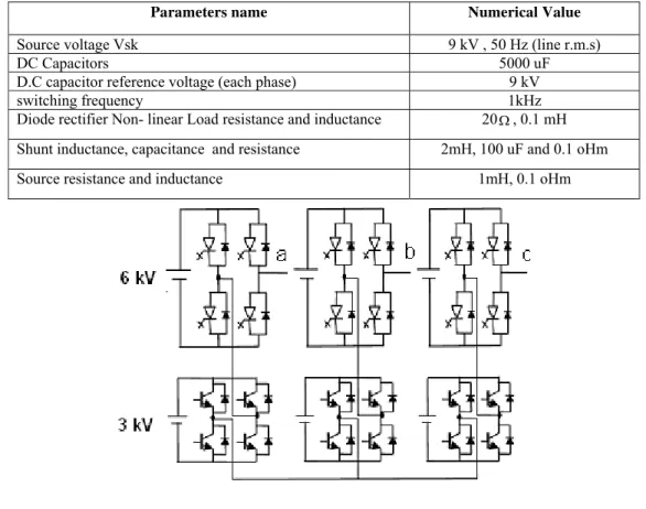
Hybrid multilevel inverter topologies have been studied for high power applications in [9] – [10]. The topology presented in reference [10] combines a Gate Turn-Off (GTO) thyristor based inverter and an IGBT inverter, similar to that shown in Fig. 1. It may be verified that with a combination of 6 kV and 3 kV dc bus voltages in this topology, it is possible to synthesize stepped waveforms with seven voltage levels viz -9 kV, -6 kV, -3 kV, 0, 3 kV, 6 kV, 9 kV at the each phase leg output. As shown in Fig. 1, the higher voltage levels (± 6kV) are synthesized using GTO inverters while lower voltage levels (± 3kV) are synthesized using IGBT inverters. But it is well known that switching capability of GTO thyristors is limited at high frequencies [9]. Hence a hybrid modulation strategy which incorporates stepped synthesis in conjunction with variable pulse width of the consecutive steps is proposed. The switching state of the inverters between phase “ab” for various levels of command signal is listed in Table 1. Similarly, in remaining phases between “bc” and “ac” except the phase difference.
3. Dstatcom Control
Fig. 2 shows a three-phase four-wire distribution system that is compensated by a DSTATCOM in PS. The three-phase load is supplied from the voltage source Vskthrough the feeder with the impedance of (Rsk, Lsk),
where k= a, b, cfor the three-phase respectively. The DSTATCOM is represented by VSCs in the shunt path with the interfacing inductance Lshk. The resistance Rshk represents the loss equivalent due to the inverter
switching. The voltage at the Point of Common Coupling (PCC) is denoted by Vtk. The currents flowing through
the different branches at the PCC are the source current Isk, the load current ilk and the current injected in shunt
branch Iskk.
3.1 Reference Currents Generation
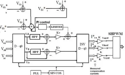
There are several methods to extract the harmonic components from the detected three-phase waveforms [7]. Among them, the so-called p - q theory based on time domain has been widely applied to the harmonic extraction circuit of active filters. The detected three-phase voltage is transformed into the D – Q coordinates as shown in Fig. 3. The second order digital high pass filters (HPFs) with the same cut off frequency as 10Hz extract the dc component Vhd*, Vhq* and V0 which corresponds to the fundamental frequency in the coordinates.
In line – voltage regulation part is performed by a feedback control. Two co – ordinates Vd and Vq is
compared with harmonic extracted voltage Vhd *
and Vhq *
. A gain KV amplifies and to produce current references
for harmonic damping Ihd, Ihq, and I0 as shown in equation (1) , equation (2) and equation (3). The current
reference for the voltage – source inverter is the sum of the current references from the three parts, as follows:
I*cd (s) = Kv (Gh Vhd *
- Vd) + (Vdc* - V dc) (1)
I*cq (s) = Kv (Gh Vhq* - Vq) (2)
I* 0 (s) = 1/3 (Vsa + Vsb + Vsc) (3)
The obtained current reference is converted to three phase current reference by inverse D–Q transformation I*ca, I
* cb, andI
*
cc. The three-three phase reference compensating current is compared with the DSTATCOM
compensating current extracted from ac system. Thus three phase compensating current I ca, I cb, andI cc are
produced.
Each phase of the compensating currents is amplified by a gain K in order to produce the three AC voltage references of the feedback loop, given by:
Varef =K* (I*ca -I mca ) (4)
Vbref =K* (I*cb -I mcb) (5)
Vcref =K* (I *
cc -I mcc) (6)
Finally, each voltage reference of the DSTATCOM is compared with a multicarrier triangular waveform (1000 Hz) to generate the switching patterns for the TBHSL H – bridge Inverter.
3.2. DC Bus Voltage Control
A DC bus controller is required to regulate the DC bus voltage Vdc and to compensate the inverter losses in
Fig. 3. The measured DC bus voltage Vdc of each phase is compared with its reference value Vdc*. Similarly,
3.3. Sub-Harmonics Pulse Width Modulation (SHPWM) technique
Conventional SHPWM technique for multilevel inverters employ extension of carrier based techniques for two level inverters. It has been reported that the spectral performance of a five level waveforms can be significantly improved by employing alternative dispositions and phase shift in the carrier signals [12]-[13]. This paper extends this concept to a seven level case where the available options for polarity and phase variation. The carrier polarity variation is implemented control for DSTATCOM in this paper. It is based on a comparative evaluation of possible dispositions of triangular carrier waveforms depending on their relative polarities. For an m-level inverter this technique requires m-1, which are compared to a reference sine wave. Thus, for a seven-level inverter the number of carrier signals is six and there exists five possible carrier signal configurations. The carriers are named +1V, +0.66V, +0.33V,-0.33,-0.66Vand -1V after their dc position as shown in Fig.5. Their phase position is + for a carrier in phase and – for a carrier 180 degree out of phase. 4. Simulation Results Discussion
The main purpose of this section is studies the simulation results of DSTATCOM in PS. Simulations have been performed on the DSTATCOM in PS with parameters listed in Table 2.
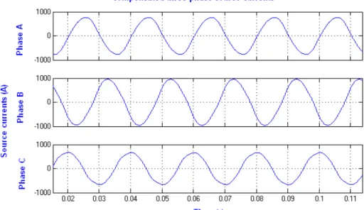
Fig. 5 shows generation of reference and carriers signal for SHPWM technique, which is used to control the switches of TBMCSL H- bridges inverter. The THD in the source current for uncompensated system is 15.5%. The three-phase currents are unbalanced with the poor power factor. Fig. 4 shows the source currents for the uncompensated system. It is desired to bring down the THD in source current to be within an acceptable limit with good tracking of fundamental component, while balancing the three-phase source currents.
Fig. 6 shows the compensated source currents using the proposed modulation and control technique. The source currents are balanced with the THD improved to 4.23% as shown in Fig. 7.
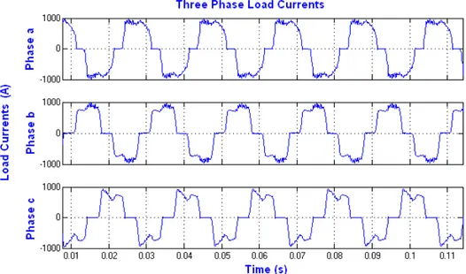
Fig. 8 shows the load currents for the compensated system. It can be observed that has an acceptable limit. The shunt current tracking characteristic is shown in Fig. 9. In an error of about 05 A (rms) is observed in the tracking of the fundamental component.
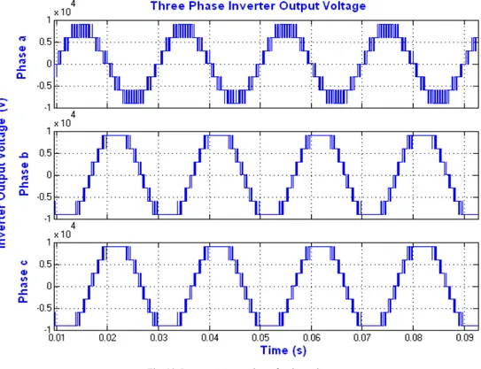
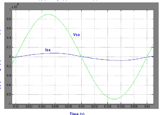
The 7-level inverter output voltage for the phases-a, b and c is shown in Fig. 10. Fig. 11 show for the a-phase. An average switching frequency of 1000 Hz is observed for all the switches. The source current is in phase with the terminal source voltage as shown in the Fig. 12 (for phase-a only). This implies a near unity power factor operation.
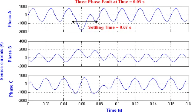
Fig. 13 shows the convergence of the dc-link voltage of the cascaded TBMCSL H – bridges Inverter for the phase-a. It can be found that the dc voltage has small ripple with designed PI control. Fig. 14 three phase source currents with DSTATCOM for the three-phase fault. It cane be found that the settling time of 0.02 s, which proves that the transient stability performance of the proposed system.
5. Conclusions
This paper investigated a TBMCSL H – bridge Inverter is used in a DSTATCOM in PS has been successfully demonstrated in MatLab/Simulink. The benefits of TBMCSL H – bridge Inverter has low harmonics distortion, reduced number of switches to achieve the seven- level inverter output over the cascaded seven level inverter and reduced switching losses.
The TBMCSL H – bridge Inverter for installation on a power distribution system, with focus on harmonic reduction and voltage regulation performances. Harmonics present in the distribution system is significantly reduced by TBMCSL H – bridge Inverter. The results were showed good dc bus voltage – regulation, reduced source harmonic currents and have stable operation. The further work focuses on the study of fuzzy logic control for DSTATCOM
.
Table-1: Switching State Between a and b. Command Signal (Desired Output) GTO Inverter IGBT Inverter Between -09 and -6.0 kV -6.0 kV 0
-3.0 kV Between -6 and -3.0 kV -6.0 kV 0
+3.0 kV Between -3.5 and -0.0 kV 0.0 kV 0
-3.0 kVBetween 0.0 and 3.0 kV 0.0 kV 0
+3.0 kVBetween 3.0 and 6.0 kV +6.0 kV 0
-3.0 kVTable-2: Parameters of DSTATCOM in PS
Parameters name Numerical Value
Source voltage Vsk 9 kV , 50 Hz (line r.m.s)
DC Capacitors 5000 uF
D.C capacitor reference voltage (each phase) 9 kV
switching frequency 1kHz
Diode rectifier Non- linear Load resistance and inductance 20, 0.1 mH Shunt inductance, capacitance and resistance 2mH, 100 uF and 0.1 oHm
Source resistance and inductance 1mH, 0.1 oHm
Fig. 1. Simplified schematic of the Modified Cascaded Seven Level H- Bridge Inverter
Fig.3. Block diagram of the control circuit equipped with the function of voltage regulation and harmonic reduction for DSTATCOM.
Fig.4.Three phase source currents for uncompensated DSTATCOM in PS
Fig. 6.Three phase source currents for compensated DSTATCOM in PS
Fig. 8. Three phase load currents for compensated DSTATCOM in PS
Fig. 10. Inverter output voltage for three phases
Fig. 12 In-phase source current with terminal voltage for phase-a
Fig. 14. Three phase source currents for compensated DSTATCOM in PS at three phase faults.
References
[1] J. S Lai and F. Z. Peng, “Multilevel converters-A new breed of power converters,” IEEE Trans. Industry Applications, vol.32, no.3, pp. 509-
[2] F. Z. Peng., J. W. McKeever and, D .J. Adams, “A power line conditioner using cascade multilevel inverters for distribution system,” IEEE Trans. Industry Applications, vol.34, no.6, pp. 1293-1298, Nov.-Dec.1998.
[3] W. Liqiao, L. Ping, L. Jianlin and Z. Zhongchao, “Study on shunt active power filter based on cascaded multilevel converters,” 35th
IEEE Power Electr. Spec. Conf. (APEC), vol.5, pp. 3512-3516, 20-25 June 2004.
[4] B.S.Suh, G. Sinha, M.D. Manjrekar, T.A. Lipo,”Mulilevel Power Conversion- An Overview of Topologies and Modulation Strategies,” OPTM’98 Conference Proceedings, pp. AD-11-AD-24, 1998.
[5] M. P. Kazmierkowski and L. Malesani, “Current control techniques for three-phase voltage-source PWM converters: A survey,” IEEE Trans.Industrial Electronics, vol.45, no.5, pp. 691-703, Oct. 1998.
[6] A. Ghosh and G. Ledwich, Power Quality Enhancement using Custom Power Devices, Kluwer Academic Publisher, Boston, MA, 2002.
[7] A. Ghosh and G. Ledwich, “Load Compensating DSTATCOM in weak AC systems,” IEEE Trans. Power Delivery, vol. 18, No. 4, pp. 1302-1309, Oct. 2003.
[8] P. K. Steimer, H.E. Gruning, J. Wuninger, E. Caroll, S.Klaka, S. Linder,”A New Emerging Technology for High Power, Low Cost Inverters,”IEEE-IAS’98 Conference Proceedings, pp.1592-1599, 1998.
[9] H. Gruning,”Power Electronics Circuit Arrangement having Plural Power Converters”, U.S. Patent No. 5,805,487, 1998.
[10] M.D. Manjrekar, T.A. Lipo,”A Hybrid Mulilevel Inverters Topology for Drive Applications,” IEEE-APEC’98 Confernce Proceedings, pp. 523-529, 1998.
[11] D. N. Zmood and D. G. Holmes, “Stationary frame current regulation of PWM inverters with zero steady-state error,” IEEE Trans. Power. Electr., vol.18, no.3, pp. 814-822, May 2003
[12] G. Carrara, S. Gardelta, M. Marchesoni,”A new multilevel PWM method: theoretical analysis”, IEEE Trans. On power electronics Vol. 7. No. 3 , July, pp.497-505, 1992.