Elisabeta Spunei, Ion Piroi, Florina Piroi
Basic Concepts in the Diagnosis of Traffic Safety
In-stallations Using Fuzzy Logic Based Models
The diagnosis of failures in train traffic installations can be done in sev-eral ways: direct observations and measurements, software assisted diagnosis using specific software packages, process variable monitoring for electronically centralized installations. This work presents basic con-cepts for Model Based Diagnosis (MBD) that uses fuzzy logic to analyse the integrity of Centralized Traffic Control Installations (CTC) in train traffic. We define the diagnosis relations to be used and show how to apply them to train traffic security installations. Implementing these concepts into an expert system assists maintenance operators in quick failure diagnosis of the train traffic security installations.
Keywords: (CTC), Model Based Diagnosis, logic relations, fuzzy logic
1. Introduction
Railroad Centralized Traffic Control installations are very complex systems that command and control train traffic, being essential in train traffic security. Train stations where the CTC installation is electro-dynamically realised (ED-CTC) have more complex subsystems, each of them, again, having subcomponents that inter-act with each other. Each subsystem interinter-acts with other subsystems, therefore the safety of the traffic passing an ED-CTC station is ensured when all subsystems function within normal parameter values.
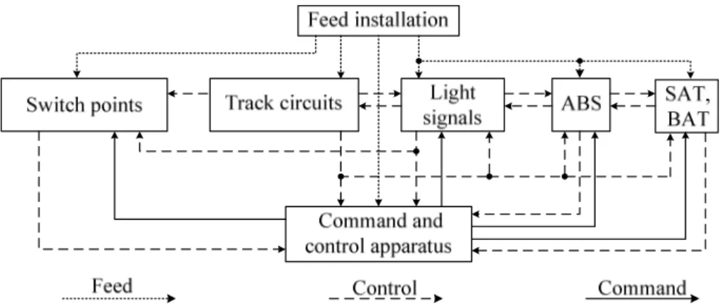
Fig. 1 shows the interconnection block schema for a railway station with CTC and ABS (Automatic Block Signalling) installations.
All subsystems are controlled through the command console, any failure of the one or more subsystem causing an irregular behaviour of the whole system, behaviour which is usually signalled. Diagnosing the system or the subsystem is necessary in order to detect the failing component(s) that are the cause of the faulty behaviour.
Currently, for these types of installations, the failure diagnosis is done by di-rect observations of the various signals and measurements of equipment states.
The diagnosis time strongly depends on the maintenance staff’s detailed knowl-edge on the whole system and subsystems internals.
Figure 1. Subsystems interconnection block scheme
This work proposes to develop an expert system (ES) that uses fuzzy logic to diagnose CTC stations. ESs are used also in power electric systems [1].
The expert system will receive information from various subsystem compo-nents and will process and compare them with the ES model. The ES output will be a minimal set of causes for the signalled system misbehaviour, corresponding to the signals displayed.
2. Principles of the Model Based Diagnosis
To better understand the basic principles in the model based diagnosis we will use the word system to refer to both systems and subsystems.
To use the model based diagnosis it is necessary to completely describe each system component. This step is called system description, SD [1,2]. Logical rela-tions that describe how the components work, the links between components, and the workings of the whole system are established. These relations are, in fact, propositional logic sentences that form the system’s propositional logic, SPL.
A logical consequence of the detailed and correct system description is the correct operation of the system. Any discrepancy between the system’s punctual behaviour (pointwise) and its description is caused by a faulty component. Thus the system description is based on the logical propositions that describe the com-ponents, their operation and the links between them.
CC
⊃
CD
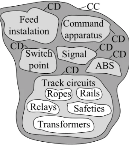
(1) An example of a defect, in our case, is the fact that an entry signal cannot be commanded on the ‘free’ position. The concurrent components of this symptom are: damaged track circuit, damaged track point, faulty power feed installation, line occupied by rolling stock, previously executed movement on the same line, damaged command apparatus. Based on observations it is noted that the system failure is caused by the track circuit which does not function properly. In this case the main candidate components are: safeties, transformers, IMVS, BDF, TR relays, the track relay, the filter, the railway tracks, connections, ropes (Fig. 2).Switch
point
Signal
ABS
Feed
instalation
Command
apparatus
Track circuits
Transformers
Safeties
Ropes Rails
Relays
CD
CD
CD
CD
CD
CD
CC
Figure 2. Concurrent and candidate components
In our example, then, we have:
{
}
{
}
int,
,
,...
,
,
,...,
CC
Switch po
Signal ABS
Track circuit
CD
Transformers Safeties Rail track
relay IMVS
=
=
(2)The faults in the track circuit operations are caused by the breakdown of one or more candidate components in the CD set.
We continue with some further basic definitions and relations in the model based diagnosis systems.
The CD’s operation state is described by a predicate, AB, which indicates the abnormal operation (faulty state). The normal operation state is given by ¬AB [2].
Definition 1: System description
FS
⊃
SD
∪
CD
(3) where:- CD is a finite candidate system components set;
- SD is a finite subset of system’s propositional logic, SPL. The system diagnosis, ∆, is applied when the following holds:
SD
∪
CD
≠
FS
(4)Using the AB predicate we can describe the components’ functional proper-ties. Suppose we want to express the following sentence: “Normally, the NF1-800 operating voltage is between 8 V and 12 V” [3]. Then, the corresponding relation is:
( )
(
)
( )
(
)
(
)
1 800
,
8
14
NF
CD
voltage CD u
AB u
rate u
rate u
−
∧
∧
¬
⊃
≥ ∧
≤
(5)With the same predicate we can describe the possible effects of the compo-nents with the relation:
type CD
( )
∧
AB CD
( )
⊃
fault CD
1( )
∨
fault CD
2( )
∨ ∨
...
fault CD
n( )
(6)where type can be: relays, safeties, transformers, etc. Definition 2: Observing the system
Observing the system, OBS, is a finite set of first order logic sentences that are used to diagnose the system. Therefore, the functional system can be de-scribed by the relation:
FS
⊃
SD
∪
CD
∪
OBS
(7)These observations belong to the system’s propositional logic and their role is to signal the system’s faulty behaviour.
Definition 3: System diagnosis
The system diagnosis is a minimal set
∆ ⊆
CD
, such that:
SD
∪
OBS
∪
{
AB c c
( )
∈ ∆ ∪ ¬
}
{
AB c c
( )
∈
CD
− ∆ ∃
}
(8)The diagnosis aims to discover the faulty component that causes the whole system to misbehave. The conditions to apply the diagnosis are:
(
SD
OBS
)
∃
∪
(9)b)
{ }
is a diagnosis for the (SD, CD, OBS) system if:
SD
∪
OBS
∪ ¬
{
AB c c
( )
∈
CD
}
∃
(10) c)∆ =
{
AB c
( )
i}
is a diagnosis for the (SD, CD, OBS) system if:
SD
∪
OBS
∪ ¬
{
AB c c
( )
∈
CD
− ∆ =
}
AB c
( )
i (11) d)∆ ⊆
CD
is a diagnosis for the (SD, CD, OBS) system if ∆ is a minimal setsuch that:
SD
∪
OBS
∪ ¬
{
AB c c
( )
∈
CD
− ∆ ∃
}
(12) Definition 4: System’s conflictsA set of conflicts of the (SD, CD, OBS) system is a set
F
=
{
c c
1,
2,...,
c
n}
, withF
⊆
CD
, such that:( )
( )
( )
{
1,
1,...,
1}
SD
∪
OBS
∪ ¬
AB c
¬
AB c
¬
AB c
does not exist (13)Relation (12) can be redefined using the conflict set terms:
CD
∆ ⊆
is a diagnosis for the (SD, CD, OBS) system if ∆ is a minimal set such thatCD
− ∆
is not a conflict set for (SD, CD, OBS).Definition 5: The goal set:
Let C be a collection of sets. A goal set for C is a set
H
⊆
∪
S C∈S
, such that{ }
H
∩ ≠ ∅
S
for anyS
∈
C
. O goal set for C is minimal if none of its subsets is a goal set for C.To compute the diagnosis set we give the following: Theorem 1:
CD
∆ ⊆
is a diagnosis for system (SD, CD, OBS) if ∆ is a minimal goal set for the conflict set collection of the (SD, CD, OBS) system.3. The Expert System to Diagnose the CTC Installations using the Model Based Diagnosis Method
CTC Installation
Measure convertor
Inference Engine
Knowledge Base
Database of system elements Expert System
User Interface
Figure 3. The SE interconnection block schema
This diagram contain:
- The CTC installation that is to be monitored at various points and diag-nosed;
- The Expert System that loads into the knowledge base the set of rules for the normal operation state of the installation. The knowledge base is loaded from the database of system elements. These rules are processed by the inference engine that uses fuzzy logic operators [6].
- The user interface where the conflict sets are displayed.
In this work we show an expert system designed to diagnose a CTC type CR4 installation, on a track section with ABS installations.
Fig. 4 shows the diagram of a railway station with 2 traffic lines.
Figure 4. Railway station diagram for which an expert system is proposed
In this figure we identify the following installations:
- Switch points (no. 1 and no. 2), which allow the train passage from one line to the other;
- Track circuits (023 C, 024 C, 1C, II C) and isolated sections (1 Si, 2 Si)
- Light signals (X, X 1, X II, Y, Y 1, Y II) which signal whether the train en-try/exit into/out of the railway station is allowed;
- The central post, PC, where the command and control panel is located, as well as the relay room. The command and control apparatus and com-mands the train traffic and monitors the installation’s conflictual state; - The ABS installation at the X and Y station ends. This installation
com-mands the traffic reversion [7]. This installation contains light signals and track circuits with specific characteristics.
According to this scheme we created the block diagram for the installations that deliver state information to the expert system (Fig. 5).
Centralized Traffic Control Installations
Point 1 Point 2 Signal X Signal Y Signal X 1 Signal X II Signal Y 1 Signal Y II
Switch Point Signals
023 C 024 C 1 C II C 1 Si 2 Si
Track circuits
X 1AD X 2AD X D
X OL X KL
X ABS
Y 1AD Y 2AD Y D
Y OL Y KL
Y ABS
SR A 1 A 2
S 1 S 2
Power feed
AM
AA AR
Figure 5. Installation block schema monitored by the proposed Expert System
The DS system description contains: - The system’s topology;
- Locations of the measurement sensors for each mentioned installation; - Nominal operation parameters for the main installation components; - Limit parameter values for the operation of the main components in all
the mentioned installations;
- The fuzzy rules used to determine the fuzzy indicators.
The CD set, described by
¬
AB c
( )
contains sentences of the form:- The correct operation of the switch point (Mac)i is controlled by the point control relays (KM) states, by the point position plus and minus control relays (KMP, KMM) states, where i = 1, …, M and M is the number of point control relays in the station;
the fire relay FRA2G (fire red, white, yellow 2); where j = 1, …, S and S is the number of fire relays in the station;
- The correct operation of the (CDC)k track circuits is controlled by the C track relays and Si isolated section relays, where k = 1, …, CC where CC is the
number of circuit control and section control relays in the station;
- The correct operation of the (ABS)l is controlled by the OL (occupied line) relay, KL (control line) relay, D (direction control) relay, where l = 1, …, L and L is the number of ABS installations neighbouring the CTC station;
- The correct operation of the power feed installation (ALIM) is controlled by voltage monitoring relays: AM (switch point failure), AA (d.c. power feed), SR (rectifier monitor), etc., where k = 1, …, AL where AL is the number of voltage monitoring relays in the station.
The union operator,
SD
∪
CD
, gives the following sentences: - The operation of all switch points is correct;- The operation of all track circuits and section circuits is correct - The operation of all signals is correct;
- The operation of all ABS installations is correct; - The electric power feed installation is correct;
The OBS observations set contains sentences of the following form: - The switch point is positioned A;
- The point states is A; - The track circuits state is A; - The signals state is A;
- The ABS installation state is A;
- The electric power feed installation state is A, where
{
,
,
,
}
A
∈
optim favorable admissible inadmissible
(14)The diagnosis solution using the MBD system is the goal set ∆ that contains subsets of the CD set defined like:
- The KMP voltage value is not optimal; - The FRAG2 relay state is inadmissible, etc.
4. Conclusion
In this work we presented the basic concepts needed to apply the model based diagnosis with an example of concept instantiation for CTC installations. We proposed an expert system applicable to a train station with two traffic lines.
The authors’ contributions are:
- Identifying the elements that need to be monitored and establishing how they should be controlled;
- Shortly describing the components that are part of the CD set; - Shortly describing the DS system and the corresponding operations; - Establishing a minimal set of observations.
As future work we plan to further develop and implement this model for the respective installations.
References
[1] Luştrea B., Borlea I., Application of model based diagnosis for steady state power systems operation. Theory and basic concepts. Proceedings of the Fifth International Power Conference, Timişoara, 2003.
[2] Reiter R., A theory of diagnosis from first principles. Journal Artificial Inteligence, Volume 32, Issue 1, 1987, 57 – 95.
[3] Stan A.I., David S., Electrodynamic centralization and automatic line block, vol 1, E.D.P București 1983.
[4] Elasaadawi A.M., a.o., Development of an Expert System to fault diag-nosis of three phase induction motor drive system. Power System Confer-ence, 2008. MEPCON 2008. 12th International Middle-East.
[5] Angeli C., Diagnostic Expert Systems: From Expert's Knowledge to Real-Time Systems. TMRF e-Book Advanced Knowledge Based Systems: Model, Applications & Research (Eds. Sajja & Akerkar), Vol. 1, pp 50 – 73, 2010.
[6] Voloşencu C., Fuzzy systems and neural. Publishing house Polytech-nica, Timişoara 2007.
[7] Spunei E., a.o., Diagnosis Charts for Regular Inversion Failures of an Automatic Block Signal Installation, International Conference on Applied and Theoretical Electricity ICATE, 23-25 October 2014, Craiova.
Addresses:
• Lect. Dr. Eng. Elisabeta Spunei, “Eftimie Murgu” University of Reşiţa, Piaţa Traian Vuia, no. 1-4, 320085, Reşiţa, [email protected]
• Prof. Dr. Eng. Ec. Ion Piroi, “Eftimie Murgu” University of Reşiţa, Piaţa Traian Vuia, no. 1-4, 320085, Reşiţa, [email protected]