Abstract— Product Design is a process of creating new product by an organization or business entity for its customer. Being part of a stage in a product life cycle, it is very important that the highest levels of effort are being put in the stage. If not done properly, the product will create problems in the future which in the end, come back to the company which designed the product and the after effect might be catastrophic. This paper demonstrates how Six Sigma Methodology is used in Product Design. Six Sigma utilizes quality tools in the design process in order to avoid future problems in the product. Each phase of the Design for Six Sigma (DFSS) will have a unique tool that can be used for Product Design. The Product Design of an outdoor Wireless Access Point device named WIWI-1.8® will be used as a subject of reference in this paper.
Index Terms—Six Sigma, Product Design, DFMEA, DFSS.
I. INTRODUCTION
S
ix Sigma approach in Product Design or better known as Design for Six Sigma (DFSS) consist of five phases that a Design Engineer has to follow. They are Define, Measure, Analyse, Design and Verify (DMADV). In each of these phases there are tools that will help to ensure that the Product Design is properly done. These tool will ensure that the Product will meet customer requirement (Six Sigma takes the needs of the customer as inputs in the Define phase) thus will give the customer higher satisfaction when using the product. Six Sigma can be defined in formulation asY= f(x)
Where Y is the quantitative representations of Customer Requirement and f(x) are inputs that contribute to the outcome of Y.
II. THE PHASES
A. Define
The Product Design cycle starts with the product definition cycle or Define phase. In Define phase is where we identify the business opportunity. When an opportunity has been identified, which is usually will relates to the growth of the company, a team will be formed to work on
Manuscript received Feb 01, 2013
Sheikh M.Shahrizal Mohd Rafique is a Staff Engineer with MIMOS Berhad, Malaysia ( phone: +603-8995-5000 ; fax: +603-8991-4243 ; e-mail: shahrizal.rafique@ mimos.my).
this opportunity thus bringing us to the first tool of the Six Sigma Methodology which is the Team Charter.
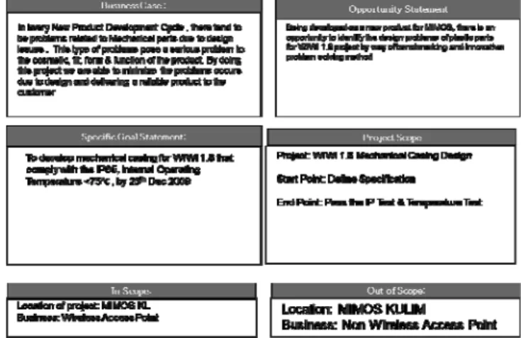
Team Charter is a document that summarizes the project in a single page. It shows the direction of the team and serves as a contract between the stakeholders and team members.
There a few elements that is compulsory in developing a Team Charter, among them:
• Business Case: Describes the benefit for undertaking the project,
• Opportunity Statement: The “why” of undertaking the project
• Goal Statement: Describes the objective of the project in measureable terms.
• Project Scope: Defines the boundaries of the project • Project Plan: Define the major milestones & timing & • Team Selection: Team members & responsibilities.
Fig. 1.Team Charter for the WIWI 1.8® Project ©MIMOS Berhad 2012
Fig. 2. Team Charter (Members & Responsibility) ©MIMOS Berhad 2012
The Use of Design for Six Sigma (DFSS)
Methodology in Product Design
Fig 1 & Fig 2 shows an example of Team Charter and the information contains in it. Among the important information that it show is the Goal Statement, in this case is “To Develop mechanical casing for WIWI 1.8 that comply with the IEC IP65 Standards, Internal Operating Temperature < 75°C by ¹25th Dec 2009”. We can see here that the objective of the project, the major specification and the timeline is stated clearly.
The next step in the Define Phase of the Six Sigma Product process is Defining the Customer Requirements. The objective of this step is to identify internal/external customer wants/needs or commonly known as Voice of Customers (VOC) which can be translated into quantifiable requirements. Here is where what the customer wants & what their needs are. From here we can design a product based on these inputs and deliver it according to the customer expectations.
The Six Sigma tools used here are KJ Analysis or also referred as the Affinity Diagram. It is named after its inventor Kawakita Jiro. KJ Analysis allows the team to quickly reach a consensus on priorities of subjective and qualitative data.
In the example, VOCs are based on a question “What do you want for WIWI 1.8 design?”
Fig. 3. VOCs being grouped ©MIMOS Berhad 2012
VOCs are group into several group (Fig 3), team will then vote for the group that has a higher priority. All the features will then be identified whether they are NEW, UNIQUE, STANDARD or DIFFICULT. The features from these groups will then be transferred to another tool of Six Sigma, which is Quality Functional Deployment.
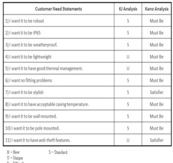
KJ Analysis is always paired with Kano Analysis, Kano analysis categorised Customer Requirement into four categories:
Delighters: The absence of a delighter has little or no negative impact, while introducing the delighter generates excitement and satisfaction
Primary Satisfiers: More of a Satisfier leads to more customer satisfaction, in generally linear
relationship
Indifferent: Refers to aspect that are neither good nor bad and no real impact on customer satisfaction.
Must-Be’s: Necessary for a product to be seriously
expectation but higher standards of Must-Be’s have little impact on satisfaction.
Fig. 4. Kano Satisfaction Model
Fig. 4 shows the Kano Satisfaction Model, consist of an (x, y) graph, where the x-axis represents how good the Product is in achieving customer requirement. The y-axis of the Kano model records the customer satisfaction level. Based on the above steps the features will be categorised into their respective group.
Fig. 5. Product Features Tabled Using Kano Analysis ©MIMOS Berhad 2012
B. Measure
The 2nd phase of using Six Sigma Methodology in Product design is the Measure phase. Here is where we translate the VOCs into measurable Critical Customer Requirement (CCR). We will then able to identify the key design factors and critical parameters that we have to satisfy.
Fig. 6 QFD Matrix a.k.a. House of Quality
Fig. 3 shows how the VOCs are transferred to the QFD Matrix (on the left side of the matrix). From here the Technical Requirement are identified. For example, the first VOC that wants the Product to be ROBUST can be translated into several Technical Specs such as Type of Material (Casing) & Material Strength. All features will be given scores against the Technical Requirement. Scores will then be totaled and the highest Technical Requirement can be determined.
QFD helps Design Engineers to reduce development time; a large portion of project development is invested on redoing the same activity several times and/or fixing mistakes. QFD will create a better communication among different functions of the company, people from marketing, operation and other department work together with designers in creating the QFD Matrix. All the features that have been prioritised in the QFD are arranged into a graph form called Pareto Chart.
From example of WIWI1.8 Design here, we can see that among the most important specification that needs to be look into is the Surface Area of the Heat Spreader (device cooling system), Thermal conductivity and Ventilation holes opening area. These parameters have been identified as crucial in the Product Design. Design Engineers should pay more attention to these parameters.
C. Analyse
Analyse here does not mean we analyse the product that have been designed. It is more towards of analysing how the design should be and identify CTQs. CTQs are Critical to Quality metrics used to measure and evaluate the design by. We know that in every Six Sigma based project the objective (Y) is a function of X
Y = f(X1, X2, X3….)
After analysing the Technical Requirement in QFD, we found out that in WIWI 1.8 design there a few item that are Critical To Quality, among them is the Internal Temperature requirement.
Fig. 7 Sub-system Requirement Obtained From QFD
Fig.4 shows how Technical Requirements are translated into CTQs. This process is called CTQ Flow-Down. From here we can see parameters we need to control in our Product Design.
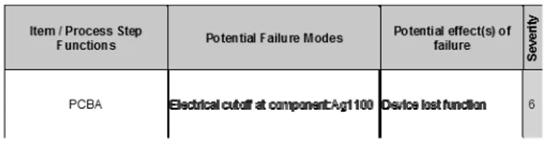
To analyse further on the WIWI 1.8 Design another Six Sigma tool can be used, the Design Failure Mode & Effect Analysis (DFMEA).
It is important to anticipate the potential root cause that any product could have. DFMEA uses RPN numbers as an indicator of the level of seriousness of a potential failure. It is derived from the Severity, Occurrence & Detection level in DFMEA Matrix.
RPN = Severity × Occurrence × Detection
Severity level will indicate the level of impact of that particular failure towards the final customer, may it be “no impact” (lowest severity) or “Hazardous without warning” (highest severity).
Occurrence is the likeliness the failure would happen. Detection is the ability of the controls that have been put in the process to detect the particular failure.
The higher the RPN number the higher the risk of the potential failure. The Recommended Action section will indicate the type of action to be taken to tackle the risk of that particular potential failure thus lowering the RPN.
Outdoor temperature too
high 8 8 384
Introduce cooling
Current Design/Process
Control
Det
ect
io
n
Potential Cause(s)/ Mechanism of failure
Recommende d Actions
RP
N
O
ccu
rr
en
c
e
Fig. 8b : 2nd part of DFMEA ©MIMOS Berhad 2012
In DFMEA, potential failure are analysed from the highest system level to individual part of the product. For the WIWI 1.8 product design example that is shown above, we are looking at the potential failure of the PCB Assembly. Fig. 8a & 8b shows the Potential Failure Mode and the Potential Effect of the failure with the Severity rated at level 6 (Loss of Function). Since this product is used for outdoor, the Potential Cause of failure is the Outdoor temperature and the level of occurrence is set at level 8, meaning that high quantity of product failure is expected from this Failure Mode.
Fig. 8c 3rd Part of DFMEA ©MIMOS Berhad 2012
The RPN number for this failure mode is 384. Comparing this number to the other failure mode in the DFMEA, it is among the highest and actions need to be taken to bring the RPN number down.
Fig. 9c shows the 3rd section of DFMEA, Corrective Actions will be specified here. Once corrective actions are introduced, the Severity level will be improved thus bringing down the RPN number. The use of DFMEA will in a way will anticipate the potential failure that might occur in a product thus at the same time increasing the product quality and reliability.
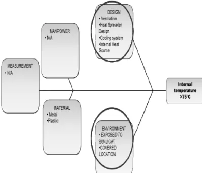
Another Six Sigma tool that is widely used in the Analyse phase of Product Design is the Cause & Effect Diagram also known as The Fishbone d…iagram. This tool will help visually display the potential cause of a problem. Causes in a Cause & Effect are usually categorized into several groups which will help in identifying the root cause of the problems.
The categories mainly are: i. Manpower/ People ii. Methods/Design iii.Materials iv.Machinery v. Environment vi.Measurement
From these generic categories, we can brainstorm possible causes of the observed effect. Fig. 9 below is the sample for the Cause & Effect done for the WIWI 1.8 project? Here, the problem is with the internal temperature of the product where it has exceeded 75°C. We place the problem statement at the head of the Cause & Effect diagrams and create the generic branches to place the respective categories mentioned above.
Fig. 9: Cause & Effect Diagram for High Internal Temperature Issue
After a brainstorming session among the team members, the possible causes are listed in the category boxes. From here the team members can plan the next cause of action.
D. Design
Once the Analyse phase is complete, the next phase in using Six Sigma Methodology in Product Design is the Design phase. The objective of this phase is to implement all items that have been discussed in the Define, Measure & Analyse phase into the detail design.
Fig 10. Industrial Designer’s Data for WIWI 1.8 ©MIMOS Berhad.
In Design stage, the ventilation holes were added to the Back Cover of the WIWI 1.8 product. The question now is “What is the suitable size for the ventilation holes?” In Six Sigma there is a method in determining the optimize value of certain parameters given the factors contributing to the wanted output. The tool or method is called Design of Experiments (DOE). DOE is method for planning, conducting & analysing a test where the input factors involved are changed in order to observe the changes in the output of the system. One of the most known experimental designs is the Factorial Experiments.
Minitab® is the preferred statistical software used to plan this DOE experiment. The features in Minitab® allow engineers to analyse the results of the experiments. In the case of WIWI 1.8 is the optimization. Fig. 11 below shows the planning side of the Minitab® feature where you can determine which type of experiment is suitable for your case and the Run Order Table.
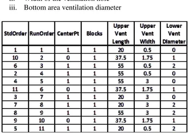
Fig. 11 Factorial Design Planning Table
As for WIWI 1.8, we have 3 Factors:- i. Length of the ventilation hole
ii. Width of the ventilation hole iii. Bottom area ventilation diameter
Fig 12: Experiment Run Order and the parameter settings
Fig 12 above shows the Run Order of the DOE experiments that needs to be done. Depends on the budget allocated & cost involved in the doing these experiments, one can even use simulations tools in doing these experiments. In this case, since the cost of developing the prototype samples for the casing with the different variants of ventilation size is expensive, we have instead used Pro-Engineer® CAD modelling software to generate the samples with the respective variants for the experiments. Combined with Finite Element Analysis software, Abaqus®, we are able to get the results for the Internal Thermal Behaviour of the WIWI 1.8® product.
Fig. 13 Thermal Simulation Using Abaqus®
The result showed (Fig. 13) that the product reached a steady state condition at 74.4°C and the parameter settings for this run are as below:
From this DOE experiment, we are able to finalise the casing design for WIWI 1.8 with the above ventilation holes.
Fig. 14 Updated Casing Design WIWI 1.8
E. Verify
Once the designs have been finalized, the next important phase is the verification stage or as known in the DFSS technique as Verify phase.
Why Verify? Verification is important; verification will tell you that changes done in the Design stage is proven to be working. From the design finalized in the DOE, actual samples with produced by way of prototyping or other methods. These samples will then be subjected to actual temperature test. This will confirm how the design actually performs in actual conditions.
This step is called Confirmation Runs. Doing Confirmation Runs are important whether the designed parameters can be implemented further for mass production parts. At least 3 samples are needed for the Confirmation Runs.
Figure 15 below shows one of the three samples tested during the Confirmation Runs.
Fig. 15 Final Sample Undergoing Environmental Test
The 3 samples were subjected to the environmental test and the result shows that the unit has an average surface temperature of 38°C and an internal temperature of 48°C
Based on the result of the test, the team has decided to proceed with the addition of the ventilation holes on the casing of the WIWI 1.8.This new casing will be used for mass production units.
III. CONCLUSION
Why do we need to do all the steps that have been described in this paper in developing a new product? When an organisation embarks on a certain project, the main objective is to satisfy the customer and in order to do this you have to meet the customer requirements. Design with the Six Sigma methodology (DMADV) is the best way to ensure that your product meets everything that has been specified. It covers all aspect of the design for the product from product definition, critical requirement definition, design optimization and the most important item of all, quality.
With the help of tools such as KJ & Kano Analysis, Quality Functional Deployment, Design of Experiments (DOE), DFMEA and software such as MINITAB®, Pro-Engineer® and Abaqus®, Six Sigma has proven to be a very important part of Product Design. Thus aligning the processes done in DMADV to the Product Development process gates is crucial and shall help the organization develop a good product
REFERENCES
[1] Creveling C.M. , Slutsky J.L. and Antis Dave. Design for Six Sigma in technology and Product Development.
[2] Spool Jared M. The KJ-Technique: A Group Process for Establishing Priorities,2004
[3] Motorola University. Design For Six Sigma: Introduction.