157
Journal of Applied Research and Technology
F
ARADAY PLASMA CURRENT SENSOR WITH COMPENSATION FOR
RECIPROCAL BIREFRINGENCE INDUCED BY MECHANICALPERTURBATIONS
Y. O. Barmenkov & F. Mendoza-Santoyo
Centro de Investigaciones en Óptica, A.C.
Loma del Bosque No. 115 Col. Lomas del Campestre C.P. 37150 León Gto. México
Tel. (52-4) 773-10-17 ext. 204, Fax (52-4) 717-50-06, E-mail: [email protected]
Received: August 15h 2001 and accepted May 3th 2002.
ABSTRACT
A Faraday fiber-optic current sensor was employed to measure the tokamak plasma current. In order to decrease the influence of mechanical perturbations on the sensor sensitivity, a two-pass optical scheme with a variable Faraday mirror at the fiber end is proposed. A decrease, by two orders of magnitude, in the influence of the linear birefringence produced by an external piezoceramic fiber modulator was experimentally observed.
RESUMEN
Se utilizó un sensor de corriente hecho de fibra óptica empleando el efecto Faraday, para medir la corriente en el plasma de un tokamak. Para reducir la influencia de ruido mecánico en la sensitividad del sensor, se propone un arreglo óptico de dos pasos con un espejo variable de Faraday colocado en un extremo de la fibra. Experimentalmente se observo una disminución, de dos ordenes de magnitud, en la influencia de la birefringencia lineal producida externamente por un modulador piezocerámico de fibra.
KEYWORDS: Schlieren, Flow visualization, Natural Convection.
1. INTRODUCTION
Most long-range projections of the global energy foresee a total world energy demand at 2 to 3 times that of the 2000 level. An energy shortfall could occur as early as mid-21st century as the demand for energy overcomes real supply. Fusion energy technologies might help to solve the energy problem, providing an environmentally acceptable alternative to fossil fuel combustion thus ensuring continued economic growth through reliable electricity supply. From this point of view a steady progress in fusion science and technology research strengthens the role of fusion as an alternative energy source for future electricity generating power plants.
Since 1988 scientists and engineers from European Community, Japan, Soviet Union and USA have been working in an unprecedented international collaboration towards the development of fusion - ITER (International Thermonuclear Experimental Reactor based on the tokamak device) [1-3] The Russian Federation undertook the obligations of the partnership of the Soviet Union after its fall in 1991. Other countries, such as Canada and Kazakhstan, have been joined by collaborating with some of the major partners. The project deals with building, for the first time, a test thermonuclear reactor, and thus investigates on the technical components for commercial fusion power plants.
Next Page
In a tokamak, plasma is heated in a toroidal vessel and confined away from the vessel walls by magnetic fields. The plasma current can reach a value of above 10 MA. Precise measurements of the current are very important, since they allow the control of the fusion reaction in the plasma. Evidently, the sensitivity of conventional hard-wire flux change coil (the Rogowski coil) is low under conditions of quasi-direct plasma current and the existence of nuclear radiation near the vessel. From this point of view the fiber-optic Faraday current sensor is preferred due to its very broad frequency band (from DC to dozens of GHz), immunity to nuclear radiation (dedicated optical fibers) and electromagnetic interference, low weight and small size, and simple coupling with fiber-optic data links, among other beneficial characteristics.
Faraday fiber-optic sensors are based on magneto-optic effect (or Faraday effect) in silica fiber. This effect is based on a polarization rotation of light transmitted throughout a magneto-optical medium if a magnetic field is applied longitudinally along the direction of light propagation. All silica-based optical fibers possess this effect. The important advantage of the Faraday sensor is that the Faraday effect is proportional to a magnitude of applied magnetic field, therefore the total rotation of the polarization angle of light is proportional to magnetic field (or electric current) too.
The Faraday current sensor is less sensitive than other current sensors, but it is enough for measuring large magnetic field or electric current, for instance, for plasma current measurements in large tokamaks. The most complicated technical problem is connected with the influence of intrinsic and induced birefringence inherent to single-mode optical fibers, the latter being the sensor sensitive elements. Low birefringence (Lo-Bi) fibers are ideal for Faraday sensors [4]. However they are sensitive to mechanical, thermal, and other external perturbations that give way to a linear birefringence, resulting in signal distortion and a decrease in sensitivity. Several techniques have been proposed [5-7] to compensate for this induced linear birefringence and other type of losses in the fiber sensors. All of them utilize the unique nonreciprocal property of the Faraday effect. The reciprocity-insensitive geometry of the sensors can minimize reciprocal influence in a nonreciprocal effect-based sensor.
In this paper we describe a simple plasma current sensor based on the Faraday effect in Lo-Bi optical fibers, and study the possibility to decrease the reciprocal influence of environment mechanical perturbations. The experiments to measure the plasma current were carried out at the “FT-1” tokamak of the Joffe Physical Technical Institute of St. Petersburg, Russia. To compensate the influence of mechanical perturbations we designed and then experimentally studied a two-pass fiber-optic scheme with a variable Faraday mirror at the fiber end.
159
Journal of Applied Research and Technology
2. BASIC PRINCIPLES OF THE FARADAY CURRENT FIBER SENSOR
A more complete version of the principles for fiber-optic sensors is described in Ref. 8. A magnetic displacement vector B rotates by ϕthe polarization plane of a linearly polarized wave propagating in the
optical medium,
∫
=
Ll
B
d
V
λϕ
, (1)where L is the sensor interaction length and Vλ is the Verdet constant, showing a dependence with
wavelength λ. This formula can be applied to the ideal single-mode fiber with no birefringence. The Verdet constant also depends on the propagation medium properties. The general equation describing this constant may be presented as [9]:
ω ω
ω = ∂∂n
mc q
V 2
2 , (2)
where q is the electron charge, m is the electron mass, c is the vacuum light velocity, n is the medium
refractive index, and ω=2πν=2πc/λ is the light circular frequency (here ν is the light frequency). For a
diamagnetic material it may be approximated as:
(
2 2)
2 02
2 2
3
2
ω ω
ω π
ω
− =
c nm
Nq
V (3)
where N is the molecule concentration, n is the refractive index, and ω0 is the circular fundamental
resonance frequency. Equation 3 shows the dependence of the Verdet constant with the square of the frequency of the light when ν << ν0, where ν0 is in the ultraviolet region for silica glass. Thus, at short
wavelengths the sensitivity of the Faraday sensor is higher than at long ones. For example, for a pure silica fiber the Verdet constant is decreased from 6.11 rad.T-1m-1 for λ = 458 nm to 0.54 rad.T-1m-1 for λ = 1523
nm [10].
For fiber-optic current sensors, in which the sensitive element is presented as the fiber loop, the rotation angle ϕ can be rewritten as
V
d
V
d
V
NI
L L
0
0
µ
µ
ϕ
=
λ∫
B
l
=
λ∫
H
l
=
λ , (4)where H is the magnetic field vector, L is the loop length, N is the number of loops, µ0 is the permeability of
vacuum, and I is the current enclosed by one loop. The total rotation angle is increased with the number of
loops. Nonetheless, the number of loops is sometimes limited due to experimental conditions. There is a possibility to use rare-earth doped optical fibers as the sensor sensitive element, with a higher Verdet constant, however they degrade under the strong radiation near the tokamak.
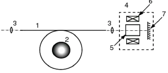
The sensitivity of the Faraday current sensor is thus determined by the rotation angle value, proportional to the measured current, the noise from the light source, and random mechanical perturbations. The main parameter affecting the noise level of the sensor relates to the mechanical perturbations. To decrease the mechanical noise level we used a two-pass optical scheme with the Faraday mirror, a combination of the Faraday cell and mirror, at the fiber end, see figure1. The Jones matrix describing the polarization state of the output beam Eout can be written as,
E
out=
DE
in=
F
−R
−MR
+F
+E
in, (5a)Next Page
=
±± ±± ± 22 21 12 11m
m
m
m
F
, (5b)
τ
α
α
α
α
−
=
±cos
sin
sin
cos
R
, (5c)
=
1
0
0
1
M
, (5d)where Ein is the input beam polarization state (normally linearly polarized light is used), F±, R± and M are
the Jones matrices describing the forward and back propagation of light throughout the fiber, the Faraday rotator and the light reflection from the mirror respectively. mij± are elements of the F± matrices, D = F−R−MR+F+ is the total propagation matrix, α and τ2 are the polarization rotation angle and absorption
coefficient of the Faraday cell. Under absence of non-reciprocal effects (for example, the Faraday effect in the fiber) the elements of the matrices F− and F+ are correlated as (F+)ij = (F−)ji. In such conditions and if α =
(π/4) + δ, where δ << 1, the matrix D can be rewritten as
( ) + + + + + − = 2 22 2 12 22 21 12 11 22 21 12 11 2 21 2 11 2 2 0 1 1 0 det m m m m m m m m m m m m F
D τ δ (6)
It is easy to see that if δ = 0 (i.e. the rotation angle in the Faraday cell is equal to π/4), the nonreciprocal anisotropy is compensated completely. The value of det(F) describes
the fiber optical losses. Thus, using the Faraday mirror allows one to decrease the influence of the mechanical perturbation on the sensor sensitivity.
3. EXPERIMENTAL RESULTS
First, we applied the single-pass optical scheme to check on the possibility to measure the plasma current of the tokamak. The sensor setup is shown in figure 2. The light source, a low-power single-mode He-Ne laser with wavelength λ = 632.8 nm, was mounted in holders that provide the axial rotation for polarization azimuth optimization, according to the fiber linear anisotropy eigen-axes. Single-mode Lo-Bi pure silica fiber, with beat-length about 100 m, was used as a sensor sensitive element. The two fiber turns were arranged into a double vibration-isolating wrap, coaxial polymeric tubes, encircling the discharge vessel with a diameter of 60 cm. An additional wire coil, 1000 turns, was applied to calibrate the sensor. The Glan polarizer and a two channel-photodetector were used to decrease the laser noise level.
Figure 2. Plasma current sensor setup.
161
Journal of Applied Research and Technology 9, oscilloscope; 10, calibration coil; 11, current generator; 12, plasma vessel cross section.
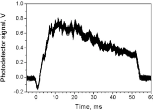
Figure 3 shows the photodetector signal corresponding to the plasma discharge. The amplitude of the plasma current pulse was 27 kA and the pulse duration was 55 ms. It is easy to see that the photodetector signal along with the plasma current response includes signal of random birefringence due to the mechanical perturbation during the electrical discharge. The sensor sensitivity to the plasma current, limited by the laser noise, was measured to be approximately 50 A, which is enough for the plasma current measurements in powerful tokamaks. However, the sensitivity limited by mechanical vibrations, resulting from an acoustical impact wave created by the electric discharge pulse, was around 1 kA.
Figure 3. Plasma current signal from the differential amplifier output.
We experimentally studied the optical compensation for the fiber linear birefringence induced by mechanical vibrations, which may result, for example, from the impact wave mentioned above. The two-pass Faraday current sensor with the variable Faraday mirror was applied in order to investigate the decrease of the vibration influence on the sensor sensitivity. The experimental arrangement of the sensor is presented in figure 4. Radiation at the wavelength 1.15 µm (this wavelength corresponds to the spectral window of the YIG crystal used in the Faraday cell) from the low-power He-Ne laser was passed through a polarizer and beam splitter, and then coupled to the single-mode Lo-Bi fiber wound 10 turns on a 60 cm diameter collar. A piezoelectric modulator was employed to periodically compress a short part of the fiber at a frequency of 10 kHz in order to simulate mechanical perturbations. The “useful” electric current signal was generated by a wire coil, 1000 turns, connected to a sinusoidal current generator with an amplitude of 1 A and frequency of 200 Hz. This coil generated a magnetic field equivalent one produced by single coil with electric current of 1 kA (analogue of the plasma current), and was used to control of the sensor output signal. Radiation from the opposite end of the fiber was passed twice through the 45º variable Faraday cell and then coupled back into the same fiber. The rotation angle of the Faraday cell may be varied slightly (between 40º and 45º) with an additional wire coil. After reflection from the beam splitter the output beam from the fiber was divided by a Wollaston prism into two equal-power orthogonally polarized beams. The output signal from the differential photodetector was recorded by an oscilloscope.
Figure 4. Setup of the Faraday current sensor with the variable Faraday mirror.
1, laser; 2, polarizer; 3, beam splitter; 4 and 6, microscope objectives; 5, single-mode Lo-Bi fiber;
Next Page
7, piezoelectric modulator; 8, calibration coil; 9, current generator; 10, YIG crystal; 11, return mirror; 12, Sm-Co permanent magnet; 13, additional coil for magnetic field variation; 14, Wollaston prism;
15, differential photodetector; 16, oscilloscope.
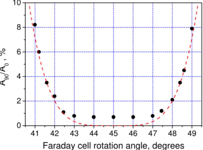
A graph describing the compensation for the fiber linear birefringence is showed in figure 5. The ordinate axis presents the ratio of the modulation depths of the photodetector signals corresponding to mechanical perturbation produced by the wire coil and measured in both cases with (A90) and without (A0) the Faraday
cell. The case of the cell absence corresponds to the non-compensation regime, and one with the cell – to the compensation regime. From the graph it is noticeable that the area for perfect compensation of the mechanical perturbation lies in the range of the angular mistuning no more than δ∼ 2-3° from the exact value of 45°. The maximum compensation obtained in our experiments, approximately 20 dB, is limited, in our opinion, by the non-compensated polarization noise due to the beam reflection from the fiber ends. The value of the sensor signal corresponding to the “useful” electric signal was the same for both compensation and non-compensation regimes. The sensor sensitivity at the wavelength 1.15 µm and one fiber turn was measured to be 1.15 angular seconds/A.
41 42 43 44 45 46 47 48 49 0
2 4 6 8 10
A 90 /A 0
, %
Faraday cell rotation angle, degrees
Figure 5. The ratio of the modulation depths of the photodetector signals with (A90) and without (A0) the Faraday cell versus the cell rotation angle (in degrees).
The dashed curve represents an approximate function for the case where the back reflection from the fiber ends is absent.
4. CONCLUSIONS
We used the Faraday fiber-optic current sensor to measure the tokamak plasma current and demonstrated that proposed technique possesses enough sensitivity. To decrease the influence of mechanical perturbations on the sensor output signal we successfully applied the two-pass optical scheme with the variable Faraday mirror at the fiber end. A reduction, by two orders of magnitude, of the reciprocal birefringence signal simulated by the external piezoceramic modulator, was experimentally observed. The sensor can be used for current measurements in the broad spectrum of applications, especially in powerful electric-ostile-equipment.
5. REFERENCES
[1] ITER concept definition (IAEA, Vienna, 1989).
163
Journal of Applied Research and Technology [3] Rosenbluth, M.N. “Physics fundamentals for ITER”, Plasma Phys. Control Fusion 41 (1999) A99-A113.
[4] Tang, D. A.H.Rose, G.W.Day, S.E.Etzel, “Annealing of linear birefringence in single-mode fiber coils:applications to optical fiber current sensors”, J. of Lightwave Technology 9 (1991) 1031-1037.
[5] Rogers, A.J. J.Xu, J.Yao, “Vibration immunity for optical-fiber current measurement”, J. of Lightwave Technology 13 (1995) 1371-1377.
[6] Clarke, I.G. “Temperature-stable spun elliptical-core optical-fiber current transducer”, Opt. Lett. 18 (1993) 158-160.
[7] Fang, X. A.Wang, R.G.May, R.O.Claus, “Polarization dependence of response function in 3×3 Sagnac optical fiber sensor”, J. of Lightwave Technology 12 (1994) 1504-1509.
[8] Rogers, A.J. “Optical-fiber current measurement”, Int. J. Opt. 3 (1989) 397-407.
[9] Kaliteevski, N. “Optique Ondulatoire” (Mir, Moscow, 1980), p.152.
[10] Cruz, J.L. M.V.Andres, M.A.Hernandez, “Faraday effect in standard optical fibers: dispersion of the effective-Verdet
-constant”,-Appl.-Opt.-35-(1996)-922-926
Author Byography
Yuri O. Barmenkov
Was born in St.Petersburg, Russia, in 1961. He received his M.S. and Ph.D. degrees from St.Petersburg State Technical University (St.Petersburg, Russia) in 1984 and 1991, respectively, all in radiophysics and electronics. At present, Yuri O. Barmenkov is with Centro de Investigaciones en Óptica (Research Center in Optics), A. C. (León, Gto, México). He is co-author of 48 scientific publications and 2 patents. Main research activity includes fiber optic sensors, fiber lasers and nonlinear optical media.
Fernando Mendoza Santoyo
Studied Physics at the Universidad Autónoma Metropolitana (Autonomous Metropolitan University) in Mexico City, has a M. Sc. in Applied Optics from Imperial College, London, and a Ph.D. in Applied Optics from Loughborough University. He was a Research Fellow at Loughborough University and did consultancy jobs for British Aerospace, Rolls Royce, Metal Box and Spectron Laser Systems. Recently, Stuttgart University granted him a visiting professor status to work for an EEC project. Dr. Mendoza founded the Optical Metrology Group and co-founded the Fiber Optics Group, both in the Optical Research Center, where he is the General Director.
Next Page