Abstract—This paper presents the author's experience in programming Field Programmable Gate Arrays (FPGAs) in the context of high performance digital signal and data processing. In particular, the paper presents the concept of hardware skeletons as a mean to bridge the gap between high level applications and low level hardware, and satisfy the dual requirement of high level abstract design and hardware efficiency. The concept will be illustrated in the context of image/video processing applications among other applications. In using and developing a variety of hardware design tools, the author will finally suggest a multi-language approach to hardware development.
Index Terms— FPGAs, reconfigurable hardware, optimizing compilers, hardware skeletons, image and video processing.
I. INTRODUCTION
Today’s system programming is characterized by a widening gap between applications on the one hand and hardware technology on the other. Indeed, applications are getting more and more complex as a result of growing customer demands for services such as video communication and internet applications. Hardware integration levels are also increasing at an exponential rate thanks to a continuous observation of Moore’s law. If we add to this widening gap between applications and hardware constant market pressure to keep costs low and reduce products time-to-market, it soon becomes clear that the job of system developers is getting harder and not easier.
Overall, computer platforms can be classified into four primary groups: 1) General purpose processors (GPPs), 2) Application-Specific Instruction-set Processors (ASIPs), 3) Field Programmable Gate Arrays (FPGAs), and 4) Application-Specific Integrated Circuits (ASICs). The first two groups are software reprogrammable based on the Von-Neumann architecture with the first used for general purpose computing (e.g. Pentium Processors), whereas the instruction set and corresponding hardware of the second are specifically tailored to a particular application area (e.g. DSP processors). FPGAs on the other hand have a user-defined architecture as the hardware is configured, and often reconfigured, on the field by customers. At the other end of the spectrum, ASICs present a fully customized hardware
Manuscript received October 9, 2007. This work was supported in part by the U.K. Engineering and Physical Sciences Research Council (EPSRC) under Grant GR/R72846/01.
Dr. Khaled Benkrid is with the Institute of Micro and Nano Systems, School of Engineering and Electronics, University of Edinburgh, Scotland, Edinburgh, EH9 3JL (phone: 0131-650-5666; fax: 0131-650-5446; e-mail:
implementation to the algorithm in hand with the best performance and power consumption figures possible. They are usually non-reprogrammable however which limits their application to high volume, relatively low cost, and low power applications.
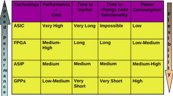
Figure 1 compares the above four platforms in terms of performance/cost ratio, time to market, time to change code functionality, and power consumption.
S p e e d
P e r f o r m a n c e
Very Short Medium Long Impossible
Time to change code functionality
High Medium-High Low-Medium Low
Power Consumption
Long Medium-High FPGA
Very Short Low-Medium GPPs
Medium Medium
ASIP
Very Long Very High
ASIC
Time to market Performance
/ Cost Technology
F l e x i b i l i t y
Figure 1. Comparison summary between various computer platforms
It is clear from the above that FPGAs provide a middle solution between ASICs and GPPs/ASIPs. Indeed, unlike ASIPs/GPPs, FPGAs are not constrained by the Von Neumann architecture as illustrated in Figure 2 where a 256-tap FIR filter implementation is shown both in GPPs/ASIPs and FPGAs. In this, FPGAs can instantiate as many Multiply-Accumulate (MAC) units as possible, whereas GPPs/ASIPs are constrained by the sequential nature of their processing. This allows FPGA to achieve much higher performance figure than GPPs/ASIPs (typically 100x). Besides, FPGAs have ASIC-like performance and power consumption, with the additional reprogrammability feature. FPGAs have also a shorter development cycle and lower Non-Recurring Engineering (NRE) costs compared to ASICs.
High Performance Reconfigurable Computing:
From Applications to Hardware
Khaled Benkrid, Senior Member, IEEE
Figure 2. GPP/ASIP vs. FPGA implementation of a 256-tap FIR filter (Source: www.xilinx.com)
However, while the above clearly favors FPGAs over other competing technologies, FPGA programming remains hardware–oriented which makes FPGA programmer productivity far inferior to that of GPP/ASIP programmers. Even with improving hardware description and synthesis environments [1][2][3][4][5], FPGA programming is still reserved to specialists. This represents a major hurdle to the dissemination of FPGA technology into a wider pool of users. This paper presents the author’s own experiences in surmounting this obstacle and presents his view as to how the FPGA programming community should proceed.
The remainder of the paper is organized as follows. First, the overall FPGA programming model adopted by the author is presented. Central to this is the concept of hardware skeletons which will be illustrated in the context of image and video processing applications, as well as a two-stage compilation strategy with an intermediate hardware notation. The paper will then present achievements using this approach, and discuss future developments in light of increased complexity both in hardware and implementation. Finally, a conclusion is drawn up.
II. FPGA HIGH LEVEL PROGRAMMING MODEL
With ever increasing complexity of FPGA hardware on the one hand and increased complexity of applications on the other hand comes the need for sophisticated design tools to bridge the resulting gap. Two conflicting constraints however act on tool developers: first, the need for higher level application abstraction and, second, the need to retain hardware efficiency. The key to achieve an acceptable compromise between these two conflicting requirements are optimizing compilers.
The author preferred approach to bridge this gap is a direct “application to hardware” development process whereby application developers design and program FPGAs from a model-based application-oriented description. The key to retain hardware efficiency is the concept of “hardware skeletons” which the author has developed in Year 2000 [3]. Hardware skeletons are reusable frameworks which take not only variables, but also functions or other skeletons as parameters. Until fully parameterized, a hardware skeleton does not perform any functionality. Functionality, rather than data, is sent as a parameter, something that makes this approach the opposite of traditional hardware design approaches where functionality defines blocks and data, rather than functionality, is passed as a parameter. Hardware skeletons also contain built-in rules that apply optimizations inherent to the skeleton, and customized to the supplied parameters which include target hardware. By composing skeletons hierarchically and by performing optimizations at each stage of the hierarchy, the aforementioned dual requirement of hardware efficiency and abstract design can be achieved.
A. Examples of Hardware Skeletons
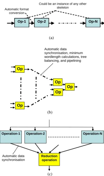
Figure 3 presents three examples of hardware skeletons. The first, the pipeline skeleton, is ubiquitous in hardware as it
is one of two main ways of achieving parallelism [6]. The pipeline skeleton presented in Figure 3.a consists of a cascade of generic stages where the output of each stage is the input of the subsequent one. A user can define the functionality of a pipeline stage which can range from a simple addition or multiplication to a skeleton of any other type, as well as the type and range of input. One optimization that the skeleton rules can apply is to interface between subsequent stages by automatically inserting the necessary hardware for format conversion (e.g. bit serial to bit parallel, sign extension etc.) depending on the parameters of the pipeline stages.
Op-1 Op-2 Op-N
Could be an instance of any other skeleton
Automatic format conversion
(a)
Op Op
Op
Automatic data
synchronisation, minimum wordlength calculations, tree balancing, and pipelining
Op
Op
(b)
Automatic data synchronisation
Operation-2 Operation-N
Reduction operation Operation-1
(c)
Figure 3. Hardware skeleton examples
The second example presented in Figure 1.b is the reduction skeleton which reduces an array of inputs into a single output. Here too, the user can specify the particular reduction function e.g. addition, multiplication, maximum, and minimum, as well as the type and range of data inputs. The skeleton has built-in optimizations, which automatically synchronizes data across stages; infer the minimum necessary word length(s); and balance and pipeline the tree to a user-desired level.
The third example presented in Figure 3.c is the parallel operations skeleton and consists of N parallel operations,
which could be instances of other skeletons, all operating on the same input. The outputs of these operations are then reduced to one single output. Here, the user can specify any skeleton in the parallel branches (e.g. a pipeline skeleton) and any reduction operation. He/she can also specify any type and range of input data. The skeleton built-in rules will automatically infer the proper processing word lengths, synchronize and adapt data at the interfaces.
B. FPGA High Level Programming Model
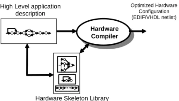
Equipped with a hardware skeleton library, an application developer’s task is simply to choose skeletons from the library, parameterize these skeletons according to the application needs, and combine skeletons in the appropriate manner. Preferably, this would be done through a graphical interface. A hardware compiler would then take the resulting application description in terms of hardware skeletons and generate optimized hardware automatically from it (see Figure 4).
Hardware Compiler
Hardware Skeleton Library High Level application
description
Optimized Hardware Configuration (EDIF/VHDL netlist)
Figure 4. Proposed skeleton-based FPGA hardware development
In the author’s approach, this compilation process is done in two stages. First, the application description is compiled into a hardware-independent description (much like object code in software) before a netlist generator produces the corresponding optimized hardware for a particular implementation platform. This is done for the sake of modularity and portability as it is the custom is software engineering. With this in mind, Figure 5 presents the two stage hardware development model.
High Level Generator
Hardware Skeleton Library
High Level application description
Optimized Hardware Configuration (EDIF/VHDL netlist)
Netlist Generator Intermediate
Notation
Basic Building Blocks Hardware Library
+ x
< < > >
Figure 5. A two-stage hardware development model
C. The intermediate notation: HIDE
The intermediate notation adopted by the author is called HIDE (Hardware Intelligent Description Environment) [7]. HIDE describes scaleable and parameterized hardware
architectures in a structural way. Its main features can be summarized by the following four aspects:
1- Layered Hardware Block Library: In HIDE, hardware is assembled using a range of components with different levels of abstractions as illustrated in Figure 6.
Fixed Basic Component Library
Compound components Parameterised Basic Components Library
e.g. 1 or 2 bit adders e.g. N-bit adder, NxM multiplier e.g. parameterised
FIR filter
Figure 6. Layered architecture of HIDE’s hardware library
At the bottom level, fixed basic components are found. These include, for instance, bit adders, bit multipliers, and bit delays. This layer is the closest to the underlying hardware. Different versions exist for different FPGA architectures. The second layer of the library contains parameterized basic components such as generic N-bit adders and generic NxM multipliers. At the top level, the library contains compound components such as fully parameterized FIR filters. Overall, each layer depends on the lower level layers and builds its components from these layers. It is this hierarchy of blocks which applies relevant optimizations at each stage that helps bridge the gap between high level applications and low level hardware while keeping the high performance.
2- Architecture Description: In HIDE, a hardware block is rectangular with input/port ports and control signals at the four sides (north, south, east and west). Such blocks are assembled in a structural way using a small set of 2D and 3D constructors, including horizontal and vertical constructors (see Figure 7) in the case of 2D, and the above operator in the case of 3D (see Figure 8). Note that connectivity need not be explicitly specified in HIDE as it automatically figures out which ports connects to which using a simple heuristic which connects input ports on one side to output ports on the other side and vice versa following a default order.
C = vertical([B1,B2])
C = horizontal([B1,B2])
B1
B2
6
B1 6
B2
Figure 7. Horizontal and vertical constructors in HIDE
C=above([B1,B2, B3])
B2
B1
B3
Figure 8. Above constructor in HIDE
An architecture builder in HIDE can specify particular connectivity between blocks, if he/she does not want to rely on the automatic routing heuristic, using the network connector (nc) construct (see Figure 9).
B2
B1
2
1
4
3
6
5
8
7
nc
C= horizontal([ B1, nc([ p_seq(i, 4, [(i, i+4),(i+4, i)])]), B2 ])
Figure 9. Butterfly network connection in HIDE
HIDE can also describe systolic array architectures very concisely using parameterized constructors such as the horizontal and vertical sequence constructors (see Figure 10).
C = v_seq(i, 3, h_seq(j, 4-i, B1))
C = h_seq(i, 3, v_seq(j, i, B1))
B1
B1
B1
B1
B1
B1
B1
B1
B1
B1
B1
B1
Figure 10. Parameterized horizontal and vertical constructors in HIDE
In HIDE, the two concepts of block interconnection and block placement can be separated. Different topologies can thus be built, while retaining the same block connectivity, through the use of layout managers which can over-ride the default placement information to implement a particular topology. Figure 11 illustrates this concept with the example of the triangle layout manager.
B
He
ight
Width
triangle(B, Width, Height)
Figure 11. The triangle layout manager in HIDE
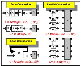
In addition to the above structured constructors, HIDE offers logical constructors which perform certain connectivity without implying any geometrical placement. These are the serie/s_seq, par/p_seq, and loop constrictors as illustrated in Figure 12.
Serie Composition
C= serie([B1, B2,…., Bn])
=
B2 BN
B1
C= s_seq([N, B])
Parallel Composition
C= p_seq([N,B]) C= par([B1, B2,…., Bn])
Loop Composition
C= loop([B, nc([(1,2])])
B
C
=
B B
B C
C
=
= C
B1
B2
B3
BN
= C
B B B B
Figure 12. Logical constructors in HIDE
3- Architecture Control: Control signals (e.g. clock, clock enable, and clear signals) are treated differently from normal ports as they are usually broadcast to a large number of components on chip. They are represented and manipulated using different structures.
4- Architecture Constraints: In addition to architecture description, HIDE offers architecture builders the possibility to attach placement, routing, timing constraints, and possibly power constraints to hardware blocks. These are taken into consideration whenever possible by the rule-based skeleton assembly mechanism, and/or passed to back-end synthesis tools.
The above four aspects sub- ensure a separation of concerns which results in a highly modular development environment. Figure 13 below illustrates the HIDE hardware development process.
Composition Process
EDIF Generator HIDE Composition
Data Structure
Objects Description
Library
EDIF
Placement and Routing Tool Architecture
Builder
Basic Components
Library
VHDL VHDL Generator
Figure 13. HIDE hardware development process.
Figure 14 illustrates an example of a fully parameterized parallel matrix multiplier description in HIDE alongside the resulting implementation. The EDIF netlist generated for a 3x3 by 3x3 matrix multiplier contains all the placement information and was generated in few seconds. The resulting FPGA configuration matches hand-crafted vendor implementations with the added benefit of being programmatically generated and invoked. The result of the HIDE function call (or predicate call since HIDE was written in Prolog) could indeed be used a parameter for a subsequent function call which assembles a much complex block or skeleton.
Generic full matrix multiplier
FPGA
configuration
Figure 14. Parallel Matrix Multiplier description and implementation in HIDE
Table 1 gives implementation results of the matrix multiplier core on Virtex XCV2000E-6 for different matrix sizes (for 8-bit processing word length).
TABLE 1. IMPLEMENTATION RESULTS OF THE MATRIX MULTIPLIER ON
VIRTEX XCV2000E-6 FPGAS
Matrix Speed (MHz) Area (slices) 2x2 (8 bits) 186 352
3x3 (8 bits) 145 1305 4x4 (8 bits) 131 2960
III. APPLICATION- ORIENTED ABSTRACTIONS: IMAGE AND
VIDEO PROCESSING
Figure 15 below illustrates the direct application to hardware design approach. In it, application developers describe the algorithm in hand using application-oriented skeletons. The application developer chooses and parameterizes skeletons, and combines them according to his/her algorithm needs. Skeleton-specific optimization rules are then automatically applied by the high level generator which then produces hardware descriptions in HIDE. The HIDE system then
generates optimized hardware netlist for a specific hardware platform in the form of EDIF or VHDL.
Build the algorithm in terms of parameterised skeletons
Built-in optimisation rules are applied
Generate configuration (in EDIF)
HIDE
[ Place and ] Route
FPGA Application Developer
Figure 15.Overview of our direct application to hardware design flow
In the context of image and video processing, this approach was used successfully by the author and his group to implement high level environments for FPGA-based image and video coprocessor [8][9][10]. Figure 16 illustrates an instance of a pipeline skeleton which performs an absolute Laplace edge detection with binary thresholding [11]. Here, all the application developer has to do is to instantiate a pipeline skeleton with three stages with each stage parameterized with a particular function (convolution for the first, absolute operation for the second, and threshold for the third).
Pipeline skeleton
Op-1 Op-2 Op-N
-1 -1 -1
-1 ~ ~
4 ~ ~
Convolution
Absolute (point operation)
Threshold (>Thresh)
Absolute Laplace with threshold
instance
Figure 16. Pipeline skeleton
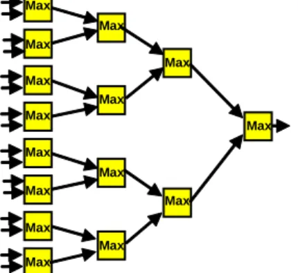
The second example, presented in Figure 17 presents two instance of the reduction skeleton, namely adder reduction and maximum reduction. Again, the application developer has, only, to instantiate the reduction skeleton with 16 inputs and an adder/maximum reduction operation respectively. The type and range of inputs is also a parameter, as it is in the pipeline skeleton example of Figure 16.
+
+
+
+ +
+ +
+
+
+ +
+
+
+
+
(a) 16-input Adder Tree
Max Max
Max Max
Max
Max
Max Max
Max
Max
Max
Max
Max
Max
Max
(b) 16-input Maximum reduction tree
Figure 17. Reduction skeleton
The third example presented in Figure 18 illustrates the parallel operations skeleton through two instances, namely the Sobel and Prewitt operators. Here, the application developer instantiates the parallel skeleton with two branches, each branch consisting of a two-stage pipeline skeleton. The reduction operation is an image to image addition. The underlying generator will automatically generate optimized hardware netlist from such high level description with an intermediate notation in HIDE notation.
Operation-2 Operation-N
Reduction operation Operation-1
(a) Parallel operations skeleton
Image-Image addition
2 1 1
-2 -1 -1
Convolution
-2 -1 -1
2 1 1
Convolution
Absolute Absolute
(b) Sobel operator
Image-Image addition
1 1 1
-1 -1 -1
Convolution
-1 -1 -1
1 1 1
Convolution
Absolute Absolute
(c) Prewitt operator
Figure 18. Parallel operations skeleton
The fourth example presented in Figure 19 illustrates the “Process and Reduce” skeleton through an instance which implements a perimeter detector. The skeleton instance is an additive-maximum neighborhood operation which performs an erode operation. The perimeter is then deduced by subtracting the eroded image from the original image [12].
0
0 0
0
~ ~
0 ~ ~
Add-Minimum
Image-Image Subtraction “Process and Reduce” skeleton
Reduction
Skeleton
Perimeter detector Figure 19. Parallel operations skeleton
Another example of hardware skeletons for image and video processing is presented in Figure 20 and performs a 2D multivariate filtering with generic L and H FIR filters [13]. An instance of this skeleton presented in Figure 21.b implements a generic 3-stage 2D wavelet transform parameterisable in terms of low (L) and high (H) filter coefficients, image word length. Built-in optimizations include: dynamic word length across stages according to the dynamic range required, novel error cancellation techniques, and efficient border signal handling [14][15]. This implementation was the fastest 2D wavelet FPGA implementation at the time of its publication and outperformed an equivalent software implementation by over 200:1.
÷2
÷2
÷2
÷2 H
L ÷2
÷2
H
L
H
L N/2
N/2 Δ N/2 Δ N/2 Δ N/2 Δ
NxN
N/2
Transpose
(a) A generic multi-variate 2D filter
÷2
÷2
÷2 H
L ÷2
÷2 H
L
H
L
N/2 ÷2
÷2
÷2 H
L ÷2
÷2 H
L
H
L
÷2
÷2
÷2
÷2 H
L ÷2
÷2 H
L
H
L
N/16 N/8
NxN
(b) A 3-stage 2D wavelet transform
Figure 20. Parallel operations skeleton
Using this approach, FPGA-based image and video co-processors based on the abstraction of Image Algebra have been implemented and tested on real FPGA hardware e.g. VigraVision’s FPGA-based video board and Celoxica RC1000 FPGA-based PCI board. In these environments, applications developers program FPGA hardware using an application-oriented interface. The concept of hardware skeleton allows for the generation of optimized hardware from abstract application descriptions with real time performance for video applications achieved with a considerable margin [7][8][9].
IV. DEALING WITH INCREASED COMPLEXITY
Reconfigurable hardware is getting more and more complex with increased complexity and heterogeneity. Indeed, the latest FPGAs have a variety of embedded ASIC DSP blocks (e.g. MACs, Block RAMs) as well as embedded processors and various input/output capabilities. Faced with this, FPGA hardware designers are turning into higher level design environments such as System-C, Handel-C and other C-based high level languages. Handel-C, for instance, allows application developers to program FPGAs in a C-like syntax with higher level software-like abstractions which makes it easier to port existing legacy software code into hardware. Nonetheless, being a high level hardware language, Handel-C lacks the hardware efficiency provided by HIDE, for instance. Table 2, for instance, shows comparative implementation results of a 3x3 Gaussian smooth filter (see Figure 21) on FPGAs using HIDE, Handel-C and RTL VHDL [9].
Figure 21. A Gaussian smooth filter kernel (the operation is a convolution)
TABLE 2. COMPARATIVE IMPLEMENTATION RESULTS OF A 3X3 GAUSSIAN
FILTER ON XILINX VIRTEX-E2000-6 FPGAS
Speed (MHz)
Area (Slices)
Block RAMs
Development times HIDE
implementation
132 284 2 3 person-weeks RTL VHDL
implementation
88 360 2 7 person-days Handel-C based
implementation
71 404 2 5 person-days
The HIDE implementation development time includes the time it took to develop the basic building blocks in the library.
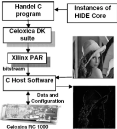
As can be seen, HIDE implementations largely outperform Handel-C implementations (often 30-50% more in speed and area) but take considerably more to develop. The RTL VHDL implementation sits between the two. The traditional way designers have dealt with this problem has been to adopt the closest language to their cost, functionality and performance requirements. The author, however, posits the following: Why should designers choose between languages? Why could not they harness the combined strengths of complementary design languages/environments? The reason why this has not been largely possible is partly because of a marketing element. Indeed, electronic design automation tool vendors are not enthusiastic about making their tools interoperable with competitors’ tools. However, the return for users can be greatly enhanced if that was possible. As an experiment, the author has successfully combined the Handel-C and HIDE environments by using Handel-C as the top level design language with calls to high performance HIDE cores using a standard interface construct (see Figure 22). This harnesses the high performance of HIDE for datapath units with Handel-C’s ease of use for control paths [9]. This combination can be extended to any other environment given the following:
•
Use of a standard interchange notation (e.g. EDIF in the HIDE/Handel-C combination)•
Source level Co-simulation, which needs common simulation syntax. This was done at the EDIF level in our case study as it was very difficult to produce or find a common source level simulator (due mainly to lack of vendor support and instability of existing simulation tools)•
Dynamic calls from one environment to another should be supported. This was not supported in the Handel-C DK environment, so a wrap-around layer on the top of the Handel-C language had to be custom-designed by the author’s teamFigure 22. Combined Handel-C/HIDE design flow
V. CONCLUSION
This paper presented the author’s experience in programming Field Programmable Gate Arrays (FPGAs) for high performance reconfigurable computing. One the main achievements of the author in this regard is the concept of hardware skeletons as a way to satisfy the dual requirement of high level design and hardware efficiency. The paper
illustrated this concept particularly in the context of high performance FPGA-based image and video processing. In developing and using a wide range of electronic design automation tools, the author proposes the following: instead of striving towards the most encompassing super hardware design language that will meet user demands in term of performance, ease of use and cost, the community has to learn from similar failed experiences in the software engineering realm, and strive towards developing standards for easy (dynamic) inter-operability of existing complementary tools. In the author’s opinion, a multi-language hardware design approach will become more of a necessity in the future as both hardware and applications continue to grow in complexity.
ACKNOWLEDGMENT
The author would like to thank the UK Engineering and Physical Sciences Research Council for supporting part of the research presented in this paper under Grant GR/R72846/01. He would also like to thank his PhD students and colleagues at the Queen’s University of Belfast and the University of Edinburgh for their support.
REFERENCES
[1] B. Hutchings et al., “A CAD suite for high-performance FPGA design”, in Proceedings of IEEE Symposium on Field-Programmable
Custom Computing Machines, FCCM’99, 1999, pp. 12–4.
[2] S. Singh, “System level specification in lava”, in Proceedings of the
Conference on Design Automation and Test in Europe, DATE (2003)
10370.
[3] K. Benkrid, D. Crookes, “From application descriptions to hardware in seconds: a logic-based approach to bridging the gap”, IEEE Transactions on Very Large Scale Integration (VLSI) Systems, TVLSI 12, vol. 4, 2004, pp. 420–436.
[4] Celoxica Limited, Handel C information sheets. Available from: <http://www.celoxica.com>.
[5] System C Home page. <http://www.systemc.org>. [6] S.Y. Kung, “VLSI Array Processors”, Prentice Hall, 1988.
[7] K. Benkrid, S.Belkacemi, A. Benkrid, “HIDE: A Hardware Intelligent Description Environment”, In Elsevier's Journal of Microprocessors
and Microsystems, Special Issue on FPGA-based Reconfigurable Computing, 30, Vol. 6, pp. 283-300, September 2006.
[8] K. Benkrid, D. Crookes, J. Smith, A. Benkrid, “High Level Programming for Real Time FPGA Based Video Programming”, In
Proceedings of the IEEE International Conference on Acoustic, Speech and Signal Processing, ICASSP'2000, Istanbul, June 2000. Volume
VI, pp. 3227-3231.
[9] K. Benkrid, S.Belkacemi and S. Sukhsawas, “An Integrated Framework for the High Level Design of High Performance Signal Processing Circuits on FPGAs”, In Proceedings of SPIE Opto-Ireland, Vol. 5823, No. 29, pg. 12, 2005.
[10] K. Benkrid, S. Sukhsawas and S. Belkacemi, “Fast Prototyping of an FPGA-Based High Level Image Coprocessor Using Handel-C”, In
Proceedings of SPIE Opto-Ireland, Vol. 5823, No. 15, pg. 12, 2005
[11] K.R. Castleman, Digital Image processing, Prentice-Hall, 1995, ISBN 0132114674.
[12] K. Benkrid, D. Crookes and A. Benkrid, “Design and FPGA Implementation of a Perimeter Estimator”, In Proceedings of the Irish
Machine Vision and Image Processing Conference, IMVIP'2000,
Belfast, September 2000, pp.51-57.
[13] A. Benkrid, D. Crookes, K. Benkrid , “Design and implementation of a generic 2D orthogonal discrete wavelet transform on FPGA”, In
Proceedings of the 11th Annual IEEE Symposium on Field-Programmable Custom Computing Machines, FCCM 2003, pp.
162 -172, 9-11 April 2003
[14] A. Benkrid and K. Benkrid, “Handling finite length signals borders in two-channel filter banks for perfect reconstruction”, Elsevier's Journal of Signal Processing, Vol. 86. pp 375-387, February 2006
[15] A. Benkrid, K. Benkrid, D. Crookes, “The Optimal Wordlength Calculation for Forward and Inverse Discrete Wavelet Transform
Architectures”, SPIE Journal of Optical Engineering, OE, Vol. 43, Issue 2, pp. 455-463, February, 2004.
Dr. Khaled Benkrid was born in
Algiers on 12 November 1975. He holds an Ingenieur d’Etat in Electronics Engineering from Ecole Nationale Polytechnique d’Alger, a PhD in Computer Science and an Executive MBA from Queen’s University Belfast, UK.
He is now a Lecturer in the School of Engineering and Electronics at the University of Edinburgh, Scotland, UK, after having spent six years as a Lecturer in Computer Science at Queen’s University Belfast. With over ten years experience in FPGA hardware design, he has authored over 50 publications in major international journals and conference papers in the areas of high performance reconfigurable computing and electronic design automation. He continues to be active in these areas with applications in digital signal processing, bioinformatics and computational biology, and scientific computing.
Dr. Khaled Benkrid is a Senior Member of IEEE and a Chartered UK Engineer. He has served as program committee member and session chair at many international conferences including the IEEE 2004 ISVLSI conference and the 2007 NASA/JPL Adaptive Hardware Systems conference. He is the holder of various research grants from the UK government, the EU, and Industry.