Abstract— This paper presents the application of frequency selective surfaces in antenna arrays as an alternative to improve radiation parameters of the array. A microstrip antenna array between two FSS was proposed for application in WLAN and LTE 4G systems. Several parameters have been significantly improved, in particular the bandwidth, gain and radiation efficiency, compared with a conventional array. Numerical and measured results are presented.
Index Terms—FSS, LTE, Microstrip Antena Array, WLAN.
I. INTRODUCTION
The development of telecommunications in recent years has given rise to a variety of services that
use a specific frequency band for operation. Some of these services are designed to access the Internet via wireless networks, such as WLAN (Wireless Local Area Network), UMTS (Universal Mobile
Telecommunications System) and LTE (Long Term Evolution) through mobile terminals, such as laptops or cell phones.
WLAN based networks (2400 to 2483.5 MHz) had a very rapid expansion due to numerous advantages such as the absence of wires between users and access points, which provide greater
flexibility in the reception area, allowing the access to many locations, making it possible to create ad-hoc networks without prior planning, and facilitating the establishment of these networks.
In the field of mobile telephony we have, as a first example, the service of cellular, or WWAN (Wireless Wide Area Network), comprising the sub-band UMTS (1920 to 2170 MHz), which is part of the third generation technology, and LTE (2500 to 2690 MHz), which is part of the fourth
generation technology, which was developed with the goal of bringing to cell phones, video, image
and a higher speed access to the Internet.
Since each service operates at specific frequency bands, and in some cases with polarization and different radiation characteristics, it is necessary to integrate different antennas at the devices. To
avoid the use of several antennas to operate the services, one possible solution is to use compact multi-band or broadband antennas.
Performance Optimization of Microstrip
Antenna Array Using Frequency Selective
Surfaces
Valdez A. Almeida Filho
1, Antonio Luiz P. S. Campos
2,
1
Graduate Program in Electrical and Computational Engineering Federal University of Rio Grande do Norte (UFRN)
Av. Senador Salgado Filho, 3000, Natal, RN, Brazil, CEP: 59072-970 Tel.: +55-21-84-3215-3767, e-mail: [email protected]
2
Communication Engineering Department Federal University of Rio Grande do Norte (UFRN)
These antennas must have low cost, minimum weight, low profile and they must be able to maintain
good performance over the frequency bands for which they were designed to operate. This technological trend has focused much on the design of microstrip antennas. With a simple geometry, the microstrip antennas offer many advantages that normally do not appear in other type of antennas.
In contrast, the microstrip antenna offers the drawback of displaying a narrow bandwidth and low
gain, low directivity, and low radiation efficiency to the simplest forms, which restricts their use [1], [2].
When some radiation parameters are not achieved with a single radiating element, we can use a
technique that consists in associating radiating elements in a geometric and electrical configuration. This new antenna formed by multiple elements is the microstrip antenna array. In addition to
increasing the bandwidth, with an array we can obtain higher levels of gain and directivity compared with a microstrip antenna [3], [4].
The microstrip antenna arrays have many applications in the area of Telecommunications. Among the latest applications found in literature, we can mention the use of arrays for satellite
communications [5], [6], applications in L-band networks for GNSS/GPS [7] in wireless sensor networks [8] and textile substrates for communications centered on the human body [9]. A microstrip
array using multilevel elements based on fractal geometry was proposed to obtain high-directivity, to reduction the size of the array, fractal geometry was used, thus reducing the complexity of the feeding network and the overall array [10].
Although microstrip arrays can be used in several applications. One of the problems of using arrays is related to the occupied space, since arrays have, for the most part, higher dimensions compared
with single antennas. Another frequent problem is related to gain and directivity. To obtain higher levels of gain and directivity we must put more elements in the array. This leads to an increase in the
dimensions of the structure.
One way to solve arrays’ problems is the application of frequency selective surfaces (FSS) to the
antenna array. Such interaction has the purpose of obtaining desired radiation characteristics for the antenna array from changes in their radiation parameters, such as bandwidth, gain and directivity.
Another method to overcome the limitations of arrays is use of optimization techniques to design a single element antenna having similar performances as arrays, but with a lower patch area [11].
Frequency selective surfaces have been applied to antenna or antenna array in order to increase bandwidth in [12], [13]. The authors used an FSS EBG structure, it had characteristic bands insertion of operating/rejection in a given structure, achieving an increase in bandwidth of a specific antenna or
antenna array. The increase in parameters such as gain and directivity using FSS applied to antennas
and antenna arrays have been reported in [14], [15]. We can also mention the use of FSS to reduce the radar cross section (RCS) [16]. Other applications of FSS in microstrip antenna arrays found in literature are in multiband and high-directivity microstrip patch antenna arrays [17], [18].
microstrip antenna arrays (bandwidth, gain, directivity, front-to-back ratio and reduced surface waves)
through the use of frequency selective surfaces (FSS) coupled with the array. To realize this study, we designed two arrays of microstrip antennas. A conventional array and one with truncated ground plane, in order to increase the bandwidth and miniaturize the elements of the array. In the second
array we applied two FSS to obtain better radiation parameters. The results show that the new array
integrated with the FSS has better gain, radiation efficiency, bandwidth and reduced surface waves, when compared to the arrays without FSS.
II. PROPOSED ARRAY
The design of the proposed array starts with a design of a conventional array, narrow band, used to
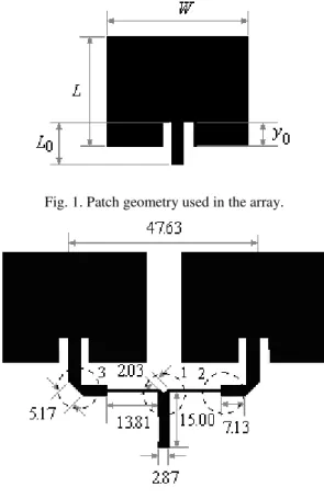
operate in WLAN frequency band (centered at 2.45 GHz). The geometry used was a rectangular patch with inset fed, as shown in Fig. 1. The inset fed is used to improve the impedance matching between
the element and the feed line.
The dimensions of the patch are: W = 37.34 mm, L = 29.09 mm, y0 = 6.19 mm e L0 = 14.52 mm.
The feed is obtained through a microstrip line, since it facilitates the integration of the array with other RF circuits. The substrate used was the fiberglass (FR4) with εr = 4.4 and h = 1.6 mm, due to
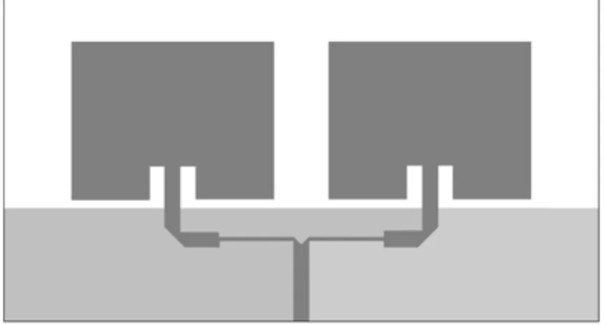
their low cost and facility to buy it. For the present study we designed an array with two elements. Fig. 2 illustrates the geometry of the array with all dimensions used and the discontinuities in feed
network.
Fig. 1. Patch geometry used in the array.
The feed network of the array was designed for the signal can reach the antennas in a same way.
For the distribution of the equalized signal to both elements of the array, some discontinuities have been incorporated in feed lines that make up the network. The discontinuity circulated with the number (1) is called T-junction and it is, perhaps, one of the most important discontinuities of devices
used in microstrip. The T-junction is designed to divide equally the signal to both elements of the
array. The discontinuity (2) known as impedance transformer is intended to obtain an impedance matching of the microstrip lines with different impedances. Finally, the discontinuity (3) called bend is used to introduce flexibility in the layout design of the feed network. The cuts in existing
discontinuities (1) and (3) are intended to compensate losses caused by such discontinuities. The dimensions of the feed network were calculated from formulas found in traditional literature [19].
The array was designed to operate in IEEE 802.11 b/g/n, at 2.45 GHz, with a minimum bandwidth
of 83.5 MHz (3.41% fractional bandwidth), and an input impedance of 50 . After designing, the
array was simulated with Ansoft HFSS. The parameters obtained were: reflection coefficient (S11),
radiation pattern, gain, input impedance, directivity, surface waves (electric field), half power angle,
radiation efficiency and front-to-back ratio. For a frequency of 2.45 GHz the input impedance
obtained with the simulation was 50.9 and the bandwidth was 127 MHz (5.18% fractional
bandwidth), which meets the requirements of the desired application. The simulated gain for that
frequency was 4.46 dBi and directivity was 7.23 dB.
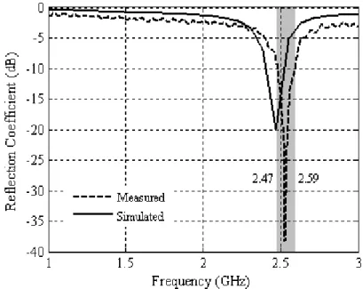
After simulation, the array was built and S11 measurements were performed with a vector network
analyzer ZVB-14 model, from Rohde & Schwarz. As can be seen in Fig. 3, there is a good agreement between measured and simulated results. The measured results show a resonance frequency of 2.53
GHz. The small difference points to an error of – 3.26 %.
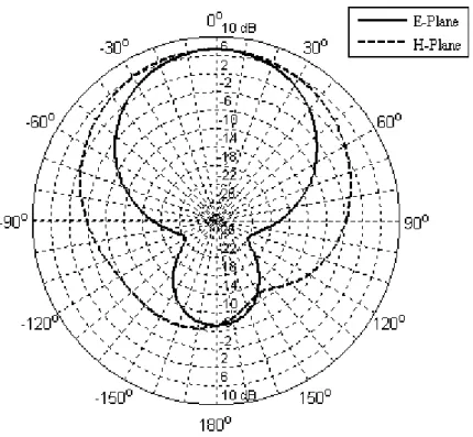
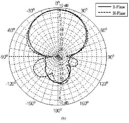
In addition to the simulated results, the radiation patterns in the E and H planes are illustrated in
Fig. 4, at the frequency of 2.45 GHz. From the radiation pattern some parameters were obtained. The half-power angle for this array was 40o. The radiation efficiency was around 53% and the
front-to-back ratio was 14.6 dB.
Fig 4. Radiation pattern for the conventional array.
III. PROPOSED FSS
We are proposing a new configuration of microstrip antenna array integrated with FSS. This configuration presents improved performance of many parameters. The idea is to employ this new
configuration in WLAN and LTE 4G technologies. To improve some parameters such as gain, surface waves, radiation efficiency, directivity and front-to-back ratio, we use a reflector formed by a
stop-band FSS and a FSS superstrate formed by a stop-band-pass structure.
The proposed FSS are designed to operate in the frequency range 2 – 3 GHz, with resonance
frequency at 2.45 GHz. The chosen geometry was the square loop element in both FSS. The choice of this geometry is because, besides having square loop stability and polarization angle, we can reduce
Q
1
Q
2
(a) (b)
Fig. 5. Geometry of the FSS element: (a) stop band and (b) band pass.
The dimensions of the designed FSS are as follow: Q1 outer square (19 mm 19 mm) inner square
Q2 (16.85 mm 16.85 mm) and a periodicity of 20 mm in both x and y directions. The number of the
elements used in the FSS was 72 (8 rows and 9 columns each).
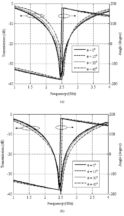
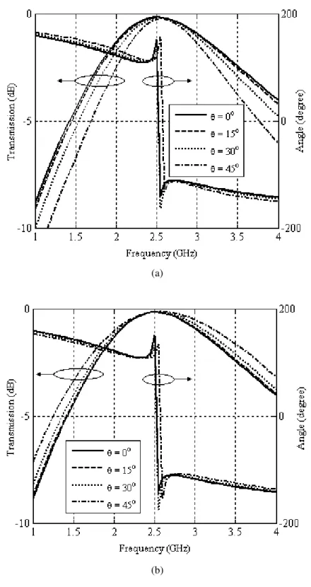
Based on the resonance frequency curves of the transmission coefficient of the FSS stop-band
designed as a function of frequency for angles of incidence between 0° – 45° for both wave polarizations (horizontal and vertical) are shown in Fig 6(a) and 6(b).
As can we can see in Fig. 6 the rejection bandwidth is bigger than 2 GHz (2 – 3 GHz) for various angles of incidence and vertical and horizontal polarization. The results show that for the desired
range of operation (2.4 – 2.7 GHz) the FSS provides angular and polarization stability for a – 10 dB level. Additionally, the FSS has a linear frequency response for the angle of the reflection coefficient
within the desired bandwidth, which can be very useful in pulsed systems, in which a linear phase may be a prerequisite.
Fig. 7(a) and 7(b) illustrate the bandwidths of transmission coefficient for the band-pass FSS for
horizontal and vertical polarizations, respectively, and for several angles of incidence. It can be seen that the FSS has an insertion loss less than 0.5 dB in the desired range of operation (2.4 – 2.7 GHz).
(a)
(b)
(a)
(b)
Fig. 7. Transmission and phase of the reflection coefficient versus frequency for FSS pass-band: (a) horizontal polarization and (b) vertical polarization.
IV. PROPOSED ARRAY WITH OPTIMIZED PARAMETERS
As stated previously, the integration of an array of microstrip antennas with FSS proposes to
array size. One form found in literature to increase the bandwidth of a microstrip antenna array is
truncating the ground plane [20]. Analyzing the results obtained for the array with full ground plane, it is observed that the fractional bandwidth of the array is narrow (5.18%). To try to overlap this problem, we propose the truncation of the array’s ground plane. This configuration is shown in Fig. 8.
Fig. 8. Array with truncated ground plane.
Reducing the ground plane of the array, we observed an increase in the bandwidth as well as a
reduction in the resonant frequency. The resonant frequency for the new configuration was 1.76 GHz with a bandwidth of 521 MHz (29.6% fractional bandwidth). This reduction in resonant frequency
shows that we can reduce the size of the elements of the array so that the resonant frequency back to the desired value (2.45 GHz). Thus, the dimensions of the elements of the array were reduced by 40%.
Before that, the resonance frequency was equal proximately to 2.45 GHz (2.52 GHz) and bandwidth (465 MHz) was close to the bandwidth of the array with truncated ground plane (521 MHz), resulting
in a fractional bandwidth of 18.41%.
However, truncating the ground plane the array ceases to be directive and will operate as
omnidirectional. So, the simulated gain for frequency of 2.52 GHz was 0.76 dBi and directivity was 1.28 dB, the half power angle of 90° and a front-to-back ratio was 0.082 dB. Although there has been
a considerable reduction in the gain and directivity of the array with truncated and reduced ground plane, there was also a significant improvement in bandwidth. To try to solve the problem of reducing
the gain and directivity of the array with truncated ground plane, we put below of the array a stop-band FSS (such a ground plane). This configuration can be seen in Fig. 9.
For this configuration the gap was varied to obtain the optimum distance between the array and
FSS. The best gap was 3 cm. Thus, the gain was increased to 5.70 dBi and directivity to 6.20 dB, half-power angle was 60°, the front-to-back ratio was 12.83 dB and the bandwidth increased to 762 MHz. It shows a significant improvement in the parameters of the array.
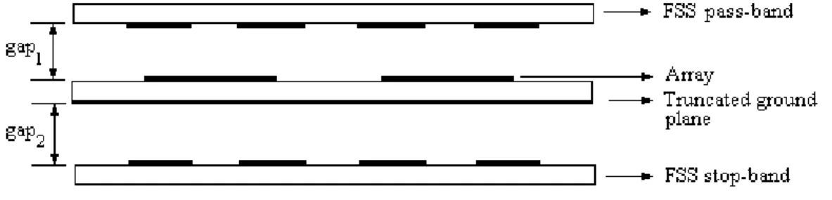
Trying to obtain a result even more significant, we used a third layout: The antenna array with
truncated ground plane, integrated with a stop-band FSS as ground plane and a band-pass FSS as superstrate. The idea is to reduce the surface waves and further improve the parameters of the array. Fig. 10 illustrates this configuration.
Fig. 10. Array with truncated ground plane integrated with stop band FSS, as ground plane, and with pass band FSS, as superstrate.
The best values for the gaps 1 and 2 were 1 cm and 3 cm, respectively. For this configuration, the bandwidth decreased to 672 MHz, at 2.45 GHz frequency the gain has been increased to 7.26 dBi , a half-power angle of 60o was kept in, the front-to-back ratio was increased to 17.33 dB and radiation
efficiency was around 85 %. For the 2.60 GHz frequency the gain was 7.67 dBi, the half power angle of 60o was kept in, the front-to-back ratio was 16.81 dB and radiation efficiency was around 80%. It
can be observed that the new configuration parameters remained close for the two frequency bands of desired applications. The reduction in efficiency is due to a not flat response of the FSS superstrate,
causing a larger insertion loss for the frequency of 2.60 GHz. Still, it can be seen that there was an improvement in the parameters of the previous configuration, although small decrease in bandwidth.
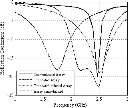
Fig. 11 illustrates the reflection coefficient for this layout, compared with the other configurations. The significant improvement in bandwidth allows this new array to be employed in two
applications, which are: WLAN and LTE 4G networks. The radiation diagrams in the E and H planes to the center frequencies of these two applications are illustrated in Fig. 12(a) and 12(b), these results
Fig. 11. Comparison of the reflection coefficient obtained for all proposed layouts.
(b)
Fig. 12. Radiation patterns for: (a) 2,45 GHz and (b) 2,60 GHz.
To illustrate how the band-pass FSS, used as a superstrate influences the array’s surface waves
distribution, graphs of the surface waves were obtained of all settings for the frequency of 2.45 GHz Fig, 13 illustrates the electric field distribution for the frequency 2.45 GHz in case of the conventional
array. We can observe an intense electric field in the region of the dielectric, which decreases the radiation efficiency of the array. For this case, the efficiency radiation is 52.8%. So, we can observe
high intensities of surface waves.
For the sandwiched array, it is observed that there is a visible reduction in the
concentration of the electric field in the vicinity of the array elements. This entails a greater
insulation between the elements of the array, as well as greater efficiency of radiation. Fig.
14(a) and 14(b) illustrate the surface waves of the electric field at frequencies of 2.45 GHz
and 2.60 GHz, respectively, for the case of the array with truncated ground plane between
two FSS. It can be observed a significant reduction in surface waves, compared with the
previous case.
(a)
(b)
Fig. 14. Electric field distribution for the array with truncated ground plane between two FSS, at frequency of: (a) 2.45 GHz and (b) 2.60 GHz.
between the results and we show that the array between FSS can be used in the deried
applications (WLAN and 4G).
Fig. 15. Measurement setup and built prototypes.
At the end of the study, the optimal array obtained is illustrated in Fig. 17. We can
observe a reduction in the dimensions of the patches which leads to a reduction in the
dimensions of the array as a whole.
(a)
(b)
V. CONCLUSIONS
The application of frequency selective surfaces in the antenna arrays proved to be a
good alternative when you want to modify radiation parameters of the array. It was found that
there is a better distance, for which this interaction between the FSS and the array provides
the best results. In this case, the values were 1 cm and 3 cm for the FSS superstrate and
ground plane, respectively. The parameters of the original array have been significantly
improved, in particular the bandwidth, gain and radiation efficiency. The new proposed
configuration can be used in panel directivity antennas for systems with central base station
sectorized cells in commercial applications of WLAN and 4G.
REFERENCES
[1] Islam, M. M., Islam, M. T., and Faruque, M. R. I., “Dual-Band Operation of a Microstrip Patch Antenna on a Duroid 5870 Substrate for Ku- and K-Bands,” The Scientific World Journal, pp. 1-10, 2013.
[2] Samsuzzaman, M., Islam, M. T., and Faruque, M. R. I., “Dual-band multi slot patch antenna for wireless applications," Journal of Telecommunications and Information Technology, vol. 2, pp. 19-23, 2013.
[3] Godara, L. C., Handbook of Antennas in Wireless Communications, CRC Press, New York, 2002. [4] Huang, Y. and Boyle, K., Antennas From Theory to Practice, John Wiley & Sons, New Jersey, 2008.
[5] Subbulakshmi, P. and Rajkumar, R., “Design and characterization of corporate feed rectangular microstrip patch array antenna”, International Conference on Emerging Trends in Computing, Communication and Nanotechnology (ICE-CCN), pp. 547 – 552, 2013. [6] Wolansky, D., Vsetula, P., Puskely, J. and Raida, Z., “Broadband small patch antenna array for Ka-band application”, 7th European
Conference on Antennas and Propagation (EuCAP), pp. 907 – 910, 2013.
[7] Hamoudi, H., Haddad, B. and Lognonne, P., “Study of a L2 patch antennas arrays for GNSS/GPS network”, 7th European Conference on Antennas and Propagation (EuCAP), pp. 2187 – 2191, 2013.
[8] Gruden, M., Jobs, M. and Rydberg, A., “Design and evaluation of conformal patch antenna array use with wireless sensor network inside jet engines”, 7th European Conference on Antennas and Propagation (EuCAP), pp. 2100 – 2102, 2013.
[9] Chahat, N., Zhadobov, M., Muhammad, S. A., Le Coq, L. and Sauleau, R., “60-GHz Textile Antenna Array for Body-Centric Communications”, IEEE Transactions on Antennas and Propagation, Vol. 61, pp. 1816 – 1824, 2013.
[10] Anguera, J., Montesinos, G., Puente, C., Borja, C., Soler, J. “An under-sampled high directivity microstrip patch array with a reduced number of radiating elements inspired on the Sierpinski fractal”, Microwave and Optical Technology Letters, Vol. 37, No. 2, pp. 100-103, 2003.
[11] Jayasinghe, J. M. J. W., Anguera, J. and Uduwawala, D. N., “Genetic algorithm optimization of a high-directivity microstrip patch antenna having a rectangular profile”, Radioengineering, Vol.22, No. 3, pp. 700 – 707, 2013.
[12] Kim, D., J. Yeo and J. Choi (2008), ‘Compact spatial triple-band-stop filter for cellular/PCS/IMT-2000 systems’, ETRI Journal. [13] Chaimool, S., Rakluea, C., and Akkaraekthalin, P., "Compact wideband microstrip thinned array antenna using EBG superstrate",
International Journal of Electronics and Communications (AEÜ), no. 66, pp. 49 – 56, 2012.
[14] Chen, Hsing-Yi (2010), ‘Bandwidth enhancement using dual-band frequency selective surface with Jerusalem cross elements for 2.4/5.8 GHz WLAN antennas’, IEEE International Conference on Wireless Information Technology and Systems, pp. 1-4.
[15] Yongxing, Che (2010), “Design of multiple FSS screens with dissimilar periodicities for directivity enhancement of a dual-band patch antenna”, International Symposium on Antennas Propagation and EM Theory, pp. 319-322.
[16] Ranga, Y., L. Matekovits, K. P. Esselle and A. R. Weily, “Enhanced gain UWB slot antenna with multilayer frequency selective surface reflector”, International Workshop on Antenna Technology, pp. 176-179, 2011.
[17] Wang, Y., Huang, J. and Feng, Z., "A Novel Fractal Multi0Band EBG Structure and Its Application in Multi0Antennas," IEEE Antennas and Propagation Society, International Symposium, pp. 5447 0 5450, 2007.
[18]
[19] Visser, H. J. (2005), Array and Phased Array Antenna Basics, John Wiley & Sons Ltd, England.