Fiabilitate si Durabilitate - Fiability & Durability No 2/ 2015
Editura “Academica Brâncuşi” , Târgu Jiu, ISSN 1844 – 640X 36
STRUCTURAL AND GEOMETRICAL ANALYSIS OF THE LIFTING
MANIPULATORS FOR A GREEN ENVIRONMENT
Ioana POPESCU, Iuliu Maniu Highschool, Bucharest, e-mail: [email protected] Dr. Ovidiu ANTONESCU, Univ. Politehnica of Bucharest, e-mail: [email protected]
Dr. Păun ANTONESCU, Univ. Politehnica of Bucharest, e-mail: [email protected]
Abstract: The lifting and getting off the bins, to and from the body of special waste trucks, by some
planar linkage – manipulators are studied. These lifting manipulators are equipped with gripper systems
in order to load and unload the bins. Several kinematical schemas of type mono– and bi-mobile
manipulators are analyzed, these being driven by one or two linear actuators. The kinematical geometry of these planar manipulators by means of scale drawing of the kinematical schema is displayed. Two solutions for a better efficiency and a green environment have been proposed. Finally, a modeling and simulation case of the lifting manipulator is presented.
Keywords: lifting manipulator, mobility, simulation
1. Introduction
The development of lifting manipulators for loading and unloading the waste freight into and from specialized trucks has not been treated so much in literature [2].
One of the best reference titles on bin lifting automotive history is “The photographic archive of waste trucks” by John B. Montville [4] that presents the development of garbage gathering vehicles since First World War to nowadays.
The first waste vehicles had an open top part of the body to collect the garbage though they were not specially designed to perform this task. By 1920 about twenty garbage trucks with closed carriage were accomplished in Great Britain. The advantage of this type was a bigger quantity of garbage that can be loaded in cleaner conditions into a greater carriage.
First truck carriage with outer bunker had been made in 1929 and the rear loading body with waste compactor in 1938. This principle of rear loading compactor carriage is the most used in present, even if at that time the waste bins were manually lifted and unloaded. Other models of waste trucks are with side (1947) or front (1955) loading.
2. Waste bins and loading mechanisms
Fiabilitate si Durabilitate - Fiability & Durability No 2/ 2015
Editura “Academica Brâncuşi” , Târgu Jiu, ISSN 1844 – 640X 37
Fig. 1. Waste loading process Fig. 2. Mechanical bin lifting
After the mechanical loading of the waste (fig. 2) from bin into the receiving bunker of truck, the garbage is pushed into the main compartment of carriage (fig. 1).
These bin lifting mechanisms (fig. 1) represent mono-mobile or bi-mobile manipulators [1] that grasp the bin, lift it until the receiving bunker level and lean it until the waste begin to fall into bunker. Ones the bin is rotated by over 90 degrees from initial position, the bin opens by itself maintaining the lid in vertical position (fig. 1 or 2) and the waste is unloaded.
3. Mono-mobile lifting manipulators
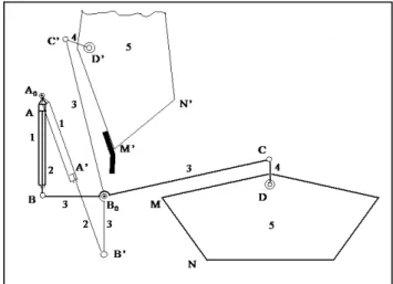
Let’s consider a mono-mobile lifting mechanism for heavy containers (fig. 3). This manipulator is a planar mechanism [1] that consists of one closed kinematical contour with hydraulic cylinder and another kinematical contour which is alternatively open in lifting phase or closed in waste unloading phase.
Fiabilitate si Durabilitate - Fiability & Durability No 2/ 2015
Editura “Academica Brâncuşi” , Târgu Jiu, ISSN 1844 – 640X 38
Initially, the rotate cylinder 1 of manipulator is in vertical position (thick line - fig. 3) having the piston 2 at top of it so that the rocker 3 has segment BB0 in horizontal position. Bar
4 is linked to the container 5 by a hook which allows an easy hanging of it and, also, a rotation of it in unloading phase (thin line - fig. 3).
In final position (thin line – fig. 3) the piston 2 is at bottom of cylinder 1 and the container 5 leans with point M (now M’) on a fixed point of carriage, the open kinematical chain formed of 3, 4 and 5 element becoming closed (B0C’ D’ M’).
In lifting phase the mechanism mobility results by using the following formula [1]:
5
1
6
2
m r
r
m rN
mC
M (1)
In this phase all six kinematical joints are mono-mobile (m = 1) and there is only one closed loop of rank 3 (r = 3), so that N3 = 1.
Therefore, by formula (1) results:M 16313
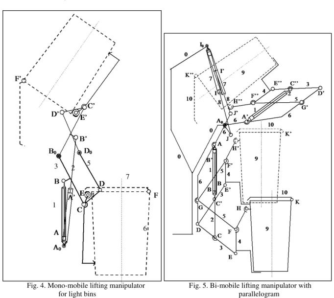
Fig. 4. Mono-mobile lifting manipulator Fig. 5. Bi-mobile lifting manipulator with for light bins parallelogram
1 2
3 5
4
Fiabilitate si Durabilitate - Fiability & Durability No 2/ 2015
Editura “Academica Brâncuşi” , Târgu Jiu, ISSN 1844 – 640X 39
Among these three mobilities (DOF) only one is active (controllable) – actuator (1+2). The others two mobilities are passive – rotation of bar 4 related to joint C and rotation of container 5 about joint D.
In the second phase there are two closed loops of rank 3, six joints of class 1 and one joint of class 2, resulting: M 1621322, but only one is active.
To manipulate light bins of plastic (dashed line – fig. 4) it is used a mono-mobile planar mechanism with two closed kinematical contours, the first one having the actuator as rotate cylinder and the second one being a rotate jointed quadrilateral (fig. 4).
The kinematical scheme of manipulator has been represented in two limit positions, the bottom one displayed with continuous thick line (initial position) and the top one with continuous thin line (final position). There are three fixed axes on the truck body A0, B0 and
D0. In the initial position (bin grasping) the cylinder 1 and piston 2 are in vertical position
with the minimum length A0B. Bar 4 has two mobile rotate joints C and D, and also the rotate
joint E by which the bin 6 is positioned.
In order to obtain the final position (waste unloading) the piston 2 slides into cylinder 1 to the end of stroke, the length A0B’ being maximum (fig. 4).
It can be observed that in initial position the rotate jointed quadrilateral B0CDD0 is
convex and in the final position it becomes concave (B0C’D’D0), the two rockers 3 and 5
being crossed. As it was mentioned in previous chapter, the bin 6 opens itself by maintaining the lid 7 in vertical position, this being linked to 6 by a rotate joint F’.
The mobility is checked by formula (1): M 17321
This type of mechanism (fig. 4) allows 130-145 degrees rotation of the bin, being the most used lifting manipulator in street salubrity.
Of course, these mono-mobile manipulators (fig. 3 and 4) are achieved as double mobile structures operating in parallel planes (on both carriage sides). Therefore, the two hydraulic actuators must be synchronized in order to lift the bin(s) properly. In the case of light bins, the manipulator lifts two or three plastic bins in the same time by using a horizontal bar (joint E in fig. 4) which links the two parallel mechanisms. On this connecting bar there are catching systems mounted, they being equipped with safety devices on manipulated bins.
4. Bi-mobile lifting manipulators
The bi-mobile lifting manipulators operate in the same conditions as mono-mobile ones, being double systems mounted in parallel planes, between them the waste bins being lifted and unloaded. The actuation of these mechanisms is provided by four hydraulic cylinders, each two of them in one working plane.
Fiabilitate si Durabilitate - Fiability & Durability No 2/ 2015
Editura “Academica Brâncuşi” , Târgu Jiu, ISSN 1844 – 640X 40
This bi-mobile mechanism (fig. 5) has the first mobility obtained by actuator (1+2) (linked to element 6 by rotate joint A and to element 3 by rotate joint C) and the second mobility obtained by actuator (7+8) (linked to truck body by rotate joint I0 and to element 6
by rotate joint J). The mobility is checked by formula (1): M 111332
In the first phase, when element 6 is static, the piston 2 slides into cylinder 1 until the stroke s21BB'CC' is complete. Therefore, the bar 4 (by which the bin 9 is sustained) executes a circular sliding reaching the vertical E’F’ position.
In the second phase, with the actuator (1+2) blocked (AB’C’), the actuator (7+8) begins to drive by sliding the piston 8 into cylinder 7 until the stroke is s87II'I0JI0J'. During this phase the element 6 rotates as a rigid body, together with elements 1, 2, 3, 4 (9) and 5, around the rotate joint A0 by 130 degrees.
As it was explained in the previous case the bin lid 10 remains in vertical position, allowing the waste to fall into the receiving bunker of truck.
After the bin is completely unloaded, the actuator (7+8) slides at maximum extended position I0J and then the actuator (1+2), once it reaches the vertical position, extends to
maximum stroke AC = s21max . Further, we consider a bi-mobile lifting manipulator with rotate
jointed quadrilateral (fig. 6). This may be called as general case comparing with the last one (fig. 5) because in the first phase the bin is lifted and rotated to about 45 degrees, and in the second phase it continues to rotate to extra 90 degrees.
The position of fixed rotate joint I0 of the second actuator lies under the fixed rotate joint
A0 on truck body. This is an advantage regarding the length of hydraulic actuator-supplying
pipes: closer actuators–shorter supplying tubes. In initial position of the first phase the kinematical schema (fig. 6) is drawn by continuous thick line (including the bin).
The actuator (1+2) by cylinder 1 is rotate jointed to the bar 6 (which is rotate jointed to carriage by fixed point A0) and by piston 2 to the rocker 3 which is also rotate jointed to the
bars 6 and 4. The bars 6, 3, 4 and 5 form a rotate jointed quadrilateral having “the base” 6 and 3 as driving element which is actuated by (1+2).
The kinematical schema (fig. 6) in the final position of the first phase is drawn by continuous thin line and the bin 9 by dashed thin line.
During this phase from DEFG position the quadrilateral gets to D’E’F’G’ position, where the bin 9 is rotated to about 45 degrees.
Fiabilitate si Durabilitate - Fiability & Durability No 2/ 2015
Editura “Academica Brâncuşi” , Târgu Jiu, ISSN 1844 – 640X 41
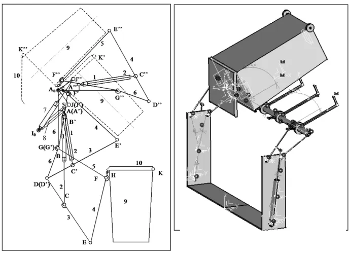
Fig. 6. Bi-mobile lifting manipulator with quadrilateral
Fig. 7. CAD modeling and kinematical simulation
Now, the actuator (7+8) takeovers the command, having the cylinder 7 rotate jointed in the fixed point I0 on truck body, and the piston 8 linked to element 6 in point J. The mobility
is checked by formula (1): M 111332. In the final position of second phase the manipulator is represented by continuous thin line (fig. 6) using the following notations: A”,
C”, D”, E”, F”, G” andK”. In this position the bin 9 is rotated to extra 90 degrees so that the bin lid 10 takes a vertical position allowing the waste to fall into receiving bunker.
5. Modeling and simulation of the lifting manipulator
Nowadays, by means of advanced CAD software systems, any component or mechanical assembly having a complex structure can be modeled and simulated. Designing a virtual entity, with precisely 3D dimensions (using three-dimensional space), requires a spatial vision and a detail-orientated eye. In order to simulate a process, we need that part to be as much as
7
Fiabilitate si Durabilitate - Fiability & Durability No 2/ 2015
Editura “Academica Brâncuşi” , Târgu Jiu, ISSN 1844 – 640X 42
possible like the real one. So, a virtual material with real properties can be applied to it. Thus, we can obtain a component which has its own characteristics that can be updated anytime.
The parametrical design has the advantage that by modifying a geometrical parameter of the component, all the other dimensions will be automatically changed in correlation with the given constrains.
Further, certain virtual assemblies, obtained by connecting their mobile mechanical elements, can be created, accomplishing mechanisms with one or more mobilities that can be animated and simulated on their operation as if they would have a real behavior.
Let’s consider the mono-mobile lifting manipulator with improved efficiency depicted in figure 7. The first step is the modeling of the main mechanical components such as the base 0 (truck body), the hydraulic cylinders 1 (including the pistons 2) as actuators, the T-rockers 3 linked to cylinder’s pistons, the rods 4 fixed to the transversal shaft (that connects the two parallel lifting mechanisms and sustains the two waste bins by special supports), the rockers 5, and the waste bins 6 (including their lids 7).
All these components of the lifting manipulator have been modeled by using a 2D sketcher. Then, the third dimension for each element, by using the 3D module, was created. Many other commands were used in order to shape the right configuration of them. The total number of parts (subcomponents) is 24.
Afterwards, these parts were assembled using a specific virtual workbench by adding the connection elements (such as shafts, pins and bearings) between them that, in fact, represent the rotate joints (fig. 7). The only sliding joints are between pistons and cylinders. It is necessary to be mentioned that before assembling the components, the accuracy of each part dimension has to be checked, so that the outcome should be a perfect combined product.
The 3D rendering of the lifting manipulator assembly can be achieved very easy just by computer mouse. The system can be rotated, moved or zoomed in/out by user in order to see the final product from any point of view.
For the kinematical joint applying between the mechanism’s components, the manipulator mobility has to be considered. This lifting mechanism having 1 DOF, the sliding range of the driving cylinders can be imposed so that the manipulator working space to be modeled, related to the necessity of a completely waste unloading from the bins.
The kinematical operating simulation of the lifting manipulator can be achieved by using the command panel by which the virtual displacement can be controlled.
6. Conclusions
Fiabilitate si Durabilitate - Fiability & Durability No 2/ 2015
Editura “Academica Brâncuşi” , Târgu Jiu, ISSN 1844 – 640X 43
References
1. Antonescu P., Antonescu O. Mechanism and Machine Dynamics (in Romanian). Printech Publishing House, Bucharest, 2005.
2. Voicu G., Paunescu I. Processes and Machines for City Cleaning, Matrix Press, Bucharest, 2002.
3. Coltofeanu R. Structural-Topological Analysis of the Lifting Mechanisms on Urban Salubrity Equipments. PhD Paperwork, Politehnica Univ. of Bucharest, 2005.
4. Antonescu, O., Coltofeanu, R., Antonescu, P., Geometria manipulatoarelor pentru descărcarea recipientelor cu reziduuri gunoiere, Rev.Mecanisme și Manipulatoare, Vol. 5, Nr. 2, 2006, pag. 25-30.
5. Geonea, I.,Coltofeanu, R., Motofeanu, S., Kinematics and dynamic modelling of a plane manipulator, Journal Mechanisms and Manipulators, Vol. 8, No 2, 2009, p. 41-46.