Evaluation of Subjective and Objective
Performance Metrics for Haptically Controlled
Robotic Systems
Cong Dung Pham
Huynh Nhat Trinh Phan
Pål Johan From
Department of Mathematical Sciences and Technology, Norwegian University of Life Sciences, 1432 Ås, Norway. E-mail: {coph, huph, pafr}@nmbu.no
Abstract
This paper studies in detail how different evaluation methods perform when it comes to describing the performance of haptically controlled mobile manipulators. Particularly, we investigate how well subjective metrics perform compared to objective metrics. To find the best metrics to describe the performance of a control scheme is challenging when human operators are involved; how the user perceives the performance of the controller does not necessarily correspond to the directly measurable metrics normally used in controller evaluation. It is therefore important to study whether there is any correspondence between how the user perceives the performance of a controller, and how it performs in terms of directly measurable metrics such as the time used to perform a task, number of errors, accuracy, and so on.
To perform these tests we choose a system that consists of a mobile manipulator that is controlled by an operator through a haptic device. This is a good system for studying different performance metrics as the performance can be determined by subjective metrics based on feedback from the users, and also as objective and directly measurable metrics. The system consists of a robotic arm which provides for interaction and manipulation, which is mounted on a mobile base which extends the workspace of the arm. The operator thus needs to perform both interaction and locomotion using a single haptic device. While the position of the on-board camera is determined by the base motion, the principal control objective is the motion of the manipulator arm. This calls for intelligent control allocation between the base and the manipulator arm in order to obtain intuitive control of both the camera and the arm. We implement three different approaches to the control allocation problem, i.e., whether the vehicle or manipulator arm actuation is applied to generate the desired motion. The performance of the different control schemes is evaluated, and our findings strongly suggest that objective metrics better describe the performance of the controller, even though there is a clear correlation between subjective and objective performance metrics. Keywords: Performance evaluation, controller design, human-robot interface, mobile manipulation
1 Introduction
Teleoperation and haptic control allow operators to control remotely located objects from a safe and com-fortable location. The main motivation for remotely operated robots is to relieve humans from entering
perceives the controller.
All teleoperated systems have one thing in common; they are controlled by a human operator, so how the human operator perceives the controller performance should thus be an important criterion when designing the controller. It is not straightforward, however, to find suitable metrics for this kind of subjective per-formance evaluations. In this paper we will use the NASA-TLX evaluation scheme to get feedback from the operators. In addition we will compare the results of the NASA-TLX with that of the objective metrics, which in this paper are i) the time used to perform a given task, ii) the number of errors/failures, and iii) the manipulability of the manipulator arm during the task. The main objective of comparing the subjective and objective metrics is to gain insight into to what extent these correlate. It is interesting to investigate whether or not the actual performance of the system is reflected in the feedback that we get from the operator. Human factor is an important part in human-robot interaction (HRI) (Goodrich and Schultz(2007)). NASA-TLX has been widely used to study operators performance and workload in HRI (Steinfeld et al.
(2006)). Measuring human mental workload when operators perform tasks with telerobotics, has been treated in for example Kiselev and Loutfi (2012),
Adams and Kaymaz-Keskinpala (2004), Kaber et al.
(2000a), and Stefanidis et al. (2010). Grane and Bengtsson(2005) compare how different types of inter-faces perform in terms of mental workload and Rook and Hogema(2005) used NASA-TLX to evaluate the effect of human-machine interface design. A relevant work on evaluating the HRI in vehicle navigation sys-tems has been studied inRoss and Burnett(2001), and
Kaber et al.(2000b) evaluate the effects of workload in a teleoperation task. Goodrich et al.(2004) proposed behavioral entropy as a technique to estimate human workload in HRI.
In this paper we use a haptically controlled mobile manipulator to perform the evaluation tests. The mo-bile manipulator allows for both locomotion and inter-action tasks, both of which are challenging tasks for the operator and require the controller to efficiently transmit information about the remote environment to the operator in order to perform the task. In addition to the manipulator arm the mobile robot is equipped with a camera that is fixed in one direction in the robot frame, so the operator will have a restricted amount of visual information about the environment.
Teleoperated robotic manipulators have long been an active field of research and a wide variety of controllers have been proposed. Passivity-based controllers are commonly used to control bilateral teleoperation sys-tems with two-port network representations (Hokayem
and Spong (2006), Ryu et al. (2004b), Ryu et al.
(2004a)). Energy-based approaches have also been pro-posed to obtain stable behavior of the two systems, for example in Hannaford (1989) and Franken et al.
(2011). Over the last years, however, we have seen an increased interest also in teleoperation of mobile ma-nipulators, i.e., a robotic manipulator mounted on a mobile base. This setup has great potential because it combines two important properties: the mobility of the mobile base and the dexterity and manipulability of the manipulator arm (Park and Khatib(2006), Ser-aji(1998),Farkhatdinov and Ryu(2008)).
We implement three different control schemes that cannot straightforwardly be separated in terms of per-formance and user evaluation, and find the correlation between the different performance metrics. As the con-trol is implemented on the slave side, the actual differ-ence between the approaches is rather subtle from the operator’s point of view, so good performance metrics are essential to be able to distinguish between them. The main objective is to investigate whether objec-tive and/or subjecobjec-tive metrics can distinguish between these control schemes, to find any correlation between the metrics, and to suggest a set of metrics that in a de-cisive way can quantify the performance of haptically controlled robotic systems.
2 System Setup and Problem
Formulation
The system to be studied consists of a standard bilat-eral teleoperation setup with a haptic device controlled by a human operator which is used to control a re-motely located robot. The robot consists of a wheeled vehicle with a manipulator arm attached to it. We will attach a frame Fb to the vehicle and denote the
loca-tion ofFb with respect to the inertial frameF0 by the
homogeneous matrixg0b and its velocity by the body
velocity twist ˆV0Bb =g−
1
0bg˙0b. The configuration of the
robotic arm is given by the joint variablesq∈Rnin the normal way, and the joint velocities as ˙q = ddqt ∈ R
n.
The position of the end-effector frameFe in the world
frame is found asg0e=g0bgbe(q) (From et al.(2010)).
We refer toFrom et al. (2014) for a detailed formula-tion of the kinematics of vehicle-manipulator systems.
2.1 The Control Allocation Problem for
Mobile Manipulators
Fb
F0
x y
z
x y z
Figure 1: The coordinates of a mobile manipulator with on-board camera
ii) locomotion of the vehicle in a possibly very large workspace. The main challenge is therefore to obtain a control allocation between the vehicle and the ma-nipulator in such a way that the motion of both the vehicle and the manipulator arm can be controlled in-tuitively using the manipulator-like haptic device. We denote this the control allocation problem for mobile manipulators.
The distribution of control forces between the ma-nipulator and the base to obtain both manipulation and locomotion is obtained through the control alloca-tion algorithm, i.e., how to interpret the master refer-ence (6 DoF) as both position and velocity referrefer-ences and how to distribute the control forces between the vehicle and the base (3+6 DoF), i.e., the control allo-cation problem for vehicle-manipulator systems.
In this paper we take the master reference and gen-erate position or velocity references for the vehicle and manipulator, and we denote this the control allocation problem because the motion is distributed between the two systems. It is important to note, however, that we assume that the low-level controllers of the vehi-cle and manipulators are such that these references are followed, i.e., we are only concerned with kinematic control. Once the control allocation is in place, any method for stable teleoperation can be used, such as passivity- and energy-based approaches.
2.2 Problem Formulation
The main motivation of this paper is to gain more in-sight into how well different metrics describe the
per-formance of user controlled mechanical systems. The main objective is to understand whether or not the way the user perceives the controller is reflected in the ac-tual behavior of the robot in terms of objective and directly measurable metrics. We study the correlation between
1. Objective performance metrics a) execution time
b) number of failures c) arm manipulability 2. Subjective performance metrics
a) NASA-TLX b) interview.
We will compare three control schemes with similar characteristics and endeavor to determine whether the objective or subjective metrics best describe the per-formance of the system, and in particular if they give the same result.
3 Motion Control
In this section, we will briefly introduce what we re-fer to as the control allocation problem for vehicle-manipulator systems, i.e., how a reference trajectory is allocated between the vehicle and the arm. This problem has been studied in detail inPham and From
(2013).
3.1 Control Modes
All of the approaches presented in this paper use the notion of control modes to determine distribution of control forces. The control modes are described in brief below.
3.1.1 Manipulation Mode
3.1.2 Locomotion Mode
Whenever a large displacement of the robot is needed the vehicle needs to take care of this motion. Normally a position-to-velocity control scheme is chosen to allow for an infinitely large slave workspace. In locomotion mode the vehicle and the arm are used to obtain large displacements of the end-effector. As the master robot is to control both the vehicle and the slave arm, we have two kinematically dissimilar systems. We solve this by virtually connecting the master end effector to the slave end effector, which is our primary control objective.
3.2 Control Strategies
In this section we present in brief the three control strategies used for the experiments in this paper. We refer to Pham and From (2013) for a more detailed description of the control laws.
3.2.1 Strategy I - Master workspace strategy
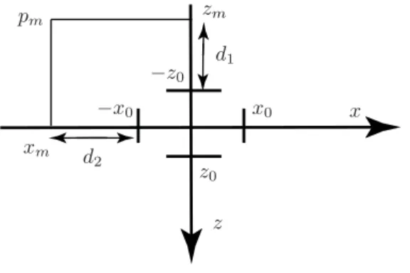
With this strategy, the robot will automatically change between the two control modes depending on the mas-ter position. If the robot is far from the goal, the op-erator will move the haptic device far and fast. It is thus natural to define a limit area in the master ma-nipulator’s workspace so that whenever the master is inside this area, the robot will be controlled in manipu-lation mode while we switch to locomotion mode when it moves out of the area. Using the limits as defined in Figure 2 the mode is chosen corresponding to the following law:
Mode =
Manipulation if
|zm| ≤z0
|xm| ≤x0
|vz| ≤v0
Locomotion otherwise
(1)
where zm and xm are the master positions in the
zx-plane of the haptic device andvz is the master speed
in the z-axis of the master frame. z0, x0 and v0 are
constant parameters that define when switching will occur.
When in locomotion mode we allow only for motion of the vehicle which is given by
vs
φs
=
−kv 0
0 −kφ
d1
d2
(2) wherekv andkφ are proportionality constants;vsand
φsare the velocity and the heading angle of the vehicle
in the body frame; and d1 and d2 are defined by the
position of the haptic device, as shown in Figure2, i.e., the distances from the master’s tip position to the limit area that is used to define the manipulation mode.
xm
zm
x0 −x0
−z0
z0 d2
pm
d1
x
z
Figure 2: Determining d1 and d2 from the haptic
position.
3.2.2 Strategy II - Slave workspace strategy
Alternatively we can use the slave workspace to de-termine the control mode. Like in Wrock and Nok-leby(2011), the system changes automatically from the manipulation mode to the locomotion mode when the slave manipulator reaches the limit of the workspace. We thus have
Mode =
Locomotion if
|xs| ≥xlor|ys| ≥yl |xsd| ≥xl
|ysd| ≥yl
Manipulation otherwise
wherexsandysare the actual slave positions in the
x-and y- axes of the robot frame;xsd and ysd, that are
computed from actual master positions, are the desired slave manipulator position; andxlandyl are the slave
limit positions in thex- andy- axes of the robot frame, respectively. The locomotion mode using this approach is similar to the master workspace strategy presented in3.2.1.
3.2.3 Strategy III - Control Allocation
In this section we describe the third control scheme, first presented inPham and From(2013), which intro-duces artificial forces between the end-effector and the base.
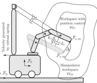
First we find the manipulator workspace WM with
respect to the vehicle frame Fb. We define the
workspace for position control as a workspace WP,
somewhat smaller than the manipulator workspace
WM, as illustrated in Figure 3. Whenever the
ma-nipulator is inside this workspace, position control is applied. This is equivalent to the manipulation mode in the previous sections.
If the master manipulator is outside the workspace
WP, velocity control is applied. In this case the
workspace, while the vehicle velocity is so that the vehi-cle follows the master end-effector with a mass-spring-damper characteristics.
Denote by ¯xs the position of the end effector
pro-jected into the position workspace WP, as illustrated
in Figure 3. Then the slave position with respect to this projected position is given by ∆ =xs−x¯sand we
will let the vehicle be governed by
F = ¨∆ +d∆ +˙ k∆. (3) The following references will give the above character-istics:
• Manipulator arm reference:
V0Be,r=V B
0e,d−
1 db
F, (4)
• Vehicle reference:
V0Bb,r=
1 db
F. (5)
This control law is to be interpreted in the following way: The desired end-effector velocity in the inertial space is given byVB
0e,d. The manipulator reference is
obtained by the Adjoint map Adg(From et al.(2014))
and subtracting the vehicle motionVB
0b,r, i.e.,
Vbe,rB =V0Be,d−AdgebV B
0b,r (6)
so it only remains to find the reference for the vehi-cle motion from the desired end-effector motion. The position, velocity, and acceleration of the end effector with respect to the vehicle generates a forceFgiven by eq. (3) that acts on the vehicle. This force is transferred into a vehicle motion, or rather the vehicle velocity by eq. (5) wheredb can be interpreted as the damping on
the vehicle. Note that this is different fromdwhich is the desired damping characteristics as observed from the camera when watching the end effector. Finally the motion of the vehicle is removed from the desired motion passed on to the manipulator controller. Note also that the constants in the mass-spring-damper sys-tem (3) need to be tuned to avoid saturation in the manipulator workspace.
For a wheeled robot no instantaneous motion in the direction of the y-axis is allowed, in which case the torques that act on the vehicle will take the form
τV =
m∆¨x+d∆˙x+k∆x
0
m∆¨y,ψ+d∆˙y,ψ+k∆y,ψ
. (7)
F0
Fb
∆ kv
dv
¯ Fe,m
V
e
lo
cit
y
generated
b
y
virtual
spring
Fe,m
Workspace with position control
WP
Manipulator workspace
WM
Figure 3: Definition of the workspaces in which the robot is controlled in the locomotion and ma-nipulation modes. Note that the workspace is defined for the manipulator arm with re-spect to the vehicle frame Fb, and not the
world frame F0. The velocity is generated
by the virtual spring between the master manipulator (gray) and the slave manipu-lator (black). The intuitive interpretation of the virtual spring is illustrated by the spring between the master manipulator and the vehicle.
4 Experiments—Rationale and
Methods
Several inexperienced operators were asked to control the robot to perform a simple task which required both fine manipulation and locomotion. Even though the task itself is simple, it is hard to perform because the operator only sees the remote workspace through a nar-row camera window. It is further complicated by the kinematic dissimilarity of the master and the slave.
same result.
We perform a series of experiments and measure the performance using both a subjective workload assess-ment and measurable metric values to characterize the performance of the control laws. For the subjective evaluation we use the NASA-TLX test which gives us an overall workload score calculated from the weighted average of six subcategories. This will give us an idea of how mentally challenging the operators find the task. The objective evaluation of the task is performed based on execution time, number of failures, and the mobil-ity of the robot arm during task execution. Our main objective is to discover discrepancies between the ap-proaches and, if such a discrepancy exists, evaluate what is the best way to evaluate the performance of an interaction task using a mobile manipulator.
4.1 Robotic Setup
A standard 6-DoF Phantom haptic device from Sens-able was used to control a mobile manipulator con-sisting of a Pioneer 3-AT mobile robot with a 7-DoF Cyton arm attached to it. The local computer commu-nicates with the remotely located on-board computer via a wireless network. The time delay is minimal and not treated in this paper. The control is, however, implemented so that it is robust with respect to time delays.
The operator’s view of the remote workspace is through a video image displayed on a screen only, i.e., there is no direct visual of the robot. The video is captured by a camera and transmitted to a screen.
4.2 Methods
The participants were asked to conduct a specific task which consisted in traversing a room to pick up an object and put it into a bin. We also placed several obstacles between the starting point and the destina-tion to enforce a change of direcdestina-tion during the loco-motion. The operators have to control the robot to cross the room and avoid all obstacles to complete the task. When they arrive at the final destination they have to pick up an object and place it into the bin, which completes the task. The task is constructed to force switching between the two control modes.
To verify the control scheme presented we let several inexperienced operators control the robot. We let the operators perform several different tasks using three different strategies:
S1. Automatic changing between locomotion and ma-nipulation mode using master workspace, Section 3.2.1;
S2. Automatic changing between locomotion and ma-nipulation mode using slave workspace, Section 3.2.2;
S3. Control allocation approach, Section 3.2.3. To avoid learning effects the sequence of the control schemes is randomized:
• 1/3 of the operators perform the experiments with the sequence of the control schemes S1-S2-S3
• 1/3 of the operators perform the experiments with the sequence of the control schemes S2-S3-S1
• 1/3 of the operators perform the experiments with the sequence of the control schemes S3-S1-S2 To evaluate the performance of the operators the following metrics were used:
Subjective metrics
The following subjective metrics were used:
• Interview -the operators were asked to describe how each control law performed.
• NASA-TLX - the operators filled in the NASA Task Load Index (NASA-TLX). The NASA-TLX uses six dimensions to assess mental workload: mental demand, physical demand, temporal de-mand, performance, effort, and frustration (Rubio et al.,2004). After performing each task, the oper-ators provide ratings on each of the six subscales. The operator is also asked to rate which factors he/she considers the most important.
Objective metrics
The following objective metrics were used:
• Number of failures - the number of failures for each approach was registered.
• Execution time - the time needed to complete the task (when successful) was recorded.
5 Experimental Results and
Discussion
In this section we first present the experimental results in Section5.1, followed by a discussion in Section5.2.
5.1 Experimental Results
5.1.1 General Feedback
All the operators were interviewed during and after the experiments which gave valuable feedback regard-ing their "feel" durregard-ing the experiments. This is im-portant information when we later are to evaluate the teleoperation schemes and compare them.
For the master workspace strategy, almost all oper-ators are confused whether it is the vehicle or the arm that is controlled. The reason for this is probably that the arm (which is visible for the operator on the screen) does not follow the master, i.e., it can stop moving as the master enters the locomotion mode. The operators report that this makes it difficult to control the system. With the slave workspace, on the other hand, the operators know exactly when the vehicle will move be-cause the arm has to move to the limit before the vehicle can move. They therefore report that they can perform the task more easily. However, since this is a rather simpletask—just to grasp an object— they almost only use the locomotion mode. The slave workspace strategy allows for this as the manipulator arm is stretched forward during locomotion mode. The master workspace strategy, on the other hand, does not necessarily allow for this as the arm may be re-tracted during locomotion mode. In principle the op-erators have to control the robot so that the end effec-tor passes the object and then move the arm back to grasp the object. Because the arm is at the limit of its workspace when the system moves towards the object, some operators find it difficult to position the system close enough to the object. This motivates leaving the manipulator more in the middle of its workspace during locomotion mode.
The operators report that the control allocation ap-proach is the most intuitive and find it fairly simple once they manage to think of the task as controlling the end-effector motion. They also report that they are able to disregard the vehicle motion when perform-ing manipulation tasks and also when the vehicle is moving slowly. This makes the operation more effi-cient because the switching is hidden from the opera-tor. With this approach, the operator can easily drive the system close enough to the object to execute the task. At this position, the arm is close to the center of its workspace so that it can be controlled in the ma-nipulation mode. This strategy thus takes advantage of
the slave workspace strategy and also eliminates some of the drawbacks of the same strategy.
5.1.2 Quantitative Metrics
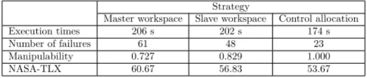
To get a more quantitative evaluation of the different approaches we measured the median execution times, number of failures, and median manipulability for each operator performing the task. We also asked the op-erators to fill in the NASA-TLX form. A summary of
the results is shown in Table1.
Strategy
Master workspace Slave workspace Control allocation Execution times 206 s 202 s 174 s
Number of failures 61 48 23
Manipulability 0.727 0.829 1.000
NASA-TLX 60.67 56.83 53.67
Table 1: Median execution times, number of failures, median manipulability (normalized), and me-dian NASA-TLX for the three strategies for 24 inexperienced operators.
The executing times of the 24 operators are shown in
Figure4and Figure5. We see that the control
alloca-tion is the approach that performs the best quite con-sistently. There are three operators that perform the operation fastest with the master workspace strategy and one user who takes the shortest time with the slave
workspace strategy. Figure5shows the overall
perfor-mance in terms of execution times and we see that the control allocation has better performance. This con-firms the feedback from the operators that the third method is the most intuitive.
The number of failures for the three strategies is
shown in Figure6 and Figure7. The highest number
of failures occurs for the master strategy. This corre-sponds well with the operators’ "feel"; they reported that they felt confused when they control the robot using this strategy because the robot can change quite suddenly between the two control modes when the mas-ter moves in or out of the limit area, which can cause failures. Also the slave strategy has a high number of fail tries. Recall that the slave manipulator is at the limit of its workspace (stretched out) when the robot moves towards the object so that it is difficult for op-erators to put the robot in a good position to interact with the object. The control allocation strategy has the lowest number of failures. Also this is natural as the manipulator arm is drawn towards the center of its workspace and also corresponds well with the feedback from the operators.
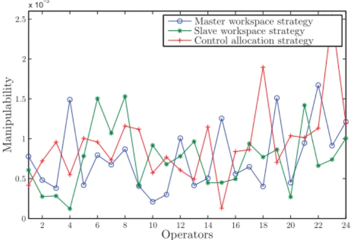
For the manipulability metric the control allocation maintains good manipulability during the grasping
Master workspace strategy Slave workspace strategy Control allocation strategy
Operators
Seconds
120 140 160 180 200 220 240 260 280 300
2 4 6 8 10 12 14 16 18 20 22 24
Figure 4: The executing times for 24 inexperienced op-erators performing the three strategies
Seconds
Master Workspace Slave Workspace Control Allocation
100 150 200 250 300
Figure 5: The median, the maximum, 75th percentile, 25th percentile and minimum values of exe-cuting times.
The control allocation maintains its high manipulabil-ity due to the virtual spring. The master workspace has a little bit better manipulability than the slave workspace. We will not put too much into this, how-ever, as the positioning of the arm for the master workspace approach is random. The slave workspace strategy has the lowest manipulability because the slave manipulator is normally fixed at the limit of the workspace when in locomotion mode, which is the main drawback of this strategy.
Also for the NASA-TLX the control allocation per-forms slightly better than the other approaches, as can
be seen from Table1, Figure10and Figure 11. Once
again the control allocation strategy has the best per-formance with a slight advantage over the other ap-proaches. There are some minor variations in perfor-mance for the different subcategories, for example the operators clearly feel a higher level of frustration when using the slave and master workspace strategy
com-Master workspace strategy Slave workspace strategy Control allocation strategy
Operators
Num
b
er
of
failures
0 1 2
2 3 4
4 5
6 8 10 12 14 16 18 20 22 24
Figure 6: The number of failures for 24 inexperienced operators performing the three strategies
Num
b
er
of
failures
Master Workspace Slave Workspace Control Allocation
0 1 2 3 4 5
Figure 7: The median, the maximum, 75th percentile, 25th percentile and minimum values of num-ber of failures.
pared to the control allocation, while they feel more stress on temporal demand with the control allocation.
5.2 Discussion
Several different metrics for evaluating the perfor-mance of the proposed control schemes were presented. We divide the metrics into theoretical and directly measurable performance metrics on one hand, and sub-jective metrics such as stress and frustration on the other. The main purpose of this paper is to evaluate whether objective or subjective performance metrics best describe the performance of a control law for tele-operation of mobile manipulators with limited visual feedback from the remote environment, and whether there is any discrepancy between the approaches.
experi-x 10−3
Master workspace strategy Slave workspace strategy Control allocation strategy
Operators
Manipulabilit
y
0 0.5 1.5 2.5
1 2
2 4 6 8 10 12 14 16 18 20 22 24
Figure 8: The manipulability in three strategy of 24 inexperienced operators
Master Workspace Slave Workspace Control Allocation
0 0.0005 0.001 0.0015 0.002 0.0025
Figure 9: The median, the maximum, 75th percentile, 25th percentile and minimum values of manipulability.
ments performed was quite low. It is fair to conclude from this that the number of experiments performed is sufficient to distinguish between the different control approaches.
The experiments suggest that the operator actually has a fairly good intuition when it comes to what con-trol scheme that performs the best, which is not ob-vious as the operator only has limited knowledge of what happens on the slave side. In fact, we get more useful information from the interview process than the NASA-TLX. While the operator certainly has a good notion of how well he does in terms of failures, the execution times are in many cases very similar and it is probably fair to say that the operator will not give much thought to the manipulability during the oper-ation. It is therefore not obvious that these results are mirrored in the interview process and the NASA-TLX. On the other hand, we believe that the theoreti-cal metrics such as number of failures, execution time,
Scores
Master Workspace Slave Workspace Control Allocation
25 35 45 55 65 75
Figure 10: The median, the maximum, 75th percentile, 25th percentile and minimum values of NASA TLX scores.
Scores Master Workspace
Slave Workspace
Control Allocation
Men tal
Demand
Physical Demand
Temp oral
Demand Perf
orm
ance Effort
Frus trat
ion
0 50 100 150 200 250
Figure 11: Six different categories evaluated in measur-ing workload
and manipulability give a better measure of the actual performance; the number of failures, for example, tells us that the control allocation approach clearly outper-forms the other methods, but this is not clear from the NASA-TLX test. We see that there is a clear corre-spondence between the general feedback and the ob-jective metrics, but this is only partially seen from the results of the NASA-TLX test.
6 Conclusion
In this paper we have compared subjective and ob-jective performance metrics for evaluating the perfor-mance of different controllers for mechanical systems that are haptically controlled by human operators. We find that even though subjective metrics based on the NASA-TLX and interviews give a fair indication of the performance of a control scheme, the objective and di-rectly measurable evaluation methods represent bet-ter metrics of performance evaluation. In fact we find that objective metrics such as execution time, number of failures, and arm manipulability correspond better with the feedback during the interview than the NASA-TLX, which may come as a surprise, as the intention of the NASA-TLX is to capture the mental workload during operation. Even though the feedback from the operators is important to get a good understanding of how a controller performs, the results strongly suggest that objective metrics do better when it comes to eval-uating the performance of different control schemes of systems controlled by a human operator.
References
Adams, J. and Kaymaz-Keskinpala, H. Analysis of perceived workload when using a pda for mobile
robot teleoperation. In Proceedings of IEEE
In-ternational Conference on Robotics and
Automa-tion, volume 4. pages 4128–4133 Vol.4, 2004.
doi:10.1109/ROBOT.2004.1308919.
Farkhatdinov, I. and Ryu, J. H. Switching of
control signals in teleoperation systems:
Formal-ization and application. In Advanced Intelligent
Mechatronics, 2008. AIM 2008. IEEE/ASME In-ternational Conference on. pages 353–358, 2008. doi:10.1109/AIM.2008.4601686.
Franken, M., Stramigioli, S., Misra, S., Secchi,
C., and Macchelli, A. Bilateral
telemanipula-tion with time delays: A two-layer approach
combining passivity and transparency. Robotics,
IEEE Transactions on, 2011. 27(4):741–756.
doi:10.1109/TRO.2011.2142430.
From, P. J., Duindam, V., Pettersen, K. Y., Gravdahl, J. T., and Sastry, S. Singularity-free dynamic
equa-tions of vehicle-manipulator systems. Simulation
Modelling Practice and Theory, 2010. 18(6):712–731.
From, P. J., Pettersen, K. Y., and Gravdahl., J. T.
Vehicle-manipulator systems - modeling for simula-tion, analysis, and control. Springer Verlag, London,
UK, 2014.
Goodrich, M. A., Boer, E. R., Crandall, J. W., Ricks, R. W., and Quigley, M. L. Behavioral entropy in human-robot interaction. Technical report, DTIC Document, 2004.
Goodrich, M. A. and Schultz, A. C. Human-robot
interaction: a survey. Foundations and trends in
human-computer interaction, 2007. 1(3):203–275.
Grane, C. and Bengtsson, P. Menu selection with a ro-tary device founded on haptic and/or graphic
infor-mation. InEurohaptics Conference, 2005 and
Sym-posium on Haptic Interfaces for Virtual Environ-ment and Teleoperator Systems, 2005. World Hap-tics 2005. First Joint. pages 475–476, 2005.
Hannaford, B. A design framework for teleoperators
with kinesthetic feedback. Robotics and
Automa-tion, IEEE Transactions on, 1989. 5(4):426–434. doi:10.1109/70.88057.
Hokayem, P. F. and Spong, M. W.
Bi-lateral teleoperation: An historical
sur-vey. Automatica, 2006. 42(12):2035–2057.
doi:10.1016/j.automatica.2006.06.027.
Kaber, D. B., Onal, E., and Endsley, M. R. Design of automation for telerobots and the effect on perfor-mance, operator situation awareness, and subjective
workload. Human Factors and Ergonomics in
Man-ufacturing, 2000a. 10(4):409–430. doi:
10.1002/1520-6564(200023)10:4<409::AID-HFM4>3.0.CO;2-V.
Kaber, D. B., Riley, J. M., Zhou, R., and Draper, J. Ef-fects of visual interface design, and control mode and latency on performance, telepresence and workload
in a teleoperation task. In Proceedings of the
Hu-man Factors and Ergonomics Society Annual
Meet-ing, volume 44. SAGE Publications, pages 503–506,
2000b.
Kiselev, A. and Loutfi, A. Using a mental workload index as a measure of usability of a user interface for
social robotic telepresence. In Workshop in Social
Robotics Telepresence. 2012.
Park, J. and Khatib, O. Robust haptic teleoperation of a mobile manipulation platform. 2006.
Pham, C. D. and From, P. J. Control allocation for mobile manipulators with on-board cameras. In
IEEE/RSJ International Conference on Intelligent Robots and Systems (IROS). pages 5002–5008, 2013.
doi:10.1109/IROS.2013.6697079.
driving behavior and acceptance.Transportation search Record: Journal of the Transportation Re-search Board, 2005. 1937(-1):79–86.
Ross, T. and Burnett, G. Evaluating the humanŰ-machine interface to vehicle navigation systems as
an example of ubiquitous computing.
Interna-tional Journal of Human-Computer Studies, 2001.
55(4):661 – 674. doi:10.1006/ijhc.2001.0495.
Rubio, S., Diaz, E., Martin, J., and Puente, J. M. Evaluation of subjective mental workload: A com-parison of swat, nasa-tlx, and workload profile
methods. Applied Psychology, 2004. 53(1):61–86.
doi:10.1111/j.1464-0597.2004.00161.x.
Ryu, J. H., Kim, Y. S., and Hannaford, B. Sampled- and continuous-time passivity and
stability of virtual environments. Robotics,
IEEE Transactions on, 2004a. 20(4):772–776.
doi:10.1109/TRO.2004.829453.
Ryu, J. H., Kwon, D. S., and Hannaford, B.
Stable teleoperation with time-domain
pas-sivity control. Robotics and Automation,
IEEE Transactions on, 2004b. 20(2):365–373.
doi:10.1109/TRA.2004.824689.
Seraji, H. A unified approach to motion
con-trol of mobile manipulators. International
Jour-nal of Robotics Research, 1998. 17(2):107–118.
doi:10.1177/027836499801700201. Seraji, H.
Stefanidis, D., Wang, F., Korndorffer Jr, J. R., Dunne, J. B., and Scott, D. J. Robotic assistance improves intracorporeal suturing performance and safety in the operating room while decreasing operator
work-load. Surgical endoscopy, 2010. 24(2):377–382.
doi:10.1007/s00464-009-0578-0.
Steinfeld, A., Fong, T., Kaber, D., Lewis, M., Scholtz, J., Schultz, A., and Goodrich, M. Common metrics
for human-robot interaction. In Proceedings of the
1st ACM SIGCHI/SIGART conference on Human-robot interaction. ACM, pages 33–40, 2006.
Wrock, M. R. and Nokleby, S. B. Decoupled teleop-eration of a holonomic mobile-manipulator system
using automatic switching. In Electrical and