American Journal of Engineering Research (AJER)
e-ISSN : 2320-0847 p-ISSN : 2320-0936
Volume-02, Issue-08, pp-12-23
www.ajer.org
Research Paper Open Access
GAPOD and GA DC-voltage regulator based UPFC supplementary cont
roller for damping low frequency oscillations in Multi-machine power
systems
Dakka. Obulesu, Dr. S.F. Kodad, Dr. B.V. Sankar Ram
1(Asso Professor, Department of Electrical & Electronics Engg., VEMU.I.T. P.Kothakota, Chittoor dist, Andhra Pradesh-517325,India)
2
(Principal, Krishna Murthy Institute of Technology and Engineering, Hyderabad, India.) 3
(Director, Admissions, J.N.T.U.C, Hyderabad, India.)
Abstract: - The Unified Power Flow Controller (UPFC) is the most versatile device in the FACTS (Flexible AC Transmission Systems) which has emerged to enhance power system stability spectrum and dynamic performance. This paper briefs the effectiveness of the proposed GAPOD and GA DC-voltage regulator which has been tested on a 3-Machine, 9-Bus power system in comparison with Particle swarm optimization based Multi-Stage Fuzzy (PSOMSF) DC-voltage regulator. The non-linear time-domain simulation results show that the oscillations of synchronous machines could be quickly and effectively damped with proposed GAPOD and GA DC-voltage regulator. The construction and implementation of this controller is fairly easy, which can be useful in real world power system.
Keywords: - FACTS, UPFC, GAPOD (Genetic Algorithms based Power oscillation damping) controller, PSOMSF, low frequency oscillations.
I. INTRODUCTION
The present day interconnected power system comprises of a large number of generators being connected together through a high-voltage long transmission network, supplying power to loads through lower-voltage distribution. Day by day the electric power demand on the utilities is increasing due to the rapid
urbanization and over growing population. Today‟s power system is thus much more loaded than before and
operating near their stability limits and expansion in transmission and generation is restricted with the limited availability of resources and the environmental conditions. According to IEEE, FACTS - which is the abbreviation of Flexible AC Transmission Systems, is defined as “alternating current transmission systems incorporating power electronics based and other static controllers to enhance controllability and power transfer
capability”. Dynamic reactive power compensation and damping power system oscillations can also be achieved using FACTS controllers. Injecting the series voltage phasor, with desirable voltage magnitude and phase angle in a line can provide a powerful means of precisely controlling the active and reactive power flows, by which system stability can be improved, system reliability can be enhanced while operating and transmission investment cost can be reduced. It is possible to vary the impedance of specific transmission line to force power
flow along a desired “contract path” in the emerging power systems, and to regulate the unwanted loop power
flows and parallel power flows in the interconnected system. The FACTS controllers have been broadly developed on two different principles, one that alters the line series reactance or bus shunt reactance or voltage phase difference across a line and utilizes conventional thyristor switches for control. In general, FACTS controllers can be divided into four categories based on their connection in the network, viz., series, shunt, combined series-series, and combined series-shunt. In our work, we have used the series-shunt combination [2].
with these objectives. Gyugyi proposed the Unified Power Flow Controller which is the new type generation of FACTS devices in the year 1991 [5]. Unified Power Flow Controller (UPFC), being one the member of the FACTS device thus emerged as one of the effective controllers for controlling and optimization of the power flow in the electrical power transmission systems [7]. This device was formed due to the combination of the two other FACTS devices, namely Static Synchronous Compensator (STATCOM) and the Static Synchronous Series Compensator (SSSC). These are connected to each other by a common DC link, which is a typical a storage capacitor. The all parameters of the power transmission line (impedance, voltage and phase angle) can be control simultaneously by UPFC [6,8]. In the modern day power system stability, operation & control (PSOC), FACTS (Flexible AC Transmission Systems) plays a very important role. Usage of FACTS in the power systems not only enhances the dynamic performance, but also increases the stability of the power systems, enhances the controllability and increases its power transfer capability. Some of the devices used in the control of FACTS are the SVC, TCSC, STATCOM, UPFC, and the IPFC [1]. The FACTS controllers utilize power electronics based technology and can provide dynamic control on line power flows, bus voltages, line impedance & phase angles. One of the controllers being used in the work presented in this paper is the GAPOD and GA DC- voltage regulator scheme for the damping of power system oscillations. The FACTS initiative was originally launched in 1980‟s to solve the emerging problems faced due to restrictions on transmission line construction, and to facilitate growing power export/import and wheeling transactions among utilities. The two basic objectives behind the development of FACTS technology; is to increase power transfer capability of transmission systems, and to keep power flow over designated routes, significantly increase the utilization of existing (and new) transmission assets, and play a major role in facilitating contractual power flow in electricity markets with minimal requirements for new transmission lines. FACTS devices have shown very promising results when used to improve the power system steady state performance. In addition, because of the extremely fast control action associated with FACTS-device operations, they have been very promising candidates for utilization in power system damping enhancement. The first generation FACTS devices include SVC, TCPS, and TCSC. It has been found that SVCs can be effective in damping power system oscillations if a supplementary feedback signal is applied [9-10]. Compared with other FACTS devices, little attention has been paid to TCPS modeling and control. Based on the equal area criterion, the TCPS control problem has also investigated using linear control techniques [11-13]. Many research efforts have been devoted to the control of TCSC. Chen et. al. designed a state feedback TCSC controller based on the pole placement technique [14]. Other TCSC optimal and nonlinear control schemes proposed in the literature [15-17]. A unified power flow controller (UPFC) is the most promising device in the FACTS concept. Several trials have been reported in the literature to model a UPFC for steady-state and transient studies. Based on Nabavi-Iravani model [18], Wang developed two UPFC models which have been linearized and incorporated into the Heffron-Phillips model [3].
II. MULTI-MACHINESYSTEMWITHUPFC
In Fig(1), the generators and the line with UPFC are shown to be connected to the network with the bus admittance[Yt].
The four input control signals to the UPFC are mE, mB, E, and B where mE is the excitation amplitude modulation ration, mB is the boosting amplitude modulation ratio, E is the excitation phase angle and Bis the boosting phase angle. The UPFC is installed for the purpose of multiple control functions, one of which will be the suppression of low-frequency oscillations occurring in the system. Various feedback signals namely, deviation in generator rotor angle, deviations in real power flow through the transmission line, accelerating power, have been identified as capable of contributing direct electric damping torque to the electromechanical oscillation loop of the generator. A wise selection of the feedback signal can be done based on its capability in improving the damping of desired mode of oscillation.
II.A PSO based MSF (PSOMSF) controllers for UPFC
Structure of a PSO based Multi-Stage Fuzzy control strategy are shown in fig.2. In this structure, input values are converted to truth-value vectors and applied to their respective rule base.
Ki / S Fuzzify I
Fuzzify P PD
Rule Base
PID Switch
Rule Base Defuzzify
Fuzzify D
1 / S
ΔVdc
Delta
PSO
K2
If delta < 70o then Pass up path
else down path
δ
K1
+
PSO Multi – Stage Fuzzy Controller Multi – Stage Fuzzy Controller
Fig.2. Structure of a PSO based Multi-Stage Fuzzy control strategy
Table.1 PD rule base
e
NB NM NS ZO PS PM PB
dc
e
V
NB NB NB NB NB NM NS ZO NM NB NB NB NM NS ZO PS NS NB NB NM NS ZO PS PM ZO NB NM NS ZO PS PM PB PS NM NS ZO PS PM PB PB PM NS ZO PS PM PB PB PB PB ZO PS PM PB PB PB PB
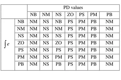
Table .2 PID switch rule base
PD values
NB NM NS ZO PS PM PB
e
NB NM NS NB PS PM PB NM NM NM NS NM PS PM PB NM NS NM NS NS PS PM PB NM ZO NM NS ZO PS PM PB NM PS NM NS PS PS PM PB NM PM NM NS PM PS PM PB NM PB NM NS PB PS PM PB NM
II.B POD controller design using genetic algorithm
The damping function of FACTS devices is preformed mainly through the changes of the power delivered along the transmission line. With appropriate lead-lag compensation, the damping torque provided by FACTS damping control is proportional to gain of the controller. Since FACTS devices are located in transmission systems away from generating stations, local availability of the feedback signal is of a major concern. Thus, the selection of feedback signal is done on the basis of availability of the signal locally. Another concern is choosing the proper candidate feedback signal is its effectiveness in damping the desired mode of oscillations. Residue method is an approach widely adopted for identifying the most appropriate local feedback signal. Fig.3 shows the transfer function model G(s) of a power system for FACTS device with POD (FACTSPOD). The location of FACTS devices in power system is decided based on its assigned functions and the design of POD is carried out assuming that the location is decided and the input signal u(s) is available. The output signal y(s) can be chosen based on maximum residue provided by the selected outputs.
( )
y s
refu
u
u
( )
G s
( )
H s
Fig.3. Closed-loop system with POD control POD
K
1
w wST
ST
121
1
ST
ST
341
1
ST
ST
Input Output Gain Compensation blocks Wash out filterFig.4. POD controller structure
The POD controller consists of an amplification block, a wash-out and low-pass filters and mc stages of lead-lag blocks as depicted in Figure.4.The transfer function, H(S) of the POD controller is given by
1
( )
1
1
m w lead POD w lagsT
sT
H s
K
sT
sT
:
m no of compensation stages Tw: Washout time constant :
POD
The parameters of the POD controller are designed based on the genetic algorithm. Before proceeding with GA approach, the suitable coding and fitness function should be chosen. In this study, the parameters
,
POD
K
T
1 andT
2for POD controllers are expressed in term of string consisting of 0 and 1 by binary code. For our optimization, the following fitness function is proposed:0
1
,
|
|
100*
t
Fitness
ITAE
t
dt
ITAE
For acquiring better performance, number of generation, population size, crosser over rate and mutation rate is chosen 20, 10, 0.97 and 0.08 respectively. The proposed flowchart of the genetic algorithm is shown in Fig.5.
Start
Generate initial population randomly
Calculate the fitness value of each individual
Elitism to create new populaion Selecion
End Is fitness value
improve Convergence NO NO YES YES Crossover Mutation P = P + 0.1
Print opimal POD controller parameter values
Fig.5. GA flowchart for optimization of POD parameters
III. SIMULATIONRESULTS
The disturbance is given as step input and the output response is taken from „‟, „
‟, „
P
e‟, and „
V
dc‟, which gives rotor angle deviation, angular frequency deviation, deviation in „P
e‟ deviation in capacitor voltage „Vdc‟ respectively. The proposed method is simulated with a step disturbance of 0.1pu at variousoperating conditions (Nominal load (operating point 1): Pe=0.8 Qe=0.15 Vt=1.032; heavy load( operating
point 4): Pe=1.1 Qe=0.28 Vt=1.032; very heavy load(operating point 7): Pe=1.15 Qe=0.3 Vt=1.032) and the
Fig:6.Time response of ∆ω with PSOMSF DC-voltage regulator, GA POD and GA DC- voltage regulator at operating point 1.
Fig:8. Time response of
P
e with PSOMSF DC-voltage regulator, GA POD and GA DC- voltage regulator at operating point 1Fig:9. Time response of
V
dc with PSOMSF DC-voltage regulator, GA POD and GA DC- voltage regulatorFig:10.Time response of ∆ω with PSOMSF DC-voltage regulator, GA POD and GA DC- voltage regulator at operating point 4
Fig:12. Time response of
P
e with PSOMSF DC-voltage regulator, GA POD and GA DC- voltage regulator at operating point 4Fig:14.Time response of ∆ω with PSOMSF DC-voltage regulator, GA POD and GA DC- voltage regulator at operating point 7
Fig:16. Time response of
P
e with PSOMSF DC-voltage regulator, GA POD and GA DC- voltage regulator at operating point 7IV. CONCLUSIONS
In this paper, the effectiveness of the proposed GAPOD and GA DC-voltage regulator has been tested on a 3-machine 9-bus power system in comparison with PSOMSF DC-voltage regulator under different operating conditions. GAPOD and GA voltage regulator has more effect compared with PSOMSF DC-voltage regulator. The nonlinear time-domain simulation results show that the oscillations of synchronous machines can be quickly and effectively damped with the proposed GAPOD and GA DC- voltage regulator. The simulation results show the effectiveness of the method presented.
REFERENCES
[1]. L. Gyugi, “Unified Power flow concept for flexible AC transmission systems”, IEE Proc., Vol. 139, No. 4, pp. 323–332, 1992
[2]. M. Noroozian, L. Angquist, M. Ghandari, and G. Anderson, “Use of UPFC for optimal power flow
control”, IEEE Trans. on Power Systems, Vol. 12, No. 4, pp. 1629–1634, 1997.
[3]. H.F. Wang, “Application of Modeling UPFC Into Multi-Machine Power Systems”, IEE Proc. Gen. Trans. and Distrib., Vol. 146, No. 3, pp. 306–312, 1999.
[4]. S. Hongbo, D.C Yu. Luo Chunlei, “A novel method of power flow analysis with unified power flow
controller (UPFC)”, Power Engineering Society Winter Meeting, 2000, pp. 2800 – 2805, Vol. 4, 23-27 Jan. 2000.
[5]. Narain G. Hingorani, Laszlo Gyugyi “Understanding FACTS: Conceptsand Technology of Flexible AC
Transmission Systems”, Power electronics sponsored by the Institute of Electrical and Electronics
Engineers, Inc. 3 Park Avenue, New York, NY 10016-5997, 2000.
[6]. R.P Kalyani, G.K. Venayagamoorthy, M. Crow, “Neuroidentification of system parameters for the shunt
& series branch control of UPFC”, Power Engineering Society General Meeting, 2003, IEEE Vol. 4, 13 -17 Jul. 2003.
[7]. V.K.Chandrakar, A.G.Kothari, “RBFN Based UPFC for Improving transient stability Performance”, WSEAS Transactions on Power Systems, Issue 1 , Vol. 2 , pp.1-6 , Jan 2007.
[8]. S. Kannan, S. Jayaram, M. M. A. Salama, “Real and Reactive Power Coordination for a Unified Power
Flow Controller”, IEEE Transactions on Power Systems, Vol. 19, Issue 3, pp. 1454 – 1461, 2004. [9]. L. Gyugi, “Unified Power flow concept for flexible AC transmission systems”, IEE Proc., Vol. 139, No.
4, pp. 323–332, 1992
[10]. M. Noroozian, L. Angquist, M. Ghandari, and G. Anderson, “Use of UPFC for optimal power flow
control”, IEEE Trans. on Power Systems, Vol. 12, No. 4, pp. 1629–1634, 1997.
[11]. H.F. Wang, “Application of Modeling UPFC Into Multi-Machine Power Systems”, IEE Proc. Gen. Trans. and Distrib., Vol. 146, No. 3, pp. 306–312, 1999.
[12]. S. Hongbo, D.C Yu. Luo Chunlei, “A novel method of power flow analysis with unified power flow
controller (UPFC)”, Power Engineering Society Winter Meeting, 2000, pp. 2800 – 2805, Vol. 4, 23-27 Jan. 2000.
[13]. Narain G. Hingorani, Laszlo Gyugyi “Understanding FACTS: Conceptsand Technology of Flexible AC Transmission Systems”, Power electronics sponsored by the Institute of Electrical and Electronics Engineers, Inc. 3 Park Avenue, New York, NY 10016-5997, 2000.
[14]. R.P Kalyani, G.K. Venayagamoorthy, M. Crow, “Neuroidentification of system parameters for the shunt & series branch control of UPFC”, Power Engineering Society General Meeting, 2003, IEEE Vol. 4, 13 -17 Jul. 2003.
[15]. V.K.Chandrakar, A.G.Kothari, “RBFN Based UPFC for Improving transient stability Performance”, WSEAS Transactions on Power Systems, Issue 1 , Vol. 2 , pp.1-6 , Jan 2007.
[16]. S. Kannan, S. Jayaram, M. M. A. Salama, “Real and Reactive Power Coordination for a Unified Power
Flow Controller”, IEEE Transactions on Power Systems, Vol. 19, Issue 3, pp. 1454 – 1461, 2004. [17]. A. E. Hammad, “Analysis of Power System Stability Enhancement by Static VAR Compensators”, IEEE
Trans. PWRS, Vol. 1, No. 4, pp. 222–227, 1986.
[18]. S. Lee and C. C. Liu, “An Output Feedback Static VAR Controller for the Damping of Generator