American Journal of Applied Sciences 5 (10): 1269-1280, 2008 ISSN 1546-9239
© 2008 Science Publications
Corresponding Author: Seyed Abbas Taher, Department of Electrical Engineering, University of Kashan, Kashan, Iran
Design of Robust Decentralized Control for UPFC Controller
Based on Structured Singular Value
Seyed Abbas Taher, Shahabeddin Akbari, Ali Abdolalipour and Reza Hematti
Department of Electrical Engineering, University of Kashan, Kashan, Iran
Abstract: New approach based on structured singular value (µ-synthesis) was proposed for the robust decentralized unified power flow controller (UPFC) design. To achieve decentralization, using the Schauder fixed point theorem the synthesis and analysis of multi-input multi-output (MIMO) control system translated into a set of equivalent multi-input single-output (MISO) control system. Power systems similar to other industrial plants contain different kinds of uncertainties which should be considered in controller design procedure. For this reason, the idea of µ-synthesis technique being used for designing of UPFC controllers. The proposed µ-based controller had a decentralized scheme and advantage of a decentralized controller design reduction in the controller complexity and suitability for practical implementation. The effectiveness of the proposed control strategy evaluated under operating conditions on damping of low frequency oscillations in comparison with the classical controller to demonstrate its robust performance through nonlinear time simulation and some performance indices. Key words: Unified power flow controller, decentralized control, µ-synthesis, Flexible Ac
Transmission Systems (FACTS), robust control, structured singular value INTRODUCTION
In recent years, the fast progress in the field of power electronics has opened new opportunities for the power industry via utilization of the controllable FACTS devices such as UPFC, TCSC and SVC as alternative means to mitigate power system oscillations[1-4]. Because of the extremely fast control action associated with FACTS-device operations, they are promising candidates for mitigation power system oscillation and improving power system steady-state performance[5,6]. UPFC, regarded as one of the most versatile ones in the FACTS device family[7,8], has the capabilities of control power flow in the transmission line, improving the transient stability, mitigation system oscillation and providing voltage support. It performs this through the control of the in-phase voltage, quadrate voltage and shunts compensation due to its main control strategy[8,9]. Investigations on the UPFC main control effects show that the UPFC can improve system transient stability and enhance the system transfer limit as well. The application of the UPFC to the modern power system can therefore lead to more flexible, secure and economic operation[10]. An industrial process, such as a power system, contains different types of uncertainties due to changes in system parameters and characteristics, loads variation and errors in the modeling. On the other hand, the operating
points of a power system may significantly change randomly during a daily cycle. Because of this, a fixed parameter controller based on the classical control theory such as PI or lead-lag controller[6,11-13] is not certainly suitable for a UPFC control method. Thus, some authors have suggested fuzzy logic controllers[2,14-15] and neural networks method[16] to deal with system parameters changes for an enhanced system damping performance. However, the parameters adjustments of these controllers need some trial and error. On the other hand, several authors have applied robust control methodologies[17-20] to cope with system uncertainties for mitigation low frequency oscillation using UPFC, even though via these methods, the uncertainties are directly introduced to the synthesis. But, due to large model order of power systems the order of the resulting controller will also be very large in general, which its implementation is not practically feasible because of huge computational requirements. Also, some methods are based on state-space approach and require information about system states, which are not usually known or available.
performance objectives and practical constraints. The proposed control strategy is compared with the classical PID controllers to illustrate its robust performance under different operation conditions for damping low frequency oscillation and load disturbances. Finally, several three-phase fault and nonlinear time simulation results are shown to highlight the effectiveness of the proposed µ-based UPFC controller. Simulation results show that the proposed controller for UPFC is very effective and its effect on damping low frequency oscillation and improvement the transient stability under different loading condition is confirmed.
MATERIALS AND METHODS
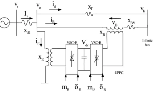
Figure 1 shows a single-machine infinite-bus (SMIB) system equipped with a UPFC. The UPFC consists of an excitation transformer (ET), a boosting transformer (BT), two three-phase GTO based voltage source converters (VSCs), and a DC-link capacitor. The four input control signals to the UPFC are mE, mB, E,
and B, where, mE is the excitation amplitude
modulation ratio, mB is the boosting amplitude
modulation ratio, E is the excitation phase angle and B
is the boosting phase angle.
In dynamic of power systems, it is usually important to aim for decentralization of control action to individual areas. The advantages of this operation philosophy are reduction in the controller complexity and suitability for practical implementation. It is shown that each decentralized controller can be designed independently such that performance of the overall closed loop systems is guaranteed. In this study, in order to reduce the controller complexity, a decentralized control method based on robust µ-synthesis is used for UPFC controller.
o
v t v
t I
tE
x
E
x
T
x
BV
x
tl
i
B
i
B
x
dc
V
VSC-E VSC-B
E
i Infinite
bus b
v
B
v
E
m δE mB δB UPFC
Fig. 1: SMIB power system equipped with UPFC The µ-synthesis technique not only minimizes the maximum error energy for all command disturbance input, but also stabilizes the closed loop system for
structured plant uncertainties with limited H norm. This is especially desirable when designing controllers for plants with unmodeled high frequency dynamics, or when the plants undergo faulty operating conditions or plant parameters vary due to aging such as power system. Due to its practical merit, the proposed control strategy has a decentralized scheme. When a decentralized controller is applied, by reducing the system size, the H norm is easier to dampen and the resulting controller order will be lower, which is ideally useful for the real world complex power system.
DYNAMIC MODEL OF STUDY SYSTEM Non-linear dynamic model: By applying Park’s transformation and neglecting the resistance and transients of the ET and BT transformers, the UPFC can be modeled as[21-23]:
E E d cc
E td E E d
E tq E E q E E d c
m c o s v
v 0 x i
2
v x 0 i m s in v
2
δ −
= +
δ
(1)
B B d c
B td B B d
B tq B B q B B d c
m c o s v
v 0 x i
2
v x 0 i m s i n v
2
δ −
= +
δ
(2)
B
E d E
d c E E
E q d c
B d
B B
B q d c
i 3 m
v [ co s sin ]
i 4 C
i 3 m
[ co s sin ]
i 4 C
= δ δ
+ δ δ
(3)
The nonlinear model of the SMIB system as shown in Fig. 1is described by:
m e
( P P D ) / M
ω = − − ∆ ω (4)
0(1 )
δ = ω − ω (5)
q q fd d o
.
E' = −( E +E ) / T ' (6)
fd fd ref t a
.
(
)
e td td tq tq q qe d d td
t td tq td q tq tq q d td
td tld Ed Bd tq tlq Eq Bq
P V I V I ; E E X X I
V V jV ; V X I ; V E X I
I I I I ; I I I I
′ ′
= + = + −
′ ′
= + = = −
= + + = + +
The equation for real power balance between the series and shunt converters is given by:
B B E E
Re(V I∗ V I )∗ 0
− = (8)
Power system linearised model: A linear dynamic model is obtained by linearising the nonlinear model around an operating condition. The linearised model of power system as shown in Fig. 1 is given as follows:
0
•
∆ δ = ω ∆ω (9)
e
( P D ) / M
∆ω = −∆ − ∆ω (10)
/ /
q q fd do
E ( E E ) / T
•
∆ = −∆ + ∆ (11)
A
fd fd
A A
1 K
E E V
T T
•
∆ = − ∆ − ∆ (12)
/
dc 7 8 q 9 dc ce E
c e E cb B c b B
v K K E K v K m
K K m K
•
δ δ
∆ = ∆δ + ∆ − ∆ + ∆
+ ∆δ + ∆ + ∆δ
(13)
Where,
/
e 1 2 q pd dc pe E
p e E pb B p b B
P K K E K v K m
Kδ K m Kδ
∆ = ∆δ + ∆ + ∆ + ∆
+ ∆δ + ∆ + ∆δ
/ /
q 4 3 q qd dc qe E
q e E qb B q b B
E K K E K v K m
Kδ K m Kδ
∆ = ∆δ + ∆ + ∆ + ∆
+ ∆δ + ∆ + ∆δ
/
t 5 6 q vd dc ve E
v e E vb B v b B
V K K E K v K m
K δ K m K δ
∆ = ∆δ + ∆ + ∆ + ∆
+ ∆δ + ∆ + ∆δ
K1, K2,…,K9, Kpu, Kqu and Kvu are linearization
constants. The state-space model of power system is given by:
x=Ax+Bu (14)
Where, the state vector x, control vector u, A and B are:
D MS+ 1 S w0 1 K 4
K K5
6 K 2 K 7 K 8 K a ST ka + 1 / 3 1 do ST K+ pd K vd K vu K qd K qu K cu K pu K 9 1 K S+ ref V ∆ − − − − + + + + + + + − + + − − − U + e P ∆ m P ∆ / q E ∆ dc V ∆
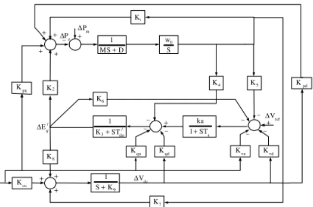
Fig. 2: Linearised dynamic model of the SMIB power system with UPFC
q fd dc
x= ∆δ ∆ω ∆[ E′ ∆E ∆v ]
T
E E B B
u= ∆[ m ∆δ ∆m ∆δ ]
0 pd 1 2 qd 4 3 / / / /
do do do do
A 5 A 6 A vd
A A A A
7 8 9
pe p e pb p b
qe q e qb q b
/ / / /
do do do do
A vc A v e A vb
A A A
0 w 0 0 0
K
K K
0 0
M M M
K
K K 1
0 A
T T T T
K K K K 1 K K
0
T T T T
K 0 K 0 K
0 0 0 0
K K K K
M M M M
K K K K
B
T T T T
K K K K K K
T T T
δ δ δ δ δ − − − − − − = − − − − − − − − − − − − − =
− − − A v b
A
ce c e cb c b
K K T
K K K K
δ
δ δ
−
The block diagram of the linearised dynamic model of the SMIB power system with UPFC is shown in Fig. 2.
) ( 1t y
) (t ym 1
x
m x
) (
1t
u
) (t um )
( 1t r
) (t rm
P
G F
+ -+
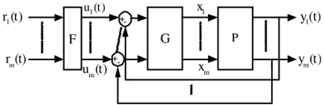
Fig. 3: The MIMO control structure (m×m) system problem of decentralized UPFC controller is translated into an equivalent problem of decentralized control design for a MIMO control system. The proposed method is based on Schauder fixed point theorem [24].
The basic MIMO compensation structure for an m×m MIMO system is shown in Fig. 3. This consists of the uncertain plant P, the diagonal compensation system G, and pre-filter F. These systems are defined as follows:
11 12 1m
21 22 2m
ij
m1 m2 mm
P P P
P P P
P(s) [P ](s)
P P P
= =
(15)
{
}
1
2 i
m
g 0 0
0 g 0
G(s) diag g (s)
0 0 0
0 0 g
= = (16)
11 12 1m
21 22 2 m ij
m1 m 2 mm
f f f
f f f
F(s) [f (s)]
f f f
= = (17)
This section develops a mapping that permits the analysis and synthesis of a MIMO control system by a set of equivalent MISO control system. This mapping results in m2 equivalent systems, each with two inputs and one output. One input is designated as a desired input and the other as a disturbance input. The inverse of the plant matrix is represented by:
11 12 1m
21 22 2m
1
m1 m2 mm
P P P
P P P
P(s)
P P P
∗ ∗ ∗
∗ ∗ ∗
−
∗ ∗ ∗
= (18)
The m2 effective plant transfer function is formed as:
ij
ij ij
1 det p
q
P∗ adj p
⋅
= =
⋅ (19)
There is a requirement that det(P) be minimum phase. The Q matrix is then described by:
11 12 1m
11 12 1m
21 22 2 m
21 22 2m
m1 m 2 mm
m1 m2 mm
1 1 1
P P P
q q q
1 1 1
q q q
P P P
Q
q q q
1 1 1
P P P
∗ ∗ ∗
∗ ∗ ∗
∗ ∗ ∗
= = (20)
Where,
1
ij ij ij
ij ij
1 1
P [P ], P [P ] [ ],Q [q ] [ ]
q P
− ∗
∗
= = = = = .
The matrix P-1 is partitioned to the following form:
1 ij
ij
1
P [P ] [ ] B
q
− ∗
= = = + (21)
Where, is the diagonal part and B is the balance of P-1. The system control ration relating r to y is
1
T [I PG] PGF−
= + . Pre-multiplying of system control ration by [I+PG] yields:
[I+PG]T=PGF (22)
When, P is nonsingular, Pre-multiplying both sides of this equation by P-1 yields:
1
[P− G]T GF
+ = (23)
Using Eq. (21) and with G diagonal, Eq. (23) can be rearranged as follows:
1
T [ G] [GF− BT]
= Λ + − (24)
This is used to define the desired fixed point mapping where each of the m2 matrix elements on the right side of Eq. (24) can be interpreted as a MISO problem. Proof of the fact that design of each MISO system yields a satisfactory MIMO design is based on the Schauder fixed point theorem[24]. This theorem is described by defining a mapping Y(T) by:
1
Y(T) [ G] [GF− BT]
Where, each member of T is from the accepted set ℑ. If this mapping has a fixed point i.e. T∈ℑ such that Y(T) = T, then their T is a solution of Eq. (24).
For each MISO system there is a disturbance input which is a function of all the other loop outputs. The object of the design is to have each loop track its desired input while minimizing the output due to the disturbance inputs.
STRUCTURED SINGULAR VALUE AND µ-BASD UPFC CONTROLLER SYNTHESIS
This section gives a brief overview of -theory[25,26]. Also, the procedure of the -based UPFC controller design is given in subsection B.
Structured singular value and µ- synthesis: The structured singular value ( ) is an appropriate tool for analyzing the robustness and synthesizing of a system subjected to structured linear fraction transformers (LFT). Consider the feedback control system shown in Fig. 4a, with generalized plant P(s), the controller K(s) and the uncertainty block (s). Here, v is the exogenous input vector, e is the error output vector, y is the measured output vector and u is the control input vector to the generalized plant. For the purpose of analysis, controller K is included into plant P to form the interconnected structure in Fig. 4b. Consider an uncertainty with known structure, bounded value and belonging to the set B :
{
}
{
}
m mi j 1 r1 s rs 1 F i j
diag( I ,..., I , ,..., ); C, C
B | ( ) 1
×
∆ = δ δ ∆ ∆ δ ∈ ∆ ∈
∆ = ∆ ∈ ∆ σ ∆ ≤ (26)
For a system described in the complex matrix, n n
M C×
∈ ,
the structural singular value ( ) is defined as:
{
}
1
(M) min ( ) : ,det(I M ) 0
− ∆
µ = σ ∆ ∆ ∈ ∆ − ∆ = (27)
Furthermore, let:
Mµ sup ∆(M( j ))
ω
= µ ω (28)
Thus, µ∆(M)is a measure of the smallest structured
that causes instability of the constant matrix feedback loop shown in Fig. 4b. Given a desired uncertainty level, the purpose of this design is to look for a control law, which can bring down the closed-loop system level and ensure the stability of the system for all possible uncertainty descriptions.
P
K
e y z w
u v
M
u
e z
v w
(b) (a)
u
Fig. 4: (a) Perturbed feedback control system (b)
-analysis
=
22 21
12 11
p p
p p p
∆
K
u y
∆
u y∆
M
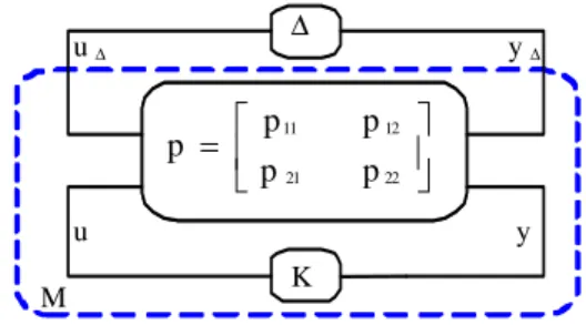
Fig. 5: The standard M- configuration
To design a controller that achieves both robust stability and robust performance, we redraw the system shown in Fig. 4a as a standard M- configuration, which is shown in Fig. 5, where:
{
blokdiag( u); u B ,}
∆ = ∆ ∆ ∈ ∆ (29)
Note that the P includes the nominal plant, the weighting functions and scaling factor so that∆ ∈ ∆u B . The block labeled M can be expressed as the following:
1
L 11 12 22 21
M F (P, K) P P K(I P K) P−
= = + − (30)
Ideally, based on the -theory, the robust stability and performance holds for a given M- configuration if and only if:
K
inf Mµ≤1 (31)
In other words, the performance and stability of the closed-loop system M is a test, across frequency for the given uncertainty structure . Using the performance robustness condition and the well-known upper bound for , the robust synthesis problem to be solved is reduced to the following form:
1 K D
min inf sup (DM( j )D )−
ω
σ ω (32)
1 L
K D
min inf DF (P, K)D−
∞ (33)
By iteratively, solving for D and K (D-K iteration algorithm). Here D is any positive definite symmetric matrix with appropriate dimension and (.)denotes the maximum singular value of a matrix.
µ-based UPFC controller synthesis: The main goals of the UPFC controller design are: Power system oscillation damping, DC-voltage regulator and power flow controller. A damping controller is provided to improve the damping of power system oscillations. This controller may be considered as a lead-lag compensator[22,27] or a fuzzy controller block[28]. However, an electrical torque in phase with the speed deviation is to be produced in order to improve damping of the system oscillation. The block diagram of the damping controller is shown in Fig. 6. The UPFC is installed in one of the two line of the SMIB system. Fig. 7 shows the transfer function of system. The power flow controller regulates the power flow on this line. The real power output of the shunt converter must be equal to the real power input of the series converter or vice versa. In order to maintain the power balance between the two converters, a DC-voltage regulator is incorporated. DC-voltage is regulated by modulating the phase angle of the shunt converter voltage.
-based power flow and DC-voltage controller synthesis: According to the discussion in Sec. 4, we now proceed to design a decentralized power flow and DC-voltage robust controller using the -synthesis technique. MIMO system shown in Fig. 7 decentralized into MISO system as shown in Fig. 8. For each MISO system there is a disturbance input which is a function of all the other loop outputs. In fact, using the mentioned procedure in Sec. 4 the UPFC power flow and DC-voltage regulators controllers are designed independently based on µ technique with this decentralized method.
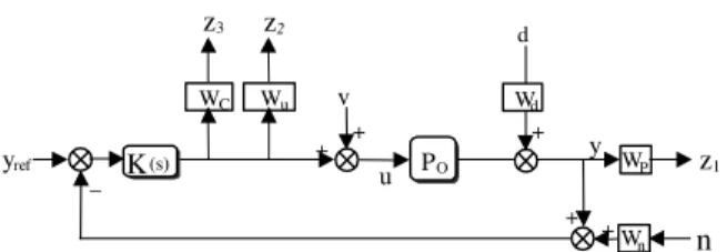
To achieve our objectives and according to -synthesis requirements, we propose the control strategy shown in Fig. 9 for a power flow and DC-voltage. This figure shows the main synthesis strategy for obtaining the desired decentralized controller.
Usually, the uncertainties in power system can be modeled as multiplicative and/or additive uncertainties[29]. In Fig. 9 the ∆u block models the unstructured uncertainties as a multiplicative type and Wu is the associated weighting function. According to
e
P m P
Set point
DC
K
w
w sT sT
+
1 2
1
1 1
sT sT
+ +
Ms 1
−
+ dt
dδ
Block 1
Fig. 6: Transfer function block diagram of the UPFC based damping controller
2 2×
P
DC
V
2
e
P
B
m
E
δ
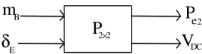
Fig. 7: 2×2 system considered to MIMO plant
B
m mB
E
δ
E
δ
2 e P 2
e P 2 2× P
∗
1 p
∗
2
p Vdc
dc V
d
d
Fig. 8: MIMO system translated into MISO system
+ +
+
+
+ +
+ +
K u
w ∆u
d w
n w d
r n
z
v u
Nominal Model of
system −
− c
w
p w
Fig. 9: The proposed synthesis strategy for UPFC controller
the requirements of performance and practical constraints on control actions, the weighting functions Wc and Wp are added to the control area model. This is
necessary in order to guarantee the feasibility of resulting controller implementation. The, Wc on the
control input sets a limit on the allowed control signal to penalize fast change and large overshoot in the control action. The weight, Wp, at the output sets the
performance goal i.e.: tracking regulation error on the output UPFC control signal. The weight, Wd at the
input disturbances set the normalized. The weight, Wn
z 1
W C
WP
+
K(s) +
_
yref PO
v
u z 3
W u
z 2 d
+
y
Wn n
+ + Wd
Fig. 10: Synthesis framework for UPFC controller
u C P
blockdiag( , P , P )
∆ = ∆ ∆ ∆ (34)
d p 0 p 0 p n 0
1 1 1
u d 0 0 u 0 0 u n 0 0
1 1 1
c d 0 0 u 0 0 c d 0 0
W W S W S W W T
M W W T G W T G W W T G
W W T G W T G W W T G
− − −
− − −
− −
= − −
− −
(35)
where, To and So are complementary sensitivity and
sensitivity functions of the nominal model of system and described by:
1
0 0 0
1
0 0 0
T KG (1 KG )
S I T (1 KG )
−
−
= +
= − = + (36)
Now, the synthesis problem is designing the robust control K(s) such that the Eq. (31) is fulfilled. Based on discussion mentioned in pervious subsection this problem is solved by D-K iteration algorithm using the MATLAB -synthesis toolbox[30]. It should be noted that the order resulting controller by this procedure is usually high. In order to decrease the complexity of computation in the case of high order power systems, appropriated model reduction techniques might be applied to the obtained controller model. In summary the synthesis procedures of the proposed strategy are:
• Formulation of the UPFC control problem as a decentralized control scheme due to Sec. 4 and identify the state space model.
• Identify the uncertainty blocks and associated weighting functions according to dynamic model, practical limits and performance requirements.
• Isolate the uncertainties from the nominal area model; generate the u, PC and PP blocks and
obtaining M- configuration to formulate the desired level of robust performance.
• Start D-K iteration algorithm using the -synthesis toolbox to obtain the optimal controller.
• Reduce the order of the resulting controller by using the standard model reduction techniques and apply -analysis to the closed-loop system with reduced controller to check whether or not the upper bound of remains less than one.
Design of damping controller for stability: The damping controllers are designed to produce an electrical torque in phase with the speed deviation according to phase compensation method. The four control parameters of the UPFC (mB, mE, B and E) can
be modulated in order to produce the damping torque. In this study mB is modulated for damping controller
design. The speed deviation is considered as the input to the damping controller. The structure of UPFC-based damping controller is shown in Fig. 6. It consists of gain, signal washout and phase compensator blocks. The parameters of the damping controller are obtained using the phase compensation technique. The detailed step-by-step procedure to compute the parameters of the damping controllers using phase compensation technique is given in[22, 27]. Due to system parameters given in Appendix, the initial d-q axes voltage, current components and torque angle are computed for the nominal operating condition as follows:
d q
E B
d q
E 0.396 pu; E 0.953 pu
V 1.0233 26.9 pu; V 0.1047 55.87 pu
I 0.4317 pu; I 0.6601 pu; 51.61
= =
= ∠ = ∠ −
= = δ =
For this operating condition, Damping controller mB
with damping ratio of 0.5 is designed and obtained as follows (wash-out block is considered):
536.0145s(s 3.656)
Damping controller
(s 0.1)(s 4.5)
+ =
+ +
SELECTION OF WEIGHTING FUNCTIONS AND CONTROLLER DESIGN
For the nominal operating conditions (P = 1pu, Q = 0.2pu, Vt = 1.032pu), we can consider plant shown in Fig.
10. P is transfer function of system. Weighting functions selection
Uncertainty weights selection: For robust control design, an open-loop system is represented by nominal plant model Pnom(s) and the uncertainty set which
covers the differences between Pnom(s) and reality of the
nominal linear plant model. The percentage of model uncertainty is represented by the weight WuPe and WuVdc
which corresponds to the frequency variation of the model uncertainty. These weighting functions are chosen to cover the maximum uncertainty as follows:
upe
3s W
50s 1 =
+ , uVdc
5s W
50s 1 =
+
Performance weights selection: As we discussed earlier in order to guarantee robust performance and satisfy the control objectives of SMIB and UPFC problems, we need to add for each of the control Pe2 and
Vdc, a fictitious uncertainty block along with the
corresponding performance weights WC and WP
associated with the control effort and control error minimization, respectively. The selection of WC and WP
entails a trade-off among different performance requirements, particularly good regulation versus peak control action. The weight on the control input WC must
be chosen close to a differentiator to penalize fast change and large overshoot in the control input. The weight on the output error, WP, must be close to an
integrator at low frequencies in order to get zero steady-state error, good tracking and disturbances rejection. On the other hand, an important issue with regard to selection of these weights is degree for achieving performance objectives. Moreover, in order to keep the controller complexity low, the order of selected weights should be kept low. More details on how these weights are chosen are given in[25, 31]. Based on the above discussion, a suitable set of performance weighting functions for Pe2 and Vdc is chosen as:
P _ Vdc
(s /100 15) W
(s .0001 15) + =
+ × ; C _ Vdc
0.8s W
0.1s 1 =
+
P _ Pe
(s / 30 .4) W
(s .0001 .4) + =
+ × ; C _ Pe
0.3s W
0.1s 1 =
+
d _ Vdc
W =0.2 ; Wn _ Vdc=0.05
d _ Pe
W =0.1 ; Wn _ Pe=0.05
-based control design: According to the synthesis methodology described in pervious section, our next task is to isolate the uncertainties from the nominal area model and redraw the system in the standard M- configuration as shown in Fig. 5. Now, due to synthesis methodology as given in Sec. 5, the robust synthesis problem is obtained in terms of the theory and the
-analysis. Synthesis toolbox of MATLAB is used to obtain optimal controller. The controllers Kpe2 and Kvdc
are found at the end of the first D-K iteration, yielding the values of about 0.935 and 0.995 on the upper bound on , respectively. Thus, the robust performance is guaranteed. The resulting controllers Kpe2 and Kvdc are
of dynamic type and have a high order (12th and 11th). The controllers are reduced to a 3rd and 5th order with no performance degradation using the standard Henkel norm approximation. The transfer functions of the reduced order controllers are given by:
Pe 2
(s 176.9)(s 2.316)(s 0.1244)
K 0.011
s(s 2.579)(s 10000)
+ + +
=
+ +
2
Vdc 2
(s 2.88)(1.406)(s 0.9035s 3.203)
K 30390
s(s 30.31)(s 9.35)(s 0.8s 32.94)
+ + +
=
+ + + +
CONVENTIONAL UPFC CONTROLLER Conventional controller is used for comparison of proposed method. In conventional method, P-I type controller is considered for power-flow controller and DC-voltage regulator. Figure 11 and 12 shows the transfer function of the P-I type power-flow controller and P-I type DC-voltage regulator, respectively. The optimal parameters of the power-flow controller (kpp
and kpi) and DC-voltage regulator (kdp and kdi) are
obtained using genetic algorithm[32] for operating condition 1 as listed in Appendix. Optimal values of the proportional and integral gain setting of the power-flow controller are obtained as kpp = 0.5385 and kpi = 1.8259.
When the parameter of power-flow controller are set at their optimal values. The parameters of DC-voltage
Damping controller
s k k p i
p p+
-+ ++
ref e P2
ω ∆
2 e P
B m
Fig. 11: PI- type power-flow controller with damping controller
+ - dcref
V
dc V
s k k d i
d p+ δe
regulator are now optimized and obtained as kdp = 0.398
and kdi = 0.5778. It should be noted that, the damping
controller which designed earlier, for stability, is considered in this section with the same structure, and conventional controllers are designed by application of cited damping controller.
RESULTS AND DISCUSION
In this section different comparative cases are examined to show the effectiveness of the proposed µ-based controller. This case is evaluated extensively by time domain simulation, through the usage of commercially available software package[30]. Each simulation result presented in this section consists of two different plots (i.e.: conventional UPFC (C-UPFC) and µ-based UPFC), for comparative studies.
The performance of the designed µ-based UPFC and C-UPFC controllers with the same damping controller mB after sudden change in reference power
on transmission line 2 and reference mechanical power, are compared and shown in Fig. 13 to 16. Finally, in Fig. 17 power system responses under a transitory 3-phase fault is shown. The loading condition and system parameters are given in Appendix.
Transient deviation in the power flow on line 2: In this case three different situations including nominal, heavy and very heavy loads are considered. A power system response for 10% changes in Pe2ref, i.e.,
transient deviation in the power flow on line 2 following a 10% step change in reference power on line 2 are depicted in Fig. 13-15 for the three operating points (nominal, heavy and very heavy load conditions), respectively.
It can be observed from these figures, which the proposed method significantly damp power system oscillations compared to conventional UPFC controllers.
Transient deviation in the mechanical power: In this case three different situations including nominal, heavy and very heavy loads are considered. Fig. 16 shows the dynamic responses for m, i.e., transient deviation in
the mechanical torque following a 10% step change in reference mechanical torque, with µ-based UPFC and C-UPFC for the three operating points.
From the Fig. 16, it can be seen that the proposed µ-based UPFC controllers is very effective, achieve good robust performance and compared to C-UPFC have the best ability to reduce power system low frequency oscillations.
(a) (c)
0 5 10 15
0 0.02 0.04 0.06 0.08 0.1 0.12
Time(s)
∆
P
e
Time(s)
0 5 10 15
-2.5 -2 -1.5 -1 -0.5 0 0.5
1 x 10⁻³
∆
VD
C
0 5 10 15
-2.5 -2 -1.5 -1 -0.5 0 0.5 x 10⁻⁴
Time(s)
∆
W
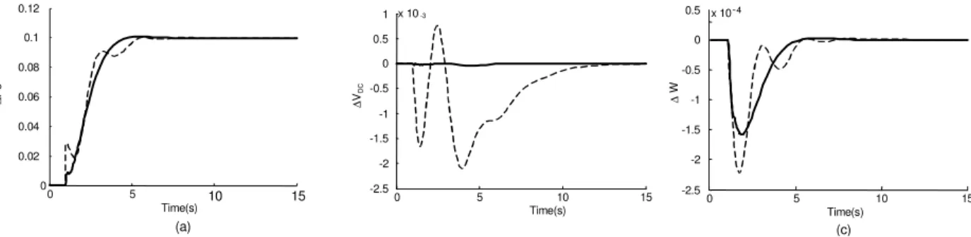
Fig. 13: Power system response at operating point 1 (Nominal loading) under Pe2ref=0.1 pu; Solid (µ-based) and
Dashed (Classical) (a) Power flow deviation on line (b) DC- voltage deviation (c) Speed deviation
(a) ( c)
0 5 10 15
0 0.02 0.04 0.06 0.08 0.1 0.12
Time(s)
∆
P
e
0 5 10 15
-2 0 2 4 6 8 10 x 10-3
Time(s)
∆
VD
C
(b)
0 5 10 15
-2 -1 0 1 2 x 10⁻⁴
Time(s)
∆W
Fig. 14: Power system response at operating point 5 (Heavy loading) under Pe2ref=0.1 pu; Solid (µ-based) and
(a) (b) (c)
0 5 10 15
0 0.05 0.1 0.15 0.2
Time(s)
∆
P
e
0 5 10 15
-0.01 -0.005 0 0.005 0.01
Time(s)
∆
VD
C
0 5 10 15
-6 -4 -2 0 2 4 6x 10⁻⁴
Time(s)
∆
W
Fig. 15: Power system response at operating point 5 (Very heavy loading) under Pe2ref=0.1 pu; Solid (µ-based) and
Dashed (Classical) (a) Power flow deviation on line (b) DC- voltage deviation (c) Speed deviation
x10-3
0 2 4 6 8 10
-5 0 5
Time(s)
∆
W
(a)
0 2 4 6 8 10
-2 -1 0 1 2 3x 10⁻³
Time(s)
∆
W
(b)
0 5 10 15
-0.03 -0.02 -0.01 0 0.01 0.02
Time(s)
∆
W
(c)
Fig. 16: Speed deviation under Tm = 0.1 pu; Solid (µ-based) and Dashed (Classical) (a) At operating point 1 (b) At
operating point 2 (c) At operating point 3
(a)
0 2 4 6 8 10
0.9999 1 1.0001 1.0002
Time(s)
W
0 2 4 6 8 10
0.9998 0.9999 1 1.0001 1.0002 1.0003 1.0004 1.0005
W
Time(s) 0 1 2 3 4 5
0.998 0.999 1 1.001 1.002 1.003
W
(b) (c)
Time(s)
Fig. 17: Speed deviation for a transitory 3-phase fault at the generator terminals, Solid (µ-based) and Dashed (Classical) (a) For
10ms duration at operating point 1 (b) For 15ms duration at operating point 1 (c) For 12ms duration at operating point 2
Performance of damping controllers under large perturbations: In order to investigate the performance of the proposed controller and the system behavior under large disturbances and various operating conditions, a transitory 3-phase fault of 10-15 ms duration at the generator terminal is considered. Dynamic performance is obtained using the non-linear model under the system of the nominal and heavy loading condition with µ-based and optimal settings of the UPFC controllers (Power-flow controller, DC-voltage regulator and damping controller). Figure 17 shows the power system responses under the above
operating condition. These figures show the superiority of proposed µ-based controller over its conventional counterpart. Also, effectiveness of the proposed control strategy in damping the local low frequency oscillations with UPFC is confirmed.
CONCLUSION
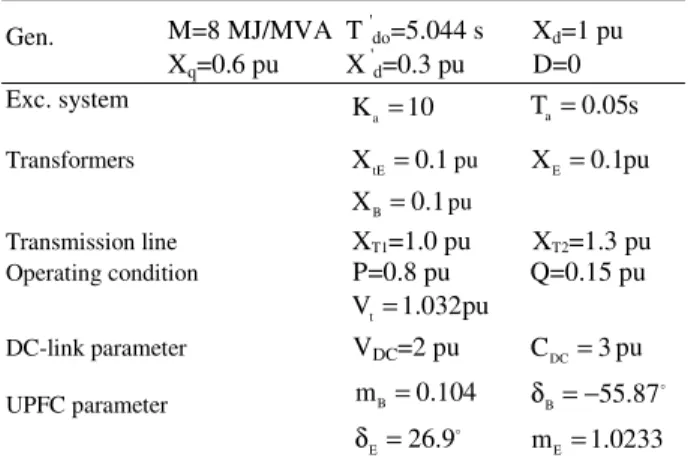
Table 1: System parameters
Gen. M=8 MJ/MVA T 'do=5.044 s Xd=1 pu
Xq=0.6 pu X 'd=0.3 pu D=0
Exc. system
a
K =10 Ta=0.05s
Transformers XtE=0.1pu XE=0.1pu
B
X =0.1pu
Transmission line XT1=1.0 pu XT2=1.3 pu
Operating condition P=0.8 pu Q=0.15 pu
t
V=1.032pu
DC-link parameter VDC=2 pu CDC=3pu
UPFC parameter mB=0.104 δ = −B 55.87
E 26.9
δ = mE=1.0233
Table 2: Operating conditions
Nominal Load P=0.80 Q=0.15 Vt=1.032
Heavy Load P=1.125 Q=0.285 Vt=1.032
Very Heavy Load P=1.15 Q=0.30 Vt=1.032
control strategy is flexibility of the synthesis procedure for modeling uncertainty, direct formulation of performance objectives and practical constraints. Due to its practical merit, the proposed control strategy has a decentralized scheme. The advantages of this operation philosophy are reduction in the controller complexity by reducing the system size and suitability for practical implementation which is ideally useful for the real world complex power system. The time domain linear and nonlinear time simulation results show that it has good performance on damping low frequency oscillations and improves the transient stability under different operating conditions and disturbances. This controller in order to generate good quality and reliable electric energy in the power systems.
APPENDIX
The nominal parameters and operating condition of the system are listed in Tables 1 and 2. The uncertainty area for active and reactive power is as:0.7≤P≤1.15
and 0.1 Q≤ ≤0.3.
REFERENCES
1. Pai, M.A., 1989. Energy Function Analysis for Power System Stability, Dordrecht: Kluwer Academic Publishers.
2. Tambey, N. and M. Kothari, 2003. UPFC Based Damping Controllers for Damping LFO in a Power System, http://www.ieindia.org/publish/el/0603. 3. So, P.L. and T. Yu, 2000. Coordination of TCSC
and SVC for Inter-Area Stability Enhancement, IEEE Trans. PWRD, Vol. 9, No. 1.
4. Swift, F.J., H.F. Wang and M. Li, 1996. Analysis of Controllable Series Compensator to Suppress Power System Oscillations, In: Proceeding of International Conference on AC and DC power transmission.
5. Al-Awami, A.T. et al., 2007, A PSO-Based Approach of Power System Stability Enhancement with UPFC, E. Power and Energy Sys. (29): 251-9. 6. Padiyar, K.R. and H.V. Saikumar, 2005.
Coordinated Design and Performance Evaluation of UPFC Supplementary Modulation Controllers, Elect. Power and Energy Sys. (27): 101-111. 7. Gyugyi, L., 1992. UPFC Concept for FACTS, IEE
Proc. -C, 139 (4): 323-31.
8. IEEE Power Eng. Society and CIGRE, 1995. FACTS Overview, IEEE pub. No. 95 TP 108. 9. Song, Y.H. and A.T. Johns, 1999. Flexible AC
Transmission Systems , UK: IEE Press.
10. Huang, Z. et al., 2000. Application of UPFC in Interconnected Power Systems-Modeling, Interface, Control Strategy and Case Study, IEEE Trans. PWRS, 15 (2): 817-824.
11. Stefanov, P.C., Stankovic A.M., 2002. Modeling of UPFC Operation Under Unbalanced Conditions with Dynamic Phasors, IEEE Trans. PWRS, 17 (2): 395-403.
12. Tambey, N. and M.L. Kothari, 2003. Damping of PSO with UPFC, IEE Proc.-C, 150 (2): 129-140. 13. Farsangi, M.M. et al., 2004. Choice of FACTS
Device Control Input for Damp. I.A. Oscillation, IEEE TPWRS, 19 (2): 1135-43.
14. Mishra, S., P.K. Dash and G. Panda, 2000, TS-Fuzzy Controller for UPFC in a Multi-Machine System, IEE Proc.-C, 147 (1): 15-22.
15. Schoder, K. et al., 2001. Power System Damping Using Fuzzy Controlled UPFC, In: Proc. of the IEEE PES Winter Meeting 2001, 2: 617-622. 16. Dash, P.K. et al., 2000. A Radial Basis Function
Neural Network Controller for UPFC, IEEE Trans. PWRS, 15 (4): 1293-1299.
17. Vilathgamuwa, M. et al., 2000. A Robust Control Method to Improve the Performance of a UPFC, Elec. Power Sys Res. (55): 103-111.
19. Seo, J.-C. et al., 2001. Design of a Robust UPFC Controller for Enhancing the Small Signal Stability in the Multi-Machine Power Systems, In: Proc. of the IEEE PES Winter Meeting, 3: 1197-202. 20. Taher, S.A. et al., 2008. Design of Robust UPFC
Controller using H Control Theory in Electric Power System, American Journal of Applied Sciences, 5 (8): 980-989.
21. Nabavi, A. and M.R. Iravani, 1996. Steady-State and Dynamic Models of UPFC for Power System Studies, IEEE TPWRS, 11 (4): 1937-43.
22. Wang, H.F., 1999. Damping Function of UPFC, IEE Proc.-C, 146 (1): 81-87.
23. Wang, H.F., 1999. Application of Modeling UPFC into Multi-Machine Power Systems, IEE Proc.-C, 146, (3): 306-312.
24. Horowitz, I.M., 1979. Quantitative Synthesis of the Uncertain MIMO Feedback Systems, Int. J. Control (30): 81-106.
25. Skogested, S. and I. Postlethwaite, 1996. Multivariable Feedback Control, John Wiley and Sons.
26. Shayeghi, H. and H.A. Shayanfar, 2006. Application of ANN Technique Based on µ-Synthesis to LFC of Interconnected Power System, Elect. Power and Energy Sys. (28): 503-511. 27. Yu, Y.N., 1983. Electric Power System Dynamics,
Academic Press, Inc., London.
28. Eldamaty, A.A. et al., 2005. Damping PSO Using a Fuzzy Logic Based UPFC, in: Proc. the IEEE CCECE/CCGEI, 1: 1950-1953.
29. Djukanovic, M.B. et al., 2000. Sensitivity Based Structured Singular Value Approach to Stability Robustness of Power Systems, IEEE Trans. PWRS, 15 (2): 825-830.
30. Balas, G.J. et al., 2006. The -Analysis and Synthesis Toolbox for Use with MATLAB, The Mathworks Inc., South Natick.
31. Shayeghi, H., and M. Karrari, 2000. Theory of Synthesis for Power Systems LFC, J. Elec. Eng. 51: 258-263.