American Journal of Engineering Research (AJER)
e-ISSN: 2320-0847 p-ISSN : 2320-0936
Volume-6, Issue-1, pp-37-43
www.ajer.org
Research Paper Open Access
Voltage Stability Enhancement and Efficiency Improvement of
Nigerian Transmission System Using Unified Power Flow
Controller
Adeniji O.A.
1& Mbamaluikem P.O.
21,2Department of Electrical Engineering, The Federal Polytechnic, Ilaro, Ogun State
ABSTRACT:
Consistent increase in the demand for electrical energy often leads to heavy loading of transmission lines. One of the consequences of this is that such transmission systems are subjected to imbalance in the reactive power and hence voltage instability and reduction in real power of the system. Conventional methods of enhancing voltage stability and improving efficiency have proven to be slow and difficult to control. A new approach, however, is the use of Flexible AC Transmission System (FACTS) controllers. This paper applied Unified Power Flow Controller (UPFC), a member of this class of devices to Nigeria’s 330kV transmission system using MATLAB. Obtained results showed an improvement in the voltage magnitude of bus 9 and bus 13 from 0.9896 and 0.9765 to 1.02 and 1.0199 respectively. Also, the active power loss was reduced by 2.53% from 85.177MW to 83.025MW when UPFC was applied. Incorporation of UPFC improved the system’s voltage stability and reduced active power losses. The UPFC could therefore be deployed to minimize prolonged and frequent voltage instability in transmission networks and enhance system efficiency.Keywords:
Transmission system, voltage instability, FACTS devices, UPFC, MATLABI.
INTRODUCTION
Transmission systems are part of the overall electrical power supply systems. Transmission system consists of conductors carried on steel towers linking generation stations to users through the distribution system. They deliver bulk power from power stations to the load centers and large industrial consumers beyond the economical service range of the regular primary distribution lines [1]. Like many transmission systems in the world, Nigeria’s transmission system is characterized by high technical and non-technical losses, overloading, voltage instability, radial lines having no redundancy, results of de-regularization of the electricity market and obsolete substation equipment [2],[3],[4].
Increase in population leads to increase in economic activities and hence increase in electrical energy demand, thereby causing burdens on existing transmission lines also to increase. This has caused the loading of the transmission lines beyond their design limits with consequent reduction in power quality [5][6].
A major consequence of overstretching transmission lines is voltage instability. Voltage instability is defined as the inability of a power system to maintain steady voltages at all buses in the system under normal operating conditions and after being subjected to a disturbance. Instability may result in the form of a progressive fall or rise of voltage of some buses. The possible outcome of voltage instability is loss of load in the area where voltages reach unacceptably low values or a loss of integrity of the power system. Voltage instability could be due to large disturbance or small disturbance [7][8][9].
The proximity of a given system to voltage instability is typically assessed by indices that measure one or a combination of:
• Sensitivity of load bus voltage to variations in active power of the load.
• Sensitivity of load bus voltage to variations in injected reactive power at the load bus. • Sensitivity of the receiving end voltage to variations in sending end voltage.
• Sensitivity of the total reactive power generated by generators, synchronous condensers, and SVS to variations in load bus reactive power [10]
Conventional Methods Of Improving Voltage Stability
There are various conventional methods of improving the voltage stability of power systems. Some of these are:
(a) Reactive Power Compensation
active power to loads, thus releasing system capacity, reducing system losses, and improving system power factor and bus voltage profile [11]. Through controlling the production, absorption, and flow of reactive power at all levels in the system, voltage/Var control can maintain the voltage profile within acceptable limit and reduce the transmission losses [9].
Compensation could be shunt whereby the compensating device is connected in parallel with the circuit to be compensated. It can be capacitive (leading) or inductive (lagging) reactive power, although in most cases, compensation is capacitive. Shunt compensation is successful in reducing voltage drop and power loss problems in the network under steady load conditions as it reduces the current flow in areas of installation [12][13]. It could also be series whereby the compensating device is connected in series with the circuit to be compensated. Whereas shunt compensation reduces the current flow in areas of installation, series compensation acts directly on the series reactance of the line. It reduces the transfer reactance between supply point and the load and thereby reduces the voltage drop [14].
(b) Synchronous Condensers
Synchronous condenser is simply a synchronous machine without any load attached to it. Like generators, they can be over-exited or under-exited by varying their field current in order to generate or absorb reactive power. Synchronous condensers can continuously regulate reactive power to ensure steady transmission voltage, under varying load conditions. They are especially suited for emergency voltage control under loss of load, generation or transmission, because of their fast, short-time response. Synchronous condensers provide necessary reactive power even exceeding their rating for short duration, to arrest voltage collapse and to improve system stability [15][16].
(c) Excitation Control
When the load on the supply system changes, the terminal voltage of the alternator also varies due to the changes in voltage drop in the synchronous reactance of the armature. Since the alternators have to be run at a constant speed, the induced emfs, therefore, cannot be controlled by adjustment of speed. The voltage of the alternator can be kept constant by changing the field current of the alternator in accordance with the load. This is known as EXCITATION CONTROL METHOD. The excitation control method is satisfactory only for relatively short transmission lines [1][16].
(d) Tap-Changing Transformers
Tap-changing transformer method is a method of voltage control for long transmission lines where main transformer is necessary. The principle of regulating the secondary voltage is based on changing the number of turns on the primary or secondary i.e. on changing the ratio of transformation. Decrease in primary turns causes increase in emf per turn, and so in secondary output voltage. Secondary output voltage can also be increased by increasing secondary turns and keeping primary turns fixed. In other words, decrease in primary turns has the same effect as that of increase in secondary turns [17].
(e) Booster Transformer
Sometimes, it is desired to control the voltage of a transmission line at a point far away from the main transformer. This can be conveniently achieved by the use of a booster transformer. The secondary of the booster transformer is connected in series with the line whose voltage is to be controlled. The primary of this transformer is supplied from a regulating transformer fitted with on-load tap-changing gear. The booster transformer is connected in such a way that its secondary injects a voltage in phase with the line [16]
(f) Phase-Shifting Transformers
This is based on the concept that modification of voltage magnitudes and / or their phase can be achieved by adding a control voltage. A special form of a 3-phase–regulating transformer is realized by combining a transformer that is connected in series with a line to a voltage transformer equipped with a tap changer. The windings of the voltage transformer are so connected that on its secondary side, phase-quadrature voltages are generated and fed into the secondary windings of the series transformer. Thus the addition of small, phase-quadrature voltage components to the phase voltages of the line creates phase-shifted output voltages without any appreciable change in magnitude. A phase-shifting transformer is therefore able to introduce a phase shift in a line [18].
II.
UNIFIED POWER FLOW CONTROLLER (UPFC)
The Unified Power Flow Controller (or UPFC) is an electrical device for providing fast-acting reactive power compensation on high-voltage electricity transmission networks. The UPFC uses solid state devices, which provide functional flexibility, generally not attainable by conventional Thyristor controlled systems. The UPFC is a combination of a static synchronous compensator (STATCOM – shunt converter) and a static synchronous series compensator (SSSC – series converter) coupled via a common DC voltage link as seen below [22][23][24].
Figure 1: Schematic diagram of the Unified power flow controller (UPFC) system showing two back-to-back
voltage source converters (VSCs)[25].
III.
UPFC POWER FLOW MODEL
The equivalent circuit diagram of the UPFC is shown in Figure 2,
Figure 2: Equivalent circuit diagram of UPFC [25]
The UPFC voltage sources are [21]: ��ℎ = ��ℎ(cos��ℎ+ sin��ℎ) (1)
��� = ���(cos���+ sin���) (2)
whereVsh and δsh are the controllable magnitude (Vsh min ≤ Vsh≤ Vsh max) and phase angle (0 ≤ δsh ≤ 2π)
of the voltage source representing the shunt converter. The magnitude Vse and phase angle δse of the voltage
source representing the series converter are controlled between limits (Vse min ≤ Vse≤ Vse max) and (0 ≤ δse≤ 2π)
respectively
The power flow equations for the UPFC are obtained as follows [21][26]: At the sending-end node i,
� = + = �2− � ���∗ − � �∗ ���∗ + �2− � ��ℎ∗ ��ℎ (3) At the sending-end node k,
The series converter power is:
��� = ������∗ = ��+ �� = ���(�∗− ���∗− �∗)���∗ (5)
Shunt converter power:
��ℎ = ��ℎ��ℎ∗ = �ℎ+ �ℎ = ��ℎ(�∗− ��ℎ)��ℎ∗ (6)
For the case when the UPFC controls the following parameters [16]: (1) Voltage magnitude at the shunt converter terminal (bus i), (2) Active power flow from bus k to bus i, and
(3) Reactive power injected at bus k, and taking bus k to be a PQ bus, The linearised system of equations is as follows [16]:
∆ ∆ ∆ ∆ ∆ ∆ ∆ �� = � �� � �� � �� � �� � �� � �� � �� �� � �� � ���ℎ��ℎ
� �� � � ���� � ������� � ���ℎ � �� 0 � �� � � ���� �
������� 0
� ��
� ���ℎ��ℎ
� �� � � ���� � ������� � ���ℎ � �� 0 � �� � � ���� �
������� 0
� �� 0 � �� � � ���� �
������� 0
� �� 0 � �� � � ���� �
���� ��� 0
� �� ��
� �� ���ℎ��ℎ
� �� �� � � �� ���� � �� ���� ��� � �� ���ℎ ∆� ∆� ∆��ℎ ��ℎ ∆� � ∆��� ∆��� ��� ∆��ℎ
IV.
THE NIGERIAN TRANSMISSION SYSTEM
–
TEST CASE
The test case for this work is the 28-bus Nigerian transmission system made up of nine (9) generating stations/PV buses (which are either thermal or hydro and exluding the Nigerian Integrated Power Projects (NIPPs) and the Independent Power Projects (IPPs)) and fifty-two (52) transmission lines.
Some of the predominant features of this system are:
1. There is an installed capacity of 8,644MW of generated power of which 6,905MW is government owned [27].
2. The system is characterised by high power losses and frequent voltage instability [28]. The transmission grid system is also characterised by radial, fragile and long transmission lines, some of which risk total or partial system collapse in the event of major fault occurrence and make voltage control difficult [29][30]. 3. The existing system comprises over 11,000km of transmission lines (about 5,523km for 330kV lines and
about 6,889km for 132 kV lines) [31]. There are 32 No of 330/132 kV substations with total installed transformation capacity of 7,688MVA (equivalent to 6,534.8MW) [31][32].
Bus and line data of the Nigerian 28-bus system are presented in the tables that follow.
Table 1: Bus data of the Nigerian 330kV 28-Bus transmission System [31].
LOAD GENERATION
BUS NO VOLT MAG (|V|)pu PHASE ANGLE (DEG) PD QD PG QG QMIN QMAX
1 1.05 0 68.9 51.7 0.0 0 -1006 1006
2 1.05 0 0.0 0.0 670.0 0 -1030 1000
3 1.00 0 274.4 205.8 0.0 0 0 0
4 1.00 0 344.7 258.5 0.0 0 0 0
5 1.00 0 633.2 474.9 0.0 0 0 0
6 1.00 0 13.8 10.3 0.0 0 0 0
7 1.00 0 96.5 72.4 0.0 0 0 0
8 1.00 0 383.3 287.5 0.0 0 0 0
9 1.00 0 275.8 206.8 0.0 0 0 0
10 1.00 0 201.2 150.9 0.0 0 0 0
11 1.05 0 52.5 39.4 431.0 0 -1000 1000
12 1.00 0 427.0 320.2 0.0 0 0 0
13 1.00 0 177.9 133.4 0.0 0 0 0
14 1.00 0 184.6 138.4 0.0 0 0 0
15 1.00 0 114.5 85.9 0.0 0 0 0
17 1.00 0 11.0 8.2 0.0 0 0 0
18 1.05 0 0.0 0.0 495.0 0 -1050 1050
19 1.00 0 70.3 52.7 0.0 0 0 0
20 1.00 0 193.0 144.7 0.0 0 0 0
21 1.05 0 7.0 5.2 624.7 0 -1010 1010
22 1.00 0 199.8 149.9 0.0 0 0 0
23 1.05 0 320.1 256.1 388.9 0 -1000 1000
24 1.05 0 20.6 15.4 190.3 0 -1000 1000
25 1.00 0 110.0 89.0 0.0 0 0 0
26 1.00 0 290.1 145.0 0.0 0 0 0
27 1.05 0 0.0 0.0 750.0 0 -1000 1000
28 1.05 0 0.0 0.0 750.0 0 -1000 1000
Table 2: Line Data of Nigerian 330kV 28-Bus transmission System [31].
FROM BUS TO BUS RESISTANCE [R] pu REACTANCE [X] pu 1/2 B (SUSCEPTANCE)
3 1 0.0006 0.0044 0.2950
3 1 0.0006 0.0044 0.2950
4 5 0.0007 0.0050 0.0333
4 5 0.0007 0.0050 0.0333
1 5 0.0023 0.0176 0.1176
1 5 0.0023 0.0176 0.1176
5 8 0.0110 0.0828 0.5500
5 8 0.0110 0.0828 0.5500
5 9 0.0054 0.0405 0.2669
5 10 0.0099 0.0745 0.4949
6 8 0.0077 0.0576 0.3830
6 8 0.0077 0.0576 0.3830
2 8 0.0043 0.0317 0.2101
2 7 0.0012 0.0089 0.0589
7 24 0.0025 0.0186 0.1237
8 14 0.0054 0.0405 0.2691
8 10 0.0098 0.0742 0.4930
8 24 0.0020 0.0148 0.0982
8 24 0.0020 0.0148 0.0982
9 10 0.0045 0.0340 0.2257
15 21 0.0122 0.0916 0.6089
15 21 0.0122 0.0916 0.6089
10 17 0.0061 0.0461 0.3064
10 17 0.0061 0.0461 0.3064
10 17 0.0061 0.0461 0.3064
11 12 0.0010 0.0074 0.0491
11 12 0.0010 0.0074 0.0491
12 14 0.0060 0.0455 0.3025
13 14 0.0036 0.0272 0.1807
13 14 0.0036 0.0272 0.1807
16 19 0.0118 0.0887 0.5892
17 18 0.0002 0.0020 0.0098
17 18 0.0002 0.0020 0.0098
17 23 0.0096 0.0721 0.4793
17 23 0.0096 0.0271 0.4793
17 21 0.0032 0.0239 0.1589
17 21 0.0032 0.0239 0.1589
19 20 0.0081 0.0609 0.4046
20 22 0.0090 0.0680 0.4516
20 22 0.0090 0.0680 0.4516
20 23 0.0038 0.0284 0.1886
20 23 0.0038 0.0284 0.1886
23 26 0.0038 0.0284 0.1886
23 26 0.0038 0.0284 0.1886
12 25 0.0071 0.0532 0.3800
12 25 0.0071 0.0532 0.3800
19 25 0.0059 0.0443 0.3060
19 25 0.0059 0.0443 0.3060
25 27 0.0079 0.0591 0.3900
25 27 0.0079 0.0591 0.3900
5 28 0.0016 0.0118 0.0932
5 28 0.0016 0.0118 0.0932
V.
RESULTS
AND
DISCUSSION
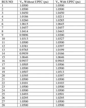
Table 3: Summarized results and Comparison of Voltage Magnitudes with and without the UPFC for 28-Bus Nigerian System
BUS NO Vm Without UPFC (pu) Vm With UPFC (pu)
1 1.0500 1.0500
2 1.0500 1.0500
3 1.0450 1.0450
4 1.0186 1.0211
5 1.0260 1.0285
6 1.0615 1.0645
7 1.0457 1.0457
8 1.0414 1.0443
9 0.9896 1.0200
10 1.0313 1.0327
11 1.0500 1.0500
12 1.0381 1.0397
13 0.9765 1.0199
14 0.9939 1.0166
15 1.0646 1.0646
16 0.9937 0.9945
17 1.0505 1.0506
18 1.0500 1.0500
19 1.0507 1.0513
20 1.0395 1.0397
21 1.0500 1.0500
22 1.0101 1.0103
23 1.0500 1.0500
24 1.0500 1.0500
25 1.0493 1.0501
26 1.0295 1.0295
27 1.0500 1.0500
28 1.0500 1.0500
Without the UPFC, voltages at buses 9 (0.9896 p.u) and 13 (0.9765 p.u) were seen to be the least. For the developed MATLAB program, convergence occurred after six (6) iterations and the maximum power mismatch = 5.62078e-013. The generated reactive power is 844.8101Mvar. The base MVA is 100MVA while the base voltage is 330kV. With the inclusion of UPFC, convergence occurred after seventeen (17) iterations and the maximum power mismatch was found to be 1.6942e-013 while the reactive power has changed from 844.8101Mvar to 639.117Mvar.
In terms of power losses, these reduced paving the way for better efficiency. Without the UPFC installed, the total losses in the lines are 85.177MW. The highest losses were experienced on the lines between buses 25 and 27 with the value put at 10.28MW. When UPFC was installed, the losses reduced by 2.53% to 83.025 MW.
VI.
CONCLUSION
This work has been able to establish the importance derivable from the application of FACTS devices on transmission systems using the Nigerian 330kV, 28-Bus transmission system as a case study. It could be seen how the class of device can improve voltage profiles and reduce transmission losses. They could therefore be deployed to minimize prolonged and frequent voltage instability in transmission networks and enhance system efficiency.
REFERENCES
[1]. J.B. Gupta, A Course in Power Systems (S.K.Kataria and Sons, New Delhi, 10th Edition, 2008)
[2]. S. Richa, V. Kumar and S.H. Dhiraj, Voltage Instability and its prevention using FACTS controllers, International Journal of
Engineering Research and Development, 3(11), 2012, p6-8
[3]. P.Elechi and E. Omorogiuwa, Economic Effect of Technical and Non-Technical Losses in Nigeria Power Transmission System,
Journal of Electrical and Electronics Engineering, 10(2), 2015, p89- 100
[4]. H.S. Labo, “Current Status and Future Outlook of Current Status and Future Outlook of the Transmission Network: A paper
presented at the Investors’ Forum For The Privatization Of PHCN Successor Companies”, 2011
[5]. E. U. Oleka, S. N. Ndubisi, and G. K. Ijemaru, Electric Power Transmission Enhancement: A Case of Nigerian Electric Power Grid, American Journal of Electrical and Electronic Engineering, 4(1), 2016, p 33-39. doi: 10.12691/ajeee-4-1-5.
[6]. US-Canada-Power-System_Outage-Task-Force, "Final Report on the August 14, 2003 Blackout in the United States and Canada: Causes and Recommendations," 2004, [Online] Available: www.energy.gov/sites/prod/files/oeprod/DocumentsandMedia/Blackout Final-Web.pdf.
[7]. C.W. Taylor, Power System Voltage Stability (McGraw-Hill, New York, 1994)
[10]. Y. Mansour, (Editor), Voltage Stability of Power Systems: Concepts, Analytical Tools, and Industry Experience, IEEE Special
Publication # 90TH0358-2-PWR, 1990.
[11]. F.M. Nurul, “Power Quality and Reactive Power Compensation Study”, Unpublished M.Sc Thesis, Faculty of Electrical and Electronics Engineering, University Malaysia Pahang, 2010
[12]. H. Saadat, Power System Analysis (2nded,) (McGraw-Hill Higher Education, 2009)
[13]. T. J. E. Miller, Reactive Power Control in Electric Power Systems, (New York Wiley Interscience Publication, 1982). ISBN 0-471-86933-3
[14]. C.L. Wadhwa, Power Systems (4th Edition), (New Age International (P) Limited, Publishers)
[15]. H. K. Tyll and F. Schettler, Historical overview on dynamic reactive power Compensation solutions from the begin of AC power transmission towards present applications, IEEE Explore Digital Library, 2009, 978-1-4244-3811-2/09
[16]. V.K.Mehta and R. Mehta. Principles of power system, Multicolor illustrative Edition, (S Chand Publishers, 2009)
[17]. K. Vasudevan, S. G. Rao, and S. P. Rao, Transformer voltage control and Tap changing, Electrical Machines Lecture Notes,
Indian Institute of Technology Madras
[18]. R. M Mathur and R. K. VarmaThyristor-Based Facts Controllers for Electrical Transmission Systems,A John Wiley & Sons Inc.
Publication (IEEE Press and Wiley Interscience, New-York, 2002)
[19]. N.G. Hingorani, and L. Gyugyi, Understanding FACTS: Concept and Technology of Flexible AC Transmission systems, (IEEE Press, New York, ISBN: 0-7803-3455-8, 2000)
[20]. K.R. PadiyarFacts Controllers in Power Transmission and Distribution, ( New Age International (P) Limited Publishers, 2007) [21]. E. Acha,C.R.Fuerte-Esquivel, H. Ambriz-Perez and C. Angeles-Camacho FACTS: Modelling and Simulation in Power Networks,(
John Wiley & Sons Ltd, England, ISBN: 0-470-85271-2, 2004)
[22]. L. Gyugi, Unified Power Flow Control concept for flexible AC transmission systems, IEE Proceedings-C 139 pp 323-331.1992.
[23]. Padiyar, K.R. and Rao, K.Uma, 1999. “Modeling and Control of Unified Power Flow Controller Transient Stability”, International journal on Electrical Power and Energy Systems. Vol. 21, pp 1-11
[24]. L. Gyugyi, C.D.Schauer, S.L.Williams, T.R.Rietman, D.R.Torgerson, and A. Edris.The Unified Power Flow Controller: A new Approach to Power Transmission Control, IEEE Trans on Power Delivery, vol. 10, No.2, 1995.pp 1085-1097
[25]. Nabavi-Niaki, A. and Iravani, M.R., 1996. “Steady-state and Dynamic Models of Unified Power Flow Controller (UPFC) for
Power System Studies”, IEEE Trans. Power Delivery Vol. 11 No. 4, pg 1937– 1943.
[26]. Adepoju, G. A., Komolafe, O.A. and Aborisade, D.O., (September 2011). “Power Flow Analysis of the Nigerian Transmission
System Incorporating Facts Controllers,” International Journal of Applied Science and Technology Vol. 1 No. 5, pg 186 – 200 [27]. Presidential Task Force on Power (The Presidency), 2012. “Electric Power Investors’ Forum By Bureau Of Public Enterprises
(BPE) - Power Generation (Status and Outlook)”
[28]. NWOHU Mark Ndubuka, 2010. “Optimal Location of Unified Power Flow Controller (UPFC) in Nigerian Grid System,”
International Journal of Electrical Power Engineering (Medwell Journals), 4(2), ISSN: 1990-7958, pg 147 – 153
[29]. Onohaebi, O.S. 2007, “Reduction of the High Technical Power Losses Associated with the Nigerian 330kV Transmission
Network”, International Journal of Electrical and Power Engineering, Medwell Journals, vol. 1, no. 4, pp. 421-431
[30]. Onahaebi, O.S. and Igbinovia S.O., 2008. “Voltage Dips Reduction in the Nigerian 330kV Transmission Grid”, Journal of Engineering and Applied Sciences, Medwell Journals, 3(6), pg 496- 503, ISSN: 1816-949X
[31]. Power Holding Company of Nigeria (PHCN), 2013. “Generation and Transmission Gridoperations: Annual Technical Reports 2010 - 2012”, National Control Centre, Oshogbo, Osun State
[32]. Labo, H. S., 2011. “Investors’ Forum For The Privatisation Of PHCN Successor Companies - Current Status And Future Outlook
Of Current Status And Future Outlook Of The Transmission Network”, TCN, PHCN
Examples follow:
Journal Papers:
[33]. M Ozaki, Y. Adachi, Y. Iwahori, and N. Ishii, Application of fuzzy theory to writer recognition of Chinese characters, International
Journal of Modelling and Simulation, 18(2), 1998, 112-116. (8) Note that the journal title, volume number and issue number are
set in italics. Books:
[34]. R.E. Moore, Interval analysis (Englewood Cliffs, NJ: Prentice-Hall, 1966). (8) Note that the title of the book is in lower case letters and italicized. There is no comma following the title. Place of publication and publisher are given.
Chapters in Books:
[35]. P.O. Bishop, Neurophysiology of binocular vision, in J.Houseman (Ed.), Handbook of physiology, 4 (New York: Springer-Verlag, 1970) 342-366. (8) Note that the place of publication, publisher, and year of publication are enclosed in brackets. Editor of book is listed before book title.
Theses:
[36]. D.S. Chan, Theory and implementation of multidimensional discrete systems for signal processing, doctoral diss., Massachusetts Institute of Technology, Cambridge, MA, 1978. (8) Note that thesis title is set in italics and the university that granted the degree is listed along with location information
Proceedings Papers:
[37]. W.J. Book, Modelling design and control of flexible manipulator arms: A tutorial review, Proc. 29th IEEE Conf. on Decision and
![Figure 1: Schematic diagram of the Unified power flow controller (UPFC) system showing two back-to-back voltage source converters (VSCs)[25]](https://thumb-eu.123doks.com/thumbv2/123dok_br/18134051.325651/3.893.170.726.243.542/figure-schematic-diagram-unified-controller-showing-voltage-converters.webp)
![Table 1: Bus data of the Nigerian 330kV 28-Bus transmission System [31].](https://thumb-eu.123doks.com/thumbv2/123dok_br/18134051.325651/4.893.122.693.160.626/table-bus-data-the-nigerian-bus-transmission-system.webp)
![Table 2: Line Data of Nigerian 330kV 28-Bus transmission System [31].](https://thumb-eu.123doks.com/thumbv2/123dok_br/18134051.325651/5.893.171.725.333.1064/table-line-data-of-nigerian-bus-transmission-system.webp)