www.adv-radio-sci.net/8/123/2010/ doi:10.5194/ars-8-123-2010
© Author(s) 2010. CC Attribution 3.0 License.
Radio Science
Low complexity Turbo synchronization without initial carrier
synchronization
U. Wasenm ¨uller, C. Gimmler, and N. Wehn
Microelectronic Systems Design Research Group, University of Kaiserslautern, Erwin-Schr¨odinger Str., 67663 Kaiserslautern, Germany
Abstract. Wireless data transmission results in frequency and phase offsets of the signal in the receiver. In addition the received symbols are corrupted by noise. Therefore syn-chronization and channel coding are vital parts of each re-ceiver in digital communication systems. By combining the phase and frequency synchronization with an advanced it-erative channel decoder (inner loop) like turbo codes in an iterative way (outer loop), the communications performance can be increased. This principal is referred to as turbo syn-chronization. For turbo synchronization an initial estimate of phase and frequency offset is required. In this paper we study the case, where the initial carrier synchronization is omitted and an approach with trial frequencies is chosen. We present novel techniques to minimize the number of trial frequen-cies to be processed. The communications performance and effort of our method is demonstrated. Furthermore the im-plementation complexity of the whole system is shown on a Xilinx FPGA.
1 Introduction
Synchronization and channel decoding are vital parts of ev-ery digital receiver for wireless communication. The trans-mission over a wireless channel results in timing, frequency and phase offsets. In addition, the received symbols are cor-rupted by noise. Task of the synchronization is to present data bits to the channel decoder, where the negative influ-ences of timing, frequency and phase offset are eliminated. A well known advanced scheme for channel coding is the use of turbo codes. The turbo encoder delivers a stream of systematic bits and two parity bit streams by a recursive sys-tematic convolutional encoding of the user data bits and an
Correspondence to:U. Wasenm¨uller ([email protected])
interleaved version of the user data bits. Turbo code decod-ing is done in an iterative algorithm based on the maximum a posteriori principle. Communication systems with Turbo codes can operate at very low signal-to-noise ratios (SNR).
Frequency offset synchronization and phase offset syn-chronization (carrier synsyn-chronization) is typically performed only once before channel decoding. The variance of the phase and frequency estimation depends on the SNR as well as on the number of symbols available for estimation of the phase and frequency offset. The mentioned variances influ-ence the decoder performance heavily; i.e. large variances lead to an unacceptable performance degradation of the used decoder.
In our paper we focus on carrier synchronization in con-junction with turbo code decoding. The method of joined iterative turbo code decoding and synchronization is called turbo synchronization. Turbo synchronization allows correct decoding also for larger variances of frequency and phase offset. This can be used to decrease the number of known symbols for synchronization purposes and thus increases the user data rate for a given bandwidth. However, also the advanced turbo synchronization technique needs an initial coarse carrier synchronization and can tolerate frequency off-set estimation errors up to a small limit.
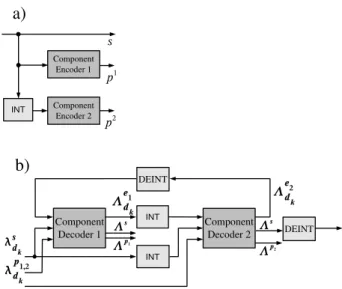
Fig. 1. (a)Turbo encoder,(b)Turbo decoder.
communications performance of the targeted communication system.
In Sect. 2 we summarize turbo encoding as well as the the principle of turbo code decoding. In the following Sect. 3 we explain the iterative synchronization and the interrelation with the decoding algorithm. In Sect. 4 we give an short overview about the target communication system and explain the use of trial frequencies for frequency offset estimation. Our proposed method for minimizing the number of trials to be performed is presented. In Sect. 5 we analyze the commu-nications performance of our proposed method. The hard-ware architecture is explained and hardhard-ware complexity of turbo synchronization without initial carrier synchronization is analyzed. Communications performance is determined by bit true models. Implementation complexities and results are given based on Xilinx devices. The paper is concluded in Sect. 6.
2 Turbo codes
With the introduction of binary turbo codes by Berrou in 1993 (Berrou et al., 1993) near optimum error correction be-came possible. Due to these error correction capabilities, binary and duo-binary turbo codes allow for low frame er-ror rates (FER) at a low signal-to-noise ratio (SNR), outper-forming the widely used convolutional codes. Because of this advantage turbo codes are now part of a large number of communication standards.
Turbo codes generally consist of a serial or parallel con-catenation of two codes, so called component codes, and an interleaver. While the first component code encodes the formation in the original order, the second one gets the in-formation in a permuted order, see Fig. 1a). In all standards convolutional codes are used as component codes.
Decoding of turbo codes is an iterative process where probabilistic information is exchanged between component decoders (Berrou, 2003). Iterative decoding implies a big challenge with respect to low latency and high throughput requirements.
A possible realization of a decoder for turbo codes is given in Fig. 1b). The two component decoders that decode the two component codes are connected via interleaver and deinter-leaver. They uselog likelihood ratios (LLR)λsd
k,λ p1 dk andλ
p2 dk of the systematic and parity information to compute the ex-trinsic information3ed1
k and3 e2
dkon the information bits. The iterative exchange of3ed1
k and3 e2
dkbetween these component decoders is referred to as turbo principle. One(full) iteration is done if Decoder 1 and Decoder 2 have run once. If only one decoder has calculated new information, we call this one half iteration.
Both component decoders optimize themaximum a poste-riori probability(MAP) criterion. However, in hardware im-plementations the suboptimal Max-Log MAP algorithm with extrinsic scaling factor(ESF) is more suitable. In compari-son to the optimal algorithm the Max-Log MAP results in a performance loss of less than 0.2 dB (Robertson et al., 1995, 1997). Furthermore, the Max-Log MAP algorithm does not require knowledge of the SNR in contrast to the optimal Log MAP algorithm (Worm et al., 2000).
The Max-Log MAP algorithm consists of a forward and a backward recursion. It computes for each possible informa-tion or parity bitdk ana posteriori probability(APP) LLR
3s,3p1,3p2.
3 Turbo synchronization
The synchronization consists of the estimation of the un-known parameters of timing, frequency and phase offset, and the elimination of all possible negative influences intro-duced by these parameters. We focus on the frequency and phase synchronization of bursts with linear modulation (e.g. QPSK,16-QAM) in conjunction with turbo decoding. We as-sume, that the steps of gain control, timing synchronization and burst detection are properly carried out before. The re-ceived sample sequenceris given in the complex baseband according to Eq. (1):
r(l)=s(l)·ej (2πfol+8)+n(l) l=0,1,...,L−1 (1)
The sample sequencer withLelements is based on modu-lation symbolss(l)with one sample per symbol and symbol durationT, and is disturbed by a noise sequencen. The un-known parameters of frequency offsetfo and phase offset
8have to be estimated for every received sample sequence. These parameters are considered fixed during an estimation interval; the sample sequence has to be corrected accordingly to the estimated frequency offsetf˜oand estimated phase
The synchronization with turbo synchronization is done in two main steps. Initially, a (coarse) carrier synchronization is performed. In case of larger variances of the estimation pa-rameters a degradation in the decoding performance will oc-cur. The principle of turbo synchronization is to improve the estimation parameters for synchronization (fine synchroniza-tion) with the additional use of tentative decoder decisions. The improved carrier synchronization is used to provide bet-ter input data for the decoding process. This process is done iteratively after each decoder iteration. We concentrate first on the step of fine synchronization, which will be used for turbo synchronization.
Frequency and phase offset can be optimally estimated on an unmodulated carrier. With the assumption, that the trans-mitted symbol sequencesof the burst is known the effect of the modulation by each transmitted symbols(l)can be re-moved by:
˜
r(l):=r(l)·s∗(l) l=0,1,...,L−1 (2) However, it must be considered, that usually the symbols of the burst are unknown or only some symbols, used for sup-porting the burst detection or supsup-porting the coarse synchro-nization are known. Thus we replace the transmitted symbol sequencesby an estimated symbol sequencese. The
estima-tion of the transmitted symbol sequence is provided by the turbo decoder.
The fine estimation of frequency and phase offset is based on the average phaseφ˜0of the front part and on the average
phaseφ˜1of the rear part of the burst with a modulation
re-moval by the estimated symbol sequencese. This is formally
given by
˜
φk:=
L/2−X1+k·L/2
l=0+k·L/2
r(l)·se∗(l) k=0,1 (3)
With the two phase values of Eq. (3) the estimate of the fre-quency offset can be calculated with
˜
f0=
arg(φ˜0· ˜φ1
∗
)
2π·L (4)
The estimate of the phase offset is calculated with the help of Eq. (4)
˜
φ=arg(φ˜0+ ˜φ1)−L· ˜f0·π (5)
The first decoder iteration is based on the LLR valuesλsd
k,
λpd1
k andλ p2
dk calculated with the symbols of the coarse syn-chronized received sequence. For the iterative fine syn-chronization an estimate of the transmitted symbols is used, which is produced by the turbo code decoder after each it-eration. The estimate of the transmitted symbols is gathered by the APP LLR of the decoder. A turbo code decoder com-putes APP LLR values3s of the systematic bits by default.
Fig. 2.Considered burst structure.
In turbo synchronization applications the decoder must addi-tionally calculate the APP LLR values3p1,2 for the parity bits.
To reduce the effect of using some erroneous reference symbols in the fine synchronization, soft values are used for the reference symbols. The values for the quadrature com-ponents of the estimated symbols are calculated by a tanh operation on the APP LLR. Provided that thek-th transmit-ted QPSK symbols(k)contains the bitsdk(I )anddk(Q)of the code word the estimated symbolse(k)is calculated as:
se(k)=tanh
3(dk(I ))
2 +jtanh
3(dk(Q))
2 (6)
With the tentative soft values of systematic bits and parity bits the sequenceseis generated and the described fine
syn-chronization process can be carried out.
The received sequence r is corrected with the new esti-mates of frequency and phase offset. A new synchronized received sequencer is calculated after each full decoder it-eration. Turbo decoding and fine synchronization run in par-allel in our architecture to avoid throughput degradation by turbo synchronization. For the n-th iteration of the decoder the LLR values3¯s,3¯p1, and3¯p2of the transmitted bits are
calculated on base of the fine synchronized sequence, which used the APP LLR values of the (n−2)-th iteration. A dis-cussion of the effects of the schedule regarding the update of LLR values can be found in Alles et al. (2007).
4 Evaluation of a grid of trial frequency offsets
In our targeted communication system the variance of fre-quency offset estimation with data aided estimation methods as well as with blind estimation methods is not sufficiently small to perform afterwards a turbo synchronization with sat-isfying communications performance. This is caused by the targeted SNR range below zero dB and the low number of symbols (known and unknown).
Thus a grid of trial frequency offsets is tentatively used. These trial frequency offsets are evaluated by the decoding to decide on the best estimation. The effort is now determined by the number of trial frequencies to be processed.
To perform synchronization and decoding a set of trial fre-quency offsetsf˜iis used. For using this method it is required to estimate a corresponding phase offsetφ˜ for each trial fre-quency offset. Applying the trial frefre-quency offset to to the received sequenceris given by:
rf˜i=r(l)·e−j ( ˜
fi·l) l=0,1,···L−1 (7) For maximum likelihood estimation of the phase offset the well known V&V algorithm (Viterbi and Viterbi, 1983) is used. A correlation of the modified received sequencerf˜i
with the unique word at the start and end of the burst is per-formed, which is given by:
kf˜i=
X
l∈U W
rf˜i(l)·u∗U W(l) (8)
The estimation of the phase offsetφ˜ for the trial frequency offset is given by the argument of the phasorkf˜iof Eq. (8):
˜
φfi=arg(kf˜i) (9) As mentioned a criterion is required to decide on the best frequency offset. The received sequencer will be corrected with the trial frequencyf˜i and the belonging phase offsetφ˜. Based on this new sequence the LLR values for the turbo decoder can be calculated. The decoder performs the iter-ations as described in Sect. 2. For a decision on the best trial frequency offset an estimationseof the transmitted
bol sequence is used. The estimate of the transmitted sym-bol sequence is achieved as described in Sect. 3. For every trial frequency the correlation of received symbol sequence
rand the estimated transmitted symbol sequenceseis used.
Correlation is a measurement of similarity and thus the trial frequency producing the greatest similarity between the two mentioned sequences is chosen. The correlation operation is given by
cf˜i=
LX−1
l=0
rf˜i(l)·se∗(l) (10)
The selection process is done with
˜
f= ˜fk with cf˜k≥cf˜i for all i (11)
For the selection process off˜it is sufficient to use the se-quence se in Eq. (11), which is achieved after one or two
turbo decoder iterations.
The computational effort for the evaluation of trial fre-quencies is dominated by the total number of turbo decoder iterations which must be performed. Thus it is desirable to minimize the number of trial frequency offsets to be evalu-ated by the decoder. The calculevalu-ated phasorkf˜ifor phase
esti-mation in Eq. (8) can be used to exclude trial frequency off-sets from consideration before the decoding step. The mag-nitude of the correlation is a measure for similarity and thus only trial frequency offsetsfiwith
|cf˜i|≥CT r (12)
will be processed. It must be emphasized, that the best esti-mation of the frequency offset is not given by the maximum correlation value of Eq. (8).
5 Results
Our approach for synchronization and decoding without ini-tial carrier synchronization is validated per software simula-tions with bit true models in sense of communicasimula-tions per-formance. In addition the architecture of the system is pre-sented. The complexity of the components for implementa-tion on Xilinx FPGA is shown and briefly analyzed.
5.1 Communications performance
The communications performance of our system is demon-strated for a burst with QPSK modulation. The start unique word and end unique word contains 40 and 24 symbols, re-spectively. The code word uses 1248 symbols; it is based on turbo encoding with rate 1/3 and 16 states. A grid of 61 trial frequencies is used for this burst type. The trial frequencies are chosen to cover the maximum relative frequency offset of 6×10⁻³and to allow a fine synchronization by the principle of turbo synchronization.
−1.4 −1.2 −1 −0.8 −0.6 −0.4 −0.2 0 10−4
10−3 10−2 10−1 100
Signal−to−noise−ratio E
S / N0
Frame Error Rate
Blind No Threshold 2800 3800 4800
Fig. 3.Communications performance.
−1.4 −1.2 −1 −0.8 −0.6 −0.4 −0.2 0
35 40 45 50 55 60 65
Signal−to−noise−ratio E
S / N0
Complexity in % of accepted frequencies Threshold 2800 Threshold 3800 Threshold 4800
Fig. 4.Trial frequencies evaluated by decoder.
With the threshold parameter a trade off between commu-nications performance and implementation performance can be regulated. The graphs with label “3800” and “4800” re-spectively show the FER performance for different values of the threshold. The computational effort for the differ-ent threshold values is shown in Fig. 4 as a percdiffer-entage of the number of considered frequency offset values. For the threshold label “3800” approximately 50% of the trial fre-quencies have to be evaluated. It is possible to choose the threshold value for a defined SNR operation point. This is demonstrated with the graphs with label “3800”. For SNR values above −0.2 dB the performance is identical to the method without threshold. Depending on the exact value of the threshold about 40% to 60% of the trial frequencies can be excluded before the decoding step.
Fig. 5.Architecture.
Table 1.Key parameter of the turbo decoder.
Binary Turbo decoder
Architecture Serial MAP, 3 ACS units
Trellis states 16
Infoword size 128–5124 bits
Codeword size 128–15 372 bits
Code rates 1/3...9/10
Parallelism 1
Input quantization 6 bit
Algorithm MaxLog-MAP
ESF 0.75
Max. iterations 8
Technology FPGA
Clock frequency 223 MHz
Payload Thrpt. [Mbit/s] 4.67–14.02
Latency [µs] 10.36–414.7
Payload Bit/Cycle 0.02–0.06
5.2 Architecture and implementation
The architecture of the system is depicted in Fig. 5. Ob-jective of the architecture is to allow a hardware sharing of functionalities of turbo synchronization and trial frequency processing. Central part is the MAP component, which per-forms a half iteration of turbo code decoding. Component Pre includes the frequency and phase correction of the re-ceived sequencer, which is used for the step of fine synchro-nization in turbo synchrosynchro-nization as well as for processing of trial frequencies. The phase estimation according to Eq. (8) for the processing of trial frequencies is also included in com-ponent Pre as well as the determination, whether the actual trial frequencyfi will be excluded. The calculation of LLR values including in the demapping and depuncturing is used for providing the input data for the MAP component.
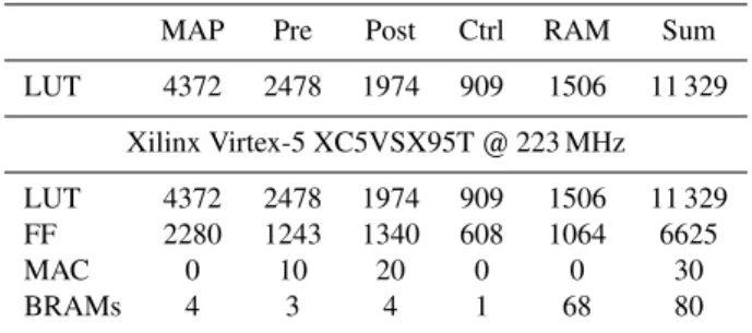
Table 2.Details of implementation complexity.
MAP Pre Post Ctrl RAM Sum
LUT 4372 2478 1974 909 1506 11 329
Xilinx Virtex-5 XC5VSX95T @ 223 MHz
LUT 4372 2478 1974 909 1506 11 329
FF 2280 1243 1340 608 1064 6625
MAC 0 10 20 0 0 30
BRAMs 4 3 4 1 68 80
values to symbols as described for QPSK symbols in Eq. (6). The small part for frequency and phase estimation accord-ing to Eqs. (4) and (5) in component Post is used only for fine synchronization. All shown RAM blocks are double buffered to allow a parallel processing of the main compo-nents. Therefore different trial frequencies are processed in the components Pre, MAP and Post. The step of fine syn-chronization is carried out in component Pre and Post on the results of iteration n, while the MAP decoder executes the iterationn+2.
The architecture of the turbo decoder is a state-of-the-art SMAP architecture with three recursion units which run in parallel. The key parameter are summarized in Table 1. For more details the reader is referred to May et al. (2007).
The resources for the components are presented in Table 2 for an implementation in a Xilinx Virtex-5 FPGA. Compo-nent Post is needed only for turbo synchronization and trial frequency evaluation respectively. Approximately half of the resources of component Pre are used for turbo synchroniza-tion and trial frequency evaluasynchroniza-tion, respectively.
6 Conclusions
In this paper we presented a novel method to reduce the com-plexity for turbo synchronization without initial carrier syn-chronization. To perform the decoding and synchronization steps without initial carrier synchronization a grid of trial fre-quencies is needed. The computational effort for process-ing of trial frequencies can be reduced by elimination of trial frequencies with a simple threshold comparison in the phase estimation step. Furthermore by applying turbo synchroniza-tion the grid of trial frequencies can be kept more coarse than with traditional decoding. The proposed hardware architec-ture allows a sharing of the components for evaluation of trial frequencies and for synchronization and decoding.
The components for trial frequency evaluation as well as for synchronization and turbo decoding can work concur-rently. The mentioned features result in a low complexity system. The achieved communications performance is com-parable to a system with perfect knowledge of the synchro-nization parameters.
References
Alles, M., Lehnigk-Emden, T., Wasenm¨uller, U., and Wehn, N.: Im-plementation Issues of Turbo Synchronization with Duo-Binary Turbo Decoding, in: Proc. 19th Annual IEEE International Sym-posium on Personal, Indoor and Mobile Radio Communications (PIMRC) 2007, Athens, Greece, 2007.
Berrou, C.: The Ten-Year-Old Turbo Codes are Entering into Ser-vice, IEEE Communications Magazine, 41, 110–116, 2003. Berrou, C., Glavieux, A., and Thitimajshima, P.: Near Shannon
Limit Error-Correcting Coding and Decoding: Turbo-Codes, in: Proc. 1993 International Conference on Communications (ICC ’93), pp. 1064–1070, Geneva, Switzerland, 1993.
May, M., Neeb, C., and Wehn, N.: Evaluation of High Throughput Turbo-Decoder Architectures, in: Proc. IEEE International Sym-posium on Circuits and Systems (ISCAS 2007), New Orleans, USA, 2007.
Mengali, U. and D’Andrea, A.: Synchronization Techniques for Digital Receivers, Plenum Publishing Corporation, New York, 1997.
Meyr, H., Moeneclaey, M., and Fechtel, S. A.: Digital Communica-tion Receivers, John Wiley & Sons Inc., 1998.
Robertson, P., Villebrun, E., and Hoeher, P.: A Comparison of Opti-mal and Sub-OptiOpti-mal MAP decoding Algorithms Operating in the Log-Domain, in: Proc. 1995 International Conference on Communications (ICC ’95), pp. 1009–1013, Seattle, Washing-ton, USA, 1995.
Robertson, P., Hoeher, P., and Villebrun, E.: Optimal and Sub-Optimal Maximum a Posteriori Algorithms Suitable for Turbo Decoding, European Transactions on Telecommunications (ETT), 8, 119–125, 1997.
Viterbi, A. J. and Viterbi, A. M.: Nonlinear Estimation of PSK Modulated Carrier Phase with Application to Burst Digital Transmission, IEEE Transactions on Information Theory, 32, 543–551, 1983.