Frame Detection For Synchronization In
OFDM
Rakhi Thakur,Kavita Khare
Department of electronics,MANIT,Bhopal
[email protected] [email protected]
MANIT,Bhopal,INDIA
Abstract—Orthogonal frequency division multiplexing (OFDM) is a parallel transmission scheme for transmitting data at very high rates over time dispersive radio channels and sub carriers are used to carry that data. These subcarriers are orthogonal to each other. In an OFDM system, frame
synchronization and frequency-offset estimation are extremely important for maintaining orthogonality among these subcarriers. The Frame detection is the task of finding an approximate estimate of the start of the preamble of an incoming packet. As such it is the first synchronization algorithm that is performed, so the rest of the synchronization process is dependent on good packet detection performance. By using Xilinx software and verilog coding, in this paper the problem of frame detection is considered.
Keywords—Narrow band interference (NBI), Fast Fourier Transform (FFT), Inter Block Interference
(IBI),Inter-carrier interference(ICI),Carrier Frequency Offset(CFO).
I. Introduction
Orthogonal frequency-division multiplexing (OFDM) is a multi-tone technique for broadband digital transmissions. Its success in the communication industry is by the wide range of commercial applications, including the digital video broadcasting, the IEEE 802.11 wireless local area network and the digital subscriber line .Its inherent flexibility in sub-carrier assignment and power allocation, OFDM is currently considered as a powerful technology for supporting high-rate transmissions in hostile environments characterized by the presence of narrowband interference (NBI). A major disadvantage of OFDM is the remarkable sensitivity to synchronization errors. As is known, a carrier frequency offset (CFO) between the receiver and the transmitter destroys the subcarrier orthogonality and produces inter-carrier interference (ICI), while timing errors generates ICI as well as inter block interference (IBI). For these reasons, the synchronization problem in OFDM has received a great deal of attention in recent years.
II. The System Model
A. Structure Of IEEE802.11a
There is a standard preamble at the start of every frame according to the standard of IEEE802.lla. It is easy to see from Figure 1 that the preamble contains 10 identical short training symbols (each consists of 16 sampled data), 2 identical long training symbols (each contains 64 sampled data) and guard interval (each contains 32 sampled data). These symbols are used for frame synchronization, AGC; carrier frequency offset estimation, symbol timing synchronization and channel estimation [1].
Fig 1. The preamble structure of IEEE802.lla
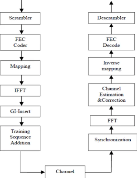
B. The base band system model of IEEE802.11a
Figure 2 describes the functional blocks for the transmitter and the receiver of the IEEE802.11a base band system. The OFDM symbol defined in the IEEE802.11a is composed of 48 mapped complex valuers,4 pilot signals and 12 zero signals, so the size of fast Fourier transform(FFT) and inverse FFT(IFFT) is 64. The guard Rakhi Thakur et al. / International Journal of Engineering Science and Technology (IJEST)
interval (GI) is used to avoid inter-symbol interference (ISI), and the length of the GI is 16 samples. One of the purposes of the preamble preceding every OFDM packet is to allow start-of-symbol detection. Using the fact that it is based on well-known patterns, which the receiver can recognize. The beginning of the preamble is based on “STS”, while the end is based on “LTS”. The reason why the short training symbols are only 16 samples long is due to the frequency domain sequence on which they are based, where every fourth carrier carries data while all the others do not. The result of the IFFT of such a sequence is that the 64 time domain samples can be split in 4 identical sub-symbols or 4 STS’s[6].
Fig 2. Base band system model of IEEE802.11a
III. Algorithm Of Frame Synchronization
The first task that an OFDM receiver must accomplish at start-up is frame detection. Frame detection is the task of finding an approximate estimate of the start of the preamble of an incoming packet. It is the first data-processing block of 802.11a base band receiver As such it is the first synchronization algorithm that is performed, so the rest of the synchronization process is dependent on good packet detection performance. Structure of the WLAN preamble enables the receiver to use a very simple and efficient algorithm to do frame detection, and frequency synchronization. This operation involves monitoring the received signal until the presence of a frame is revealed. When this occurs, a sync flag is generated and a timing acquisition procedure is initiated to establish the correct position of the Fast Fourier transform (FFT) window. Since the CFO is usually unknown in this initial phase, it is desirable that the timing recovery scheme may cope with possibly large frequency offsets. In commercial OFDM systems, a training symbol exhibiting a repetitive structure in the time-domain is used to mark the frame beginning and robust timing synchronization is achieved by searching for the peak of the correlation among the repetitive parts. This approach was originally proposed by Schmidl and Cox (SC) in [2], where a pilot symbol made of two identical halves are exploited for both timing and frequency acquisition. The main drawback of this method is that the corresponding metric exhibits a large plateau, which causes some uncertainty in determining the start of the frame. This problem is alleviated by designing training symbols that result into sharper timing metric trajectories. Solutions in this sense are proposed in [2],[3] and [4], where the pilot symbol is composed of several identical parts with possible sign inversions. An alternative approach for timing recovery capitalizes on the inherent correlation between the cyclic prefix (CP) and the last portion of the OFDM symbol [5].
IV. Mathematical analysis
Initially a frame synchronization circuit is required to detect the frame starting point. This is usually achieved by correlating the incoming signal with a known preamble. The same circuit is sometimes used to adjust for initial gain control. Therefore, the threshold of the detection circuitshould be adjusted accordingly. Since timing offset does not violate orthogonality of the symbols it can be compensated after the receiver FFT. Packet detection is the task of finding an approximate estimate of the start of the preamble of an incoming data packet. As such it is the first synchronization algorithm that is performed, so the rest of the synchronization process is dependent on good packet detection performance [7]. Generally packet detection can be described as a binary hypothesis test. The test consists of two complementary statements about a parameter of interest. These
Rakhi Thakur et al. / International Journal of Engineering Science and Technology (IJEST)
statements are called the null hypothesis, HO, and the alternative hypothesis, H1.The test is set up as shown below.
HO: Packet not present H1: Packet Present
The actual test is usually of the form that tests whether a decision variable rn exceeds a predefined threshold Th. The packet detection case is shown below.
HO: rn <Th => Packet not present. H1:rn≥Th=>Packet Present.
The preamble of IEEE 802.11a standard has been designed to help detect the starting edge of the packet. This method, also called the Delay and Correlate Algorithm, takes advantage of the periodicity of the short training symbols at the start of the preamble. The simplest algorithm for finding the start edge of the incoming packet is to measure the received signal energy. When there is no packet being received, the received signal rn consists only of noise rn = wn. When the packet starts, the received energy is increased by the signal component rn = sn + wn, thus the packet can be detected as a change in the received energy level. The decision variable rn is then the received signal energy[8]. Fig 3 showsthe block diagram of the algorithm. Decision statistic rnusing the short training sequence with 0-dB SNR. The packet was set to start at n = 400 and the window length is 22, threshold can be taken within 10 to 35, in order to satisfy the IEEE 802.11a requirements. The low level of rn before the start of the packet is straight forward; when the received signal consists of only noise, the delayed cross-correlation is zero-mean random variable, since the noise samples are independent and thus uncorrelated. Once the start of the packet is received, the cross-correlation of the periodic short training symbols causes rn to jump to the maximum value. This jump gives quite a good estimate of the start of the packet.
Fig.3 Structure of the Frame Detector
\
V. Simulation Results:
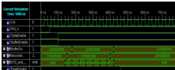
Using Xilinx software, the performance of OFDM system was tested. From the simulation results, it is observed that this algorithm allows good synchronization. From the results, it is observed that Total memory usage is 156984 kilobytes, Minimum period is 4.191ns (Maximum Frequency: 238.607MHz) and it provides the low area and high speed implementation of OFDM synchronizer.
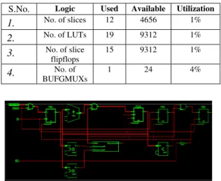
TABLE I FPGA resource utilization
S.No. Logic Used Available Utilization
1. No. of slices 12 4656 1%
2. No. of LUTs 19 9312 1%
3. No. of slice
flipflops
15 9312 1%
4. No. of
BUFGMUXs
1 24 4%
Fig 4 RTL view of Frame Detector Delay
Correlator Peak search
Y (k)
Rakhi Thakur et al. / International Journal of Engineering Science and Technology (IJEST)
Fig 5 Simulation waveform
VI. Conclusion
There is a constant requirement for efficient use of FPGA resources where occupying less hardware for a given system. This paper presents frame detection algorithm by which we can find out the start position of FFT. The FPGA solution offers complete flexibility in the design. By reducing chip count, it improves the overall reliability of the system, provides low area, low power and high-speed implementation of OFDM synchronizer.
REFERENCES
[1] Sun Wensheng Zhang Yuanyuan “A Frame Synchronization and Symbol Timing Synchronization Algorithm in BurstOFDM
Communication Based on IEEE802.11a”, International Forum on Information Technology and Applications IEEE 2009.
[2] T. Schmidl and D. Cox, “Robust frequency and timing synchronization for OFDM,” IEEE Trans. Communication, vol. 45, no.12,
1997:1613-1621
[3] H. Minn, M. Zeng, and V. K. Bhargava “On Timing Offset Estimation for OFDM Systems” IEEE COMMUNCATIONS LETTERS,
VOL. 4, NO. 7, JULY 2000.
[4] Byun 'oon Park, Hyunsoo Cheon, Changwn Kang, and Daesik Hong “A Novel Timing Estimation Method for OFDM Systems”
IEEE,2002.
[5] Seung Duk choi jung Min Choi and Jae Hong Lee “An initial timing offset estimation method for OFDM Systems in rayleigh fading
channel”2006 IEEE.
[6] Sun Wensheng Zhang Yuanyuan “A Frame Synchronization and Symbol Timing Synchronization Algorithm in Burst OFDM
Communication Based on IEEE802.11a ,IEEE 2009.
[7] Michail Segkos a thesis report on “Advanced techniques to improve the Performance of ofdm wireless lan”2004
[8] OFDM wireless LANs, a theoretical guide by Juha Heiskal and John Terry.
Rakhi Thakur et al. / International Journal of Engineering Science and Technology (IJEST)