S
EISMIC PERFORMANCE OF MASONRY
-
INFILLED
RC
FRAMES
Mircea BÂRNAURE
Lecturer, PhD, Faculty of Civil, Industrial and Agricultural Buildings Technical University of Civil Engineering Bucharest, Romania, e-mail: mircea. barnaure@utcb. ro
Ana-Maria GHIŢĂ
Lecturer, PhD, Faculty of Civil, Industrial and Agricultural Buildings Technical University of Civil Engineering Bucharest, Romania, e-mail: ana. ghita@utcb. ro
Daniel Nicolae STOICA
Assoc. Professor, PhD, Faculty of Civil, Industrial and Agricultural Buildings Technical University of Civil Engineering
Bucharest, Romania, e-mail: stoica@utcb. ro
Abstract. The masonry infill of RC frames structures is generally considered as non-structural. The design of the concrete frames is often made by ignoring the influence of the masonry infill, which is only accounted for its mass. The experience on buildings submitted to earthquakes shows that masonry infill walls completely change the behaviour of bare frames due to increased initial stiffness and low deformability. The way in which masonry infills affect the RC frames members is difficult to predict, as different failure modes can occur either in the masonry or in the surrounding frame. In addition to local effects, the position of the masonry infills at different levels can lead to structural irregularity, with a strong influence on the global seismic response of the building. Less infilled stories, also called soft stories, have a particularly unfavourable behaviour under seismic loads, as frame members at these levels are more susceptible to failure. This paper analyses the differences in the behaviour of bare and infilled frames through numerical modelling. Nonlinear push-over analyses of infilled frames are carried out under in-plane vertical and lateral loading. The infill panels are modelled as equivalent single diagonal struts. Several force-displacements laws are considered for these diagonals.
Key words: soft story, capacity curves, nonlinear analysis.
1. Introduction
Frame structures with infill masonry panels are a very common and used type of
The general design practice considers the infill masonry panels as non-structural elements. Neglecting the influence of the infills is dangerous, as they may highly modify the response of the structure, with unfavourable consequences (Uva et al., 2011; Kaushik et al., 2006):
− seismic forces acting on the infilled structures can differ from those acting on bare frames due to increased stiffness and decreased vibration period;
− torsional effects may appear as a
consequence of the asymmetrical position of the masonry panels;
− increased or different types of stresses can appear in the frame members;
− soft-storey mechanisms can appear due
to the uneven distribution of masonry panels along the height of the building.
The degradation of stiffness and strength capacity under cycling loading can lead to a general poor seismic performance (Paulay and Priestley, 1992).
The uncontrolled interactions between masonry and frames, and in particular soft storey configurations can lead to premature failure (Kirac et al., 2011). Premature failure can also occur if the masonry panels damage the concrete columns. In this scenario, a progressive collapse mechanism could be triggered (Marchis et al., 2013).
Even if unreinforced masonry has a brittle behaviour and low resistance to seismic actions, experimental studies show that masonry infills can have a
favourable influence on reinforced
concrete frame structures (Zovkic et al.,
2013, Kakaletsis and Karayannis, 2008). Infilled frames are stiffer and stronger and dissipate more energy than the corresponding bare frames (Crisafulli et al., 2000; Schwarz et al., 2015; Basha and Kaushik, 2016).
Full scale testing is expensive and time consuming and it does not always allow identifying correlations between the different parameters that influence the failure pattern (Turgay et al., 2014).
For this reason, many attempts at creating analytical or numerical models that allow predicting the infilled frames behaviour have been made since 1960. There are two types of analysis methods, each having some advantages and drawbacks (Fiore et al. 2012; Shing and Stavridis, 2014). The first method consists in representing the infill walls by equivalent diagonal struts. The second method consists in using refined finite element models.
In this paper the equivalent diagonals method is used. The scope is to draw conclusions regarding the behaviour of
infilled frames using the simplest
modelling technique. This type of models can, to some extents, be used by practicing engineers for current building design. As many earthquake design codes have no clear rules regarding the modelling of the infills, this paper aims to give practitioners simple rules for structural analysis of infilled frames under earthquake loads.
2. Overview of the numerical model
2. 1. Configuration of the model
The frame elements are made of concrete
class C20/25, reinforced with
longitudinal and transversal PC52
profiled steel bars, with fyd = 300 MPa. The cross-section of the column is 40x40 cm, reinforced with 8d20 and 4d25 bars. The beams are 25x45cm, with 3d16 as top and bottom reinforcement.
Masonry infills are considered to be made of solid clay bricks, with 25 cm thickness. The masonry unit’s compressive strength
is chosen as 15N/mm2 and the
compressive strength of the cement mortar is chosen as 10N/mm2.
The vertical and horizontal loads are applied as distributed on each beam. The chosen value for the vertical loads at each level is 50 kN/m. The lateral forces have an inverted triangular distribution. Nonlinear hinges are assigned to the beams and columns (P-M hinges).
2. 2. Capacity curves for the masonry infills
Three types of models were considered for the non-linear behaviour of the compressive diagonal struts. These models are mainly based on the American code FEMA-306, 1998, the Romanian design code P100/1-2013, and the equations proposed by Fardis and Panagiotakos, 1997.
The first model, further referred to as M1, is based on the FEMA-306, 1998 equations for quantifying the stiffness, the strength and the deformation capacity of the infill panels.
The effective width of the diagonal compression strut is:
(
)
inf4 . 0 1 175 .
0 h r
a= ⋅ λ ⋅ col − ⋅
where 4 1 inf inf 1 4 2 sin ⋅ ⋅ = h I E t E col fe me θ λ
hcol = column height between the centers of the beams;
rinf = diagonal length of the infill panel; Eme= modulus of elasticity which can be taken equal to 550fm, with fm being the compression strength of the masonry tinf =thickness of the infill panel and diagonal strut
Efe = modulus of elasticity of the frame material (concrete)
Icol = modulus of inertia of the columns hinf = height of the infill panel
The general shear failure of the panel can be defined in two steps, the initial and final contributions of shear carried by the infill panel being:
'
2 me vh
mi A f
V = ⋅
mi
me V
V =0.3⋅
Vmi = available initial shear capacity Vme = final shear capacity as a result of cyclic loading effects
Avh = net horizontal shear area of the infill panel
These equations lead to the following results: a = 0. 52 m
fme = 3. 075 N/mm2 Eme= 3214. 25N/mm2 Vmi= 157. 9 kN Vmf= 47. 4 kN
The value of the compression forces in the diagonal associated with Vmi and Vmf, Pmi and Pmf are:
Pmi= 197. 4 kN Pmf= 59. 2 kN
The nonlinear deformation capacities of the infills, expressed in terms of story drift ratio percentages, were considered 0. 6% for Life Safety Performance Level and 2. 5% for collapse.
represented by a linear law, with four branches (Fardis and Panagiotakos, 1997). The width of the diagonal strut is chosen as equal to 10% of its length.
For the M2 model, the force-displacement law was chosen as follows. The maximum strength of the diagonal strut was computed using the formulas from the Romanian seismic design code P100/1-2013. The failure of the infill corresponds to the crushing of the compressed diagonal for the force value:
pan pan
dh
Rd f A k
F ,32 = ⋅ ⋅ 4,
where fdh is the design compressive strength of masonry parallel to the bed joint, Apan is the area of masonry panel and k4,pan is a coefficient that takes into account the geometry of the panel.
The first branch, corresponding to the initial stiffness of the diagonal, has the limit Fcr. Fcr was chosen as 0. 55 of the maximum force based on results from tests on infilled frames (Dolsek and Fajfar, 2008). The drift ratio corresponding to the maximum load was chosen as equal to 0. 25% based on experimental tests (Chen et al., 2008; Stavridis et al., 2012).
After peak force is reached, further displacement leads to a decrease of the force, down to the residual strength FU. The displacement corresponding to FU is assumed to be five times larger than at maximum force. FU is considered to be 20% of the maximum strength, based on results of full scale tests (Dolsek and Fajfar, 2008; Lee and Woo, 2002).
With the above assumptions:
Fmax= FRd, 32 = 222 kN
Fcr = 122 kN FU = 44. 4kN
For the M3 model, the first branch of the law is given by the initial stiffness of the
masonry infill (Kel) and limited by the shear cracking strength:
w w w w el h l t G K = ⋅ ⋅
w w tp cr f t l
F = ⋅ ⋅
Gw is the elastic shear modulus of the masonry, tw and lw are the thickness and the length of the panel, ftp is the shear cracking stress.
The second branch of the M3 model is given by the stiffness of the masonry and the maximum strength:
w w w m d t b E Ksec = ⋅ ⋅
cr
F Fmax =1.30⋅
Em is the elastic modulus of the masonry, bw and dw are the width and the length of the diagonal strut.
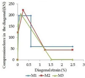
Fig. 1. Considered force-strain curves for the equivalent diagonal struts
The third branch corresponds to the behaviour of the infill after cracking. The stiffness after degradation and the residual strength are:
el soft K
K =−α⋅
cr
U F
F =0.01⋅
The parameter α was chosen 0. 01.
The following values were obtained, for the M3 model:
Fcr = 158kN
Ksec = 146102kN/m Fmax = 205kN
Ksoft =14610kN/m FU=2kN
The three considered force strain curves are shown in Fig. 1. For all the models, the maximum strain was limited to 2. 5%.
3. Results
3. 1. Failure modes
For all the considered configurations, collapse corresponds to the failure of the ground floor columns under combined axial and bending stresses. The presence of the infills alters the behaviour of the structure. For the bare frame situation (Fig. 2) plastic hinges develop at all the beams ends. Only after important deformations occur in the beams (red and purple colour of the plastic hinges) is collapse attained.
Fig. 2. Deformed shape at final step for bare frame structure (5 bays)
Fig. 3. Deformed shape at final step for fully infilled frame structure (5 bays)
For the fully infilled structure (Fig. 3) fewer plastic hinges form at beams ends and their
stress level at collapse is lower. For the soft story configuration (Fig. 4) even fewer plastic hinges form, which means that this type of structure has low ductility.
Fig. 4. Deformed shape at final step for soft story configuration (5 bays)
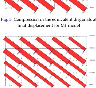
Regarding the forces that develop in the diagonals, a certain difference is observed between model M1 (Fig. 5) and model M2 (Fig. 6). Model M3 is similar to model M2.
Fig. 5. Compression in the equivalent diagonals at final displacement for M1 model
Fig. 6. Compression in the equivalent diagonals at final displacement for M2 model
and M3 models, many diagonals display lower forces, as their strain is higher than that corresponding to the peak value.
3. 2. Building stiffness
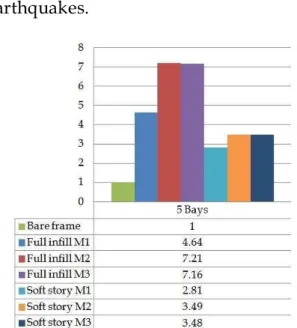
For all the analysed configurations, the presence of masonry infills leads to an increase of the building stiffness. This change in stiffness can lead, depending on the design response spectrum, to
higher peak acceleration during
earthquakes.
Fig. 7. Increase in stiffness of the structure when compared to the bare frame situation (5 bays)
Fig. 8. Increase in stiffness of the structure when compared to the bare frame situation (3 bays)
The ratios between the initial stiffness of a certain configuration and the stiffness
of the corresponding bare frame are shown in Fig. 7 and Fig. 8 for 5 and 3 bays structures respectively. The value of these ratios ranges from 2. 79 up to 7. 21.
3. 3. Lateral story drifts
The increase in stiffness is accompanied by lower values of the story drifts at ultimate displacement, in particular for the upper stories.
The r atios betwee n the maximum story drift for a given configuration and the maximum drift of the same story for the corresponding bare frame are shown for 3 bays str uctures in Fig. 9 and Fig. 10.
Fig. 9. Influence of the infills on the deformed shape of the building (based on the relative value
of story drifts) for 3 bays fully infilled structures
As the drift ratios are not similar for all the stories, it means that the infills modify the deformed shape of the building, and therefore the value and distribution of stresses between frame members.
The ratios between the current story and the ground floor drift for 3 bays configurations are shown in Fig. 11 and Fig. 12. For the bare frame structure,
similar lateral displacements are
display much lower drifts for 2nd and 3rd floor, with ratios as low as 0. 035.
Fig. 10. Influence of the infills on the deformed shape of the building (based on the relative value
of story drifts) for 3 bays soft story structures
Fig. 11. Influence of the infills on the deformed shape of the building (based on the normalized values of story drifts) for 3 bays configurations
This explains the differences of the plastic hinges at maximum displacement seen in figures 5, 6 and 7.
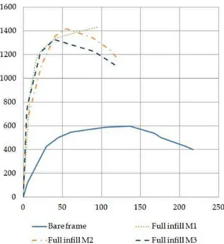
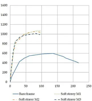
3. 4. Force-displacement curves
The force-displacement curves for the analysed structures are shown in Fig. 13 and Fig. 14 for 5 bays configurations and in Fig. 15 and Fig. 16 for 3 bays configurations.
All the infilled structures display higher
maximum base shear, but lower
maximum displacement. The three
modelling assumptions lead to similar results. A slight difference is observed in Fig. 13 between the M1 and the other two models. This is due to the fact that in the M2 and M3 models, after reaching maximum value, the force in the diagonals diminished for further lateral displacement.
Fig. 12. Influence of the infills on the deformed shape of the building (based on normalized values of drifts) for 3 bays soft story structures
Fig. 14. Base shear (kN) vs. displacement (mm) for bare frame and soft story configurations (5 bays)
Fig. 15. Base shear (kN) vs. displacement (mm) for bare and fully infilled frames (3 bays)
Fig. 16. Base shear (kN) vs. displacement (mm) for bare frame and soft story configurations (3 bays)
The number of bays does not seem to have a strong influence on the general behaviour of the structures. For both the fully infilled and soft-storey configurations, the final displacement is equal to approximately 50% of the maximum displacement of the bare frame.
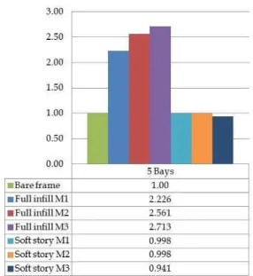
3. 5. Dissipated energy
The area under the force-displacement curves previously shown represents the energy dissipated by the building. The ratios between the input energy that leads to collapse and the input energy
that leads to collapse for the
corresponding bare frame are shown in Fig. 17 and Fig. 18 for 3-bays and 5-bays configurations respectively.
Fig. 17. Ratio between the input energy that leads to collapse for a given configuration and for the
corresponding bare frame (5 bays)
Fig. 18. Ratio between the input energy that leads to collapse for a given configuration and for the
corresponding bare frame (3 bays)
Fig. 19. Ratio between the input energy for which the building shows no damage and the matching
energy for the bare frame (5 bays)
The computed energy for the soft-storey configurations is practically identical to the corresponding energy for the bare frame. The computed energy for the fully infilled configurations is much higher (up to 2. 7 times) than that of the non-infilled situation.
4. Conclusions
The numerical simulations show that masonry infills alter the seismic behaviour of reinforced concrete frames. The considered diagonal force-strain curves
lead to similar results for the building behaviour under combined in-plane vertical and lateral loads. The number of bays seems to have no influence on the structural behaviour. For all the analysed situations, masonry infills determined an increase in stiffness for the building and lower maximum story drifts.
Fig. 20. Ratio between the input energy for which the building shows no damage and the matching
energy for the bare frame (3 bays)
In terms of energy, fully infilled frames showed a much better behaviour than the bare frames. Firstly, the input energy for which the building shows no damage is 2 to 2. 7 times higher. This means that for low or moderate earthquakes, fully infilled frames are less susceptible to be damaged. As to the input energy required to reach the collapse of the structure, fully infilled frames also performed better, with an increase between 12% and 48% of the energy when compared to the bare frame situation.
Soft storey configurations required
configurations are unfavourable and require a particular care during design, as to avoid premature collapse of the buildings during strong earthquakes.
REFERENCES
Basha S., Kaushik H. (2016), Behavior and failure mechanisms of masonry-infilled RC frames (in low-rise buildings) subject to lateral loading, Engineering Structures 111: 233-245. Chen S-Y., Moon F.L., Yi T. (2008), A macroelement for
the nonlinear analysis of in-plane unreinforced masonry piers, Engineering Structures 30(8): 2242-2252.
Crisafulli F.J., Carr A.J., Park R. (2000), Analytical modelling of infilled frame structures-a general review, Bulletin-New Zealand Society for Earthquake Engineering 33(1): 30-47. Dolsek M., Fajfar P. (2008), The effect of masonry infills
on the seismic response of a four-storey reinforced concrete frame – a deterministic assessment, Engineering Structures 30: 1991-2001. Fardis M. N., Panagiotakos T. B. (1997), Seismic design
and response of bare and masonry-infilled reinforced concrete buildings part II: infilled structures, Journal of Earthquake Engineering
1(3): 475-503.
FEMA-306 (1998), Evaluation of Earthquake Damaged Concrete and Masonry Wall Buildings–Basic Procedures Manual, FEMA, Washington DC. Fiore A., Netti A., Monaco P. (2012), The influence
of masonry infill on the seismic behaviour of RC frame buildings, Engineering Structures
44: 133-145.
Kakaletsis D.J., Karayannis C.G. (2008), Influence of masonry strength and openings on infilled R/C frames under cycling loading, Journal of Earthquake Engineering 12(2): 197-221. Kaushik H., Rai D., Jain S. (2006), Code Approaches to
Seismic Design of Masonry-Infilled Reinforced ConcreteFrames: A State-of-the-Art Review, Earthquake Spectra 22(4): 961-983.
Kirac N., Dogan M., Ozbasaran H. (2011), Failure of weak-storey during earthquakes, Engineering Failure Analysis 18(2): 572-581.
Lee H.-S., Woo S.-W. (2002), Effect of masonry infills on seismic performance of a 3 storey R/C frame with non seismic detailing, Earthquake engineering & structural dynamics 31(2): 353-378. Mainstone R. J. (1971), On the Stiffnesses and
Strengths of Infilled Frames, Proceedings of the Institution of Civil Engineers, Supplement IV, pp. 57-90.
Marchis A., Moldovan T., Ioani A. (2013), The influence of the seismic design on the progressive collapse resistance of mid-rise RC framed structure, Acta Tehnica Napocensis: Civil Engineering & Architecture 56(2): 222-234. P100-1/2013 (2013) Code for seismic design – Part I –
Design prescriptions for buildings [in Romanian], Ministry of Regional Development and Public Administration, Bucharest, Romania.
Paulay T., Priestley M.J.N. (1992), Seismic Design of Reinforced Concrete and Masonry Buildings, John Wiley & Sons, Inc., New York
Schwarz S., Hanaor A., Yankelevsky D.Z. (2015), Experimental Response of Reinforced Concrete Frames With AAC Masonry Infill Walls to In-plane Cyclic Loading, Structures
3: 306-319.
Shing P., Stavridis A. (2014), Analysis of seismic response of masonry-infilled RC frames through collapse, ACI Structural Journal 297: 1-20. Stavridis A., Koutromanos I., Shing P.B. (2012),
Shake table tests of a three story reinforced concrete frame with masonry infill walls, Earthquake Engineering & Structural Dynamics 41(6): 1089-1108.
Turgay T., Durmus M., Binici B., Ozcebe G. (2014), Evaluation of the Predictive Models for Stiffness, Strength, and Deformation Capacity of RC Frames with Masonry Infill Walls, Journal of Structural Engineering 140(10): 06014003. Uva G., Porco F., Fiore A. (2012), Appraisal of
masonry infill walls effect in the seismic response of RC framed buildings: a case study, Engineering Structures 34(1): 514-526. Zovkic J., Sigmund V., Guljas I. (2013), Cyclic
testing of a single bay reinforced concrete frames with various types of masonry infill, Earthquake engineering & structural dynamics 42(8): 1131-1149.
Received: 11 April 2016 • Revised: 26 April 2016 • Accepted: 27 April 2016