Submitted 29 May 2015
Accepted 10 August 2015
Published26 August 2015
Corresponding author Giovanni Beltrame,
giovanni.beltrame@polymtl.ca
Academic editor Mary Sheeran
Additional Information and Declarations can be found on page 16
DOI10.7717/peerj-cs.21 Copyright
2015 Beltrame
Distributed under
Creative Commons CC-BY 4.0
OPEN ACCESS
Triple Modular Redundancy verification
via heuristic netlist analysis
Giovanni Beltrame
Polytechnique Montr´eal, Montr´eal, Qu´ebec, Canada
ABSTRACT
Triple Modular Redundancy (TMR) is a common technique to protect memory elements for digital processing systems subject to radiation effects (such as in space, high-altitude, or near nuclear sources). This paper presents an approach to verify the correct implementation of TMR for the memory elements of a given netlist (i.e., a digital circuit specification) using heuristic analysis. The purpose is detecting any issues that might incur during the use of automatic tools for TMR insertion, optimization, place and route, etc. Our analysis does not require a testbench and can perform full, exhaustive coverage within less than an hour even for large designs. This is achieved by applying a divide et impera approach, splitting the circuit into smaller submodules without loss of generality, instead of applying formal verification to the whole netlist at once. The methodology has been applied to a production netlist of the LEON2-FT processor that had reported errors during radiation testing, successfully showing a number of unprotected memory elements, namely 351 flip-flops.
Subjects Computer Aided Design, Computer Architecture, Embedded Computing
Keywords Single event effects, Triple Modular Redundancy, Verification
INTRODUCTION
At high altitude or in space, without the protection of the earth’s magnetic field and atmosphere, integrated circuits are exposed to radiation and heavy ion impacts that can disrupt the circuits’ behavior. This paper focuses on Single-Event-Upsets (SEUs), or soft errors, usually caused by the transit of a single high-energy particle through the circuit. In particular, we consider single bit flips in memory elements embedded in logic, implemented as flip-flops. Protection against SEUs can be obtained in several ways, and in particular this work considers the protection strategy based on the triplication of the storage elements of a circuit, combined with majority voting (Carmichael, 2006), usually referred to as Triple Modular Redundancy (TMR).
software (Kanawati & Abraham, 1995;Bou´e, P´etillon & Crouzet, 1998;Maestro, 2006;
Goswami, Iyer & Young, 1997) and hardware-based (Aguirre et al., 2005) tools for fault injection and protection verification have been proposed in the recent past. However, such tools usually are not designed to provide full SEU protection verification, and require extremely long simulation and/or execution times when attempting comprehensive fault injection and analysis campaigns. To the best of the author’s knowledge, no commercial or academic tool providing TMR implementation verification is currently available.
This paper presents a novel way to verify the TMR implementation of a given circuit by executing a heuristic netlist analysis. Our goal is to verify that TMR constructs are insensitive to single bit flips (i.e., the logic is triplicated), and transients on clock or reset (i.e., there are no common reset/clock lines between redundant memory elements). To reduce execution time, we use adivide et imperaapproach, splitting the netlist in smaller submodules, without loss of generality. Results show that verifying TMR on a 40k gates netlist is possible within around half an hour on a standard PC. As this work is based on formal analysis, our approach does not rely on a testbench, allowing a full coverage test based solely on the device netlist.
This paper is organized as follows: previous works on the subject are introduced in ‘Previous Work’; ‘Proposed Approach’ details the algorithm together with necessary definitions, its implementation and its complexity; experimental results are shown in ‘Ex-perimental Results’, and ‘Conclusions and Future Work’ draws some concluding remarks.
PREVIOUS WORK
In the past, different approaches have been proposed for design verification against soft errors. These approaches can be divided in two kinds: fault injection simulation and formal verification.
Formal verification against soft-errors was introduced by (Seshia, Li & Mitra, 2007): the idea is to merge a formal model of the DUT with a soft error model, proving a given set of properties on the merged model. This requires a formal model of the DUT and a complete and exhaustive set of formally defined properties to be proven. In other words, the main issue of this formal approach is that the coverage is as good as the definition of such properties.
This work tries to overcome these limitations and provide full verification of a TMR-based DUT with reasonable analysis time. The idea presented in this paper can be classified as a fault-injection simulation, but follows a different approach as compared to previous work: instead of trying to simulate the whole circuit at once and doing a timing accurate simulation, we focus on a behavioral, timeless, simulation of small submodules, extracted by automatic analysis of the DUT internal structure, with the specific goal of detecting any triplicated FF that is susceptible to the propagation of SEUs in the DUT.
PROPOSED APPROACH
The starting point of our analysis is a radiation hardened circuit, protected by triplication of storage elements and voting (TMR inCarmichael (2006)). Our objective is to verify that indeed all FFs are adequately protected, and no issues were introduced, for example, by synthesis or routing tools.
Starting from a given design withnFFs, a naive testing approach for SEU-sensitive FFs would require injecting faults in all 2npossible FF configurations, for all of themtime instants of a given testbench. This would lead to an impractically long simulation time, as typical systems consist of several thousand FFs. Our approach performs a behavioral fault injection, splitting the whole system into smaller submodules, that can be analyzed independently, allowing full verification to be carried out in a reasonable timeframe.
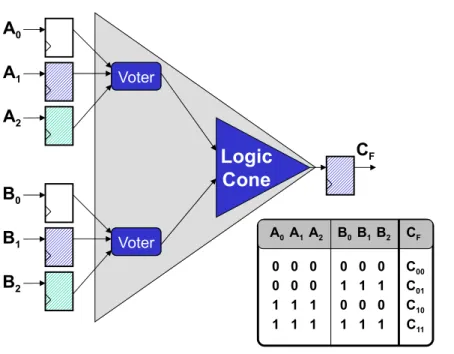
These submodules are thelogic conesdriving each FF. A logic cone is a set of com-binational logic bounded by FFs and I/O (seeFig. 1). To verify that no FF are sensitive to SEUs (therefore assuring the correct TMR implementation), it is possible to extract its driving logic cone, and perform an exhaustive fault injection campaign. This means that the FFs bounding the logic cone are injected single bit flips in all possible input configurations, comparing the output of the logic cone with its expected (i.e., fault-free) one. It is also necessary to verify that all the triplicated FFs have separate asynchronous reset and set lines, otherwise a transient on one of these lines might still cause a failure in the circuit. Testing all possible configurations for a logic cone means 2nf injections, with
nf the number of driving flip-flops making the analysis difficult or impossible for highnf.
When TMR is applied to each memory element,nf increases by a factor 3 in each logic
cone, and the cone itself is modified to account for the voting logic, as shown inFig. 2. However, when a TMR implementation is present, each logic cone is driven bytriplets
of flip-flops andFig. 2shows how his restricts the number of input configurations that are actually valid for the cone, as all FF belonging to the same triplet share have the same value during normal operation of the circuit. The proposed algorithm, considering only
!"#$% &"'(
!"#$% &"'(
!"#$% &"'( !"#$% &"'( !"#$%
!"#$%
!"#$%
!"#$%
!"#$%
!"#$%
)
*
&
)+
),
)
-*+
*,
*
-& ,
&
-& .
Figure 1 A logic cone is a set of logic bounded by FFs and I/O.When TMR is applied, each logic cone contains part of the voting logic.
!"#$%
&"'(
!"#$%!"#$% )*
)+
),
-*
-+
-,
&.
)* )+), -*-+ -, &.
*///*///* *///*///* &**
*///*///* +///+///+ &*+
+///+///+ *///*///* &+*
+///+///+ +///+///+ &++
Figure 2 A logic cone where FF triplets have been identified: the valid configurations are shown.
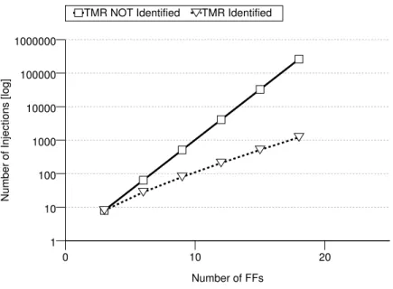
to 2nf(1+n
f), withnf the number of driving FFs for each logic cone. This results in a
considerable analysis speed-up:Fig. 3shows the trend for the number of injections needed asnf increases.
The methodology here presented relies on some assumptions: the whole circuit is driven by only one clock and there are no combinatorial loops. Furthermore, it is assumed that there are no signal conflicts inside the netlist (i.e., two-valued logic) and that there are no timing violations. Finally, we assume that all FFs have one data input and one clock source.
Mathematical model
0 10 20
Number of FFs 1
10 100 1000 10000 100000 1000000
Number of Injections [log]
TMR NOT Identified TMR Identified
Figure 3 Trend for the number of checks needed per for a logic cone with as the number of driving FFs increases.
as outlined in the following. We assume without loss of generality that every gate has just one output. Gates that haven̸=1 outputs are converted intonnodes having the same inputs, each representing one output. Taking this into account the netlist can be easily converted into a directed graph structure
Definition 1Acircuit graph Gis defined as a tuple{V,E,S,F}, where:
• Vis a set of nodes (representing logic gates)
• E⊆V×V×N0is a set of edges (representing interconnection wires)
• S⊆V× {0,1}is a set of values (representing the node values)
• F⊆V×T is the set of logic functions associated to each node, whereT is the set of computable boolean functions
Every nodev∈Vhas 1 outgoing edge andnum inputs(v)⊆N0inputs. The set of valid
input indices for a nodev∈Vis given by
Nv= {1,...,num inputs(v)}.
An edgee=(x,y,i)∈Ewithx,y∈Vandi∈Nyrepresents a connection from nodexto the
inputiof nodey.
Assuming that the input circuit is free of driving conflicts, the circuit graph fullfills the property:
∀v,w,x∈V,∀i∈Nv: v̸=w∧(w,x,i)∈EH⇒(v,x,i)̸∈E
property:
∀x∈V,∀i∈Nx,∃w∈V:(w,x,i)∈E. (1)
To describe the algorithm, we need to define predicates that represent node properties.
Definition 2The set ofdirect predecessorsof nodex, i.e., the set of nodes with a direct connection from their output to one ofxinputs is defined as:
pre(x)= {w| ∃i∈Nx:(w,x,i)∈E}.
Definition 3Let us define the predicateis f f for a given nodex∈V, which determines ifx
represents a FF:
is f f(x)=
true ifx∈V is a FF or in-/output node
false else
For the sake of simplicity, top-level in-/outputs are considered as FFs with no inputs. The set of nodes that represent FFs is:
VFF= {x| ∀x∈V,is f f(x)}.
Definition 4We define the set of nodes which are directly and indirectly connected to the inputs of a given nodex∈V as thesmallestsetpre f fs(x)for which the following properties hold∀w∈pre(x):
is f f(w)H⇒w∈pre f fs(x)
¬is f f(w)∧v∈pre f fs(w)H⇒v∈pre f fs(x).
Having assumed that each FFs has one input, we can define the driving node for a given FF as
Definition 5Adriverfor FFx∈VFFis defined as:
driver(x)= {y|(y,x,1)∈E}.
Finally, we need the operators to compute the values associated to each node:
Definition 6The value of a nodex∈Vis given by theevaloperator, defined as:
eval(x)=
evalFF(x) if x∈VFF
evalL(x) else
whereevalFFreturns the value stored in FFx:
andevalLcomputes the value of logic (i.e., non FF) nodes, which depends on the node
input values:
evalL(x)= {f(eval(y1),...,eval(yn))|(x,f)∈F,yi∈pre(x)}
We also define theconfigurationof a set of FFs{x1,x2,..xn} ∈VFFas
config(x1,...,xn)=(eval(x1),...,eval(xn)).
A configurationconfig(x1,...,xn)is defined asvalidwhen two FFs driven by the same logic
value share the same value for all configurations:
∀x1,...,xn∈VFF,∀i∈Nxi,∀j∈Nxj :driver(xi)≡driver(xj)H⇒eval(xi)=eval(xj)
with≡being defined as functionally identical (see Definition 7).
The proposed methodology is composed of 3 steps:
1. Triplet identification: determine all the FF triplets present in each logic cone
2. TMR structure analysis: perform an exhaustive fault injection campaign on all valid configurations
3. Clock and reset tree verification: assure that no FF triplet has common clock or set/reset lines
These steps are detailed in the following.
Triplet identification
To determine a useful set of valid configurations for a logic cone (here represented by a subgraph), it is necessary to identify which FFs are triplicated, as all the FFs belonging to a triplet have to share the same value. However, the gate naming scheme is usually insufficient. A base assumption for triplet identification is that all triplicated FFs are driven by the same source. An algorithm based on this fact is able to find most triplets, but this simple mechanism is not always sufficient for more complex netlists.
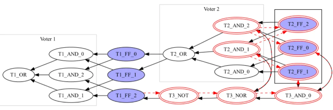
During synthesis, netlists are often optimized in a way that voids this property.Figure 4 shows an example: Voter 2 was partially duplicated using other logic elements, with T2 OR and T3 NOT delivering the same values for all configurations of T2 FF *, thus leaving T1 FF 2 with a different set of inputs with respect to the other members of the triplet. The synthesizer introduces this redundancy for delay optimization, place and route constraints, etc. Therefore, we assume that two FFs belong to one triplet if they are both driven by
functionally identicalnodes.
Definition 7Two nodesx1andx2are functionally identical (x1≡x2) ifpre f fs(x1)= pre f fs(x2)andeval(x1)=eval(x2)for all possible configurations ofpre f fs(·).
Voter 1
Voter 2
T1_OR
T1_AND_0
T1_AND_1 T1_AND_2
T1_FF_0
T1_FF_1
T1_FF_2 T3_NOT
T2_FF_0
T2_AND_0 T2_AND_2
T3_AND_0 T2_FF_1 T2_AND_1
T2_FF_2
T2_OR
T3_NOR
Figure 4 A sample graph with FF triplets and voters after optimization.
simplicity we implemented a simple checker that exhaustively compares all possible input configurations for the two nodes. Checking the equivalence between two nodes might be impractical, as the problem grows exponentially (roughly 2pre f fs(x)). However, wrong
triplet identification affects the verification of TMR protection only with the reporting of
false positives, i.e., reporting a faulty triplicated structure when none exists. Therefore, we propose a heuristic algorithm in three steps.1Let us consider the example ofFig. 4, where
1It is worth noting that other algorithms
for functional equivalence checking can be used here.
Algorithm 1 is applied toT1 FF 2 andT1 FF 1 (xandyin the algorithm, respectively). Two sub-algorithms are needed:
Definition 8mark graph(x)traverses the graph starting at nodexand marks all visited nodes, stopping at FFs. Its behavior is formalized in Algorithm 8.
Definition 9find marked(y,x)traverses the graph depth-first starting fromyuntil a FF is encountered and returns all the nodes that were found as marked byx. Its behaviour is formalized by Algorithm 10.
The first step checks the sets of driving FFs for equality (lines 1–3) before starting fromx
(Fig. 4,T1 FF 2) and traversing the graph depth first, marking all visited nodes (shown as a second circle inFig. 4), until a FF is visited and marked (line 4).
In a second step the algorithm starts again fromy(Fig. 4,T1 FF 1) and traverses the graph until reaching a marked node. If an unmarked FF is traversed, this shows thatxand
yare not functionally identical2in the same clock cycle, and the algorithm aborts. After
2Assuming no FFs were duplicated during
optimization.
terminating successfully, the algorithm returns the set of marked nodes (Alg. 1, line 5). For the example inFig. 4this would beT2 AND 1,T2 AND 2,T2 FF 2.
The third step verifies that all configurations for this set have the same values forxand
y. This is done by assigning all possible configurations to this set (Alg. 1, lines 7–10) and evaluating the subgraph forx,yto compare the results (line 11). Checking all possible configurations, as opposed to only valid ones, might result in functionally identical nodes not being recognized. Instead of drawing a sharp yes/no conclusion, the number of matching configurations is compared for all possible triplet allocations, and the best one is used to assign the FFs. In other words, the nodesxiandxjbelong to the same triplet for
function :functionally identical(x,y)
input : nodesx,y∈V
output : number of matching configurations∈N0
1 ifpre f fs(x)̸=pre f fs(y)then
2 return0;
3 end
4 mark graph(x);
5 (v1,...,vk)←find marked(y, x);
6 count←0;
7 foreachc∈config(v1,...,vk)do
8 fori←1tokdo 9 value(vi)←ci;
10 end
11 ifeval(x)=eval(y)then 12 count←count+1;
13 end
14 end
15 returncount;
Algorithm 1:functionally identical(x,y)
input : a nodex∈V
input : a nodemarker∈V
1 last visit(x)←marker;
2 ifis f f(x)then
3 return;
4 else
5 foreachchild∈pre(x)do
6 mark graph(child, marker);
7 end
8 end
Algorithm 2:mark graph()
input : a nodex∈V
input : a nodemarker∈V
output : a set of nodes(r1,...,rn),ri∈V
1 iflast visit(x)̸=markerthen
2 return∅;
3 else
4 result set←(x);
5 foreachchild∈pre(x)do
6 rek←find marked(child, marker);
7 result set←result set∪rek;
8 end
9 returnresult set;
10 end
Algorithm 3:find marked()
TMR structure analysis
Before starting the analysis, we optimize our description by removing non-relevant elements, as one-to-one buffer gates. As such buffers do not manipulate the logic value of a signal, it is easy to see that the logic functions are not changed when they are removed.
If the TMR implementation were working correctly, a single bit-flip in one FF should not cause another FF to change its value. If a faulty triplicated FF/voter pair exists, there is at least one FF whose value can be changed by a single bit-flip in another FF. This is true only if the configuration before the bit-flip injection was a valid configuration. The algorithm tries to find such FFs, and if none are found, TMR is correctly implemented.
The main idea of the test algorithm is that complexity can be reduced by checking only small submodules instead of the whole system. In order to do this, we observe that a bit-flip in one FF can only distribute to the next FF during the current clock cycle. It is then possible to determine the set of all FFs which could potentially influence a given FFx∈VFF,
i.e.,pre f fs(x), i.e., the FFs drivingx’s logic cone.
The algorithm takes each FFxi and determines the set of FFs that driving its logic
cone, and tests every possible bit flip for every possible valid configuration. If any of these bit flips is able to changexistored value, then the algorithm detected a fault in the
TMR implementation. More formally, Algorithm 4 describes this behavior in pseudocode (whereabortinterrupts execution and shows a message to the user). As the analysis
function :analyze(x)
input : a nodex∈V
1 (y1,...,yk)←pre f fs(x);
2 foreachvalid c∈config(y1,...,yk)do
3 fori←1tokdo 4 value(yi)←ci;
5 end
6 init value←evalFF(x);
7 foreach1-bit mutation c′of cdo
8 fori←1tokdo
9 value(yi)←c′i;
10 end
11 mut value←eval(x);
12 ifmut value̸=init valuethen 13 abort(FF x sensitive to SEUs);
14 end
15 end
16 end
Algorithm 4:analyze(x)
has to be performed for allx∈VFF, analysis times might be excessively long. To reduce
runtime, this algorithm has to be extended to handle large sets of driving FFs(y1,...,yk). If
the number of elementst= |pre f fs(x)|in such a set exceeds a given threshold, the graph will be split into smaller subgraphs until the threshold is reached, as outlined in ‘Splitting algorithm’.
Splitting algorithm
there are a few FFs that are driven by a large number of FFs (for some designs 500 or more). Those subgraphs cannot be analyzed directly as they require 2nconfigurations to be evaluated, and heuristics have to be devised.
A naive approach would use “divide et impera,” splitting every node where
|pre f fs(yi)|>threshold, starting from the FF to be analyzed. It is worth noting that the
count from Algorithm 15 is not what is used here as a threshold. Here we consider only the number of driving flip-flops, and not the number of matching configurations between two logic cones. This approach works for most FFs but fails if the synthesizer merged a voter with other logic during optimization. As an example, a 3-OR gate of a voter might be merged with a following OR gate into a 4-OR gate. Splitting could break the voter and result in a false positive alert.
function :split analyze(x)
input : a nodex∈V
1 split required←false;
2 foreachchild∈pre(x)do
3 if|pre f fs(child)|>THRESHOLDthen 4 replace input(x, child, dummy); 5 split analyze(child);
6 split required←true;
7 end
8 end
9 ifsplit requiredthen
10 (d1,...,dk)←get dummynodes(x);
11 foreachc∈config(d1,...,dk)do
12 fori←1tokdo
13 value(di)←ci;
14 end
15 analyze(x);
16 end
17 else
18 analyze(x); 19 end
Algorithm 5:split analyze(x)
Letchildibe the nodes connected to the inputs of nodex. To avoid breaking voting logic,
instead of splitting using the threshold only, the originating node is kept and the subgraphs for the nodeschildiwith|pre f fs(childi)|>thresholdare replaced by dummy input nodes
(Alg. 5, lines 3–7). Every Nodechildiis tested recursively according to Algorithm 4 with the
divide et impera approach.
Afterwards, all possible bit configurations are assigned to the dummy inputs connected tox(lines 12–14). Analyzingxfor such configurations ensures thatxis tested for all possible substates previously generated by the removed nodeschildi.
It is worth noting that this heuristic relies on the fact that synthesizers tend to keep the voting logic close to the originating FFs, and therefore splitting subgraphs with a large number of inputsusuallydoes not result in voters to be broken.
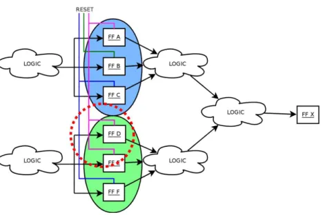
Figure 5 A shared reset line in a TMR triplet might cause issues in case of transients as two FFs might
be affected simultaneously.
algorithm reports a SEU-sensitive FF, testing with a higher threshold value or manual inspection can identify if it represents a false positive.
Clock and reset tree verification
Verifying that the voters are correctly performing their task is not sufficient to guarantee that TMR structures are working. One also needs to show that transient errors on clock and reset lines are not affecting more than one FF at a time.Figure 5shows how a shared reset line might result in SEU-like behavior, as a transient on the line affects more than one FF. This could happen if the FFs shared a common asynchronous reset or clock line: in this case, a bit flip might zero the entire triplet, or force the FFs to sample the wrong value. To guarantee that TMR structures are functioning, it is then necessary to rule out this possibility.
Using the detected triplets, it is possible to verify that FFs belonging to the same triplet do not share the same clock and reset lines. This is a simple structural analysis that does not require an heuristic to be performed.
Algorithm complexity analysis
Givenm= |V|andn= |VFF|, being the total number of gates and FFs, respectively, a naive
exhaustive search would result in 2npossible FF configurations to test, requiringO(m2n)
node evaluations.
Determining a subgraph to be analyzed for every nodex∈VFF, givesnsubgraphs
to verify. Using the properties presented in ‘TMR structure analysis’, the algorithm has to checkpx= |pre f fs(x)|FFs, with typical designs showing that in generalpx≪n. As
described in ‘TMR structure analysis’, the algorithm limitspxto a given thresholdtby
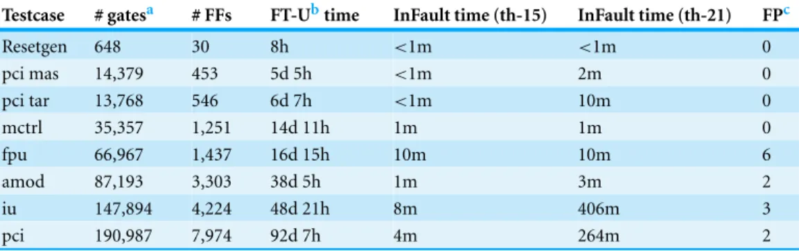
Table 1 Runtime comparison between FT-Unshades and InFault with thresholds 15 and 21.Times in minutes (m), hours (h), and days (d).
Testcase # gatesa # FFs FT-Ubtime InFault time (th-15) InFault time (th-21) FPc
Resetgen 648 30 8h <1m <1m 0
pci mas 14,379 453 5d 5h <1m 2m 0
pci tar 13,768 546 6d 7h <1m 10m 0
mctrl 35,357 1,251 14d 11h 1m 1m 0
fpu 66,967 1,437 16d 15h 10m 10m 6
amod 87,193 3,303 38d 5h 1m 3m 2
iu 147,894 4,224 48d 21h 8m 406m 3
pci 190,987 7,974 92d 7h 4m 264m 2
Notes.
aGatecount after mapping library to standard logic cells.
bnot exhaustive.
cFalse positives, same results for both thresholds.
configurations). As we are testing one bit-flip at a time, we need to performtinjections on every valid configuration. Obviously, the number of subgraphs obtained after splitting and their sizes cannot exceed the total number of gatesm, resulting in less thann·2t·t·m
subgraph evaluations. Overall, the algorithm performsO(nm2)node evaluations, showing polynomial behavior and outperforming other exponential verification methods.
EXPERIMENTAL RESULTS
The algorithm presented in ‘TMR structure analysis’ was implemented as a C++ program called InFault. The graph is obtained in two steps: first a given Verilog netlist is converted into an intermediate file format, which is then read and analyzed by InFault. This separation makes the parser independent from the main program, allowing easy development of parsers for different input files.
The graph itself was implemented in a custom structure, using pointers whenever possible and STL (Silicon Graphics, 2000) maps, vectors, and sort algorithms to maximize speed. In order to be ASIC library independent, the parser is able to read library cell definitions and design netlists, and to map all custom ASIC cells to standard gates (AND, OR, . . . ). If the ASIC library makes use of non-standard cells, the parser and InFault can be easily enhanced. The tool requires no user input during runtime, and shows status information like the overall progress, which gate is being processed, etc.
0 10 20 30 40 50 60 70
3 6 9 12 15 18 21 24
# of false positives
threshold false positives
3 6 9 12 15 18 21 24 0 2 4 6 8 10 12 14 16
runtime (h)
threshold runtime
Figure 6 Runtime and false positive count with increasing threshold.
was calculated based on measurements on smaller tests, using a testbench with 200,000 clock cycles and injecting in every possible FF, assuming a faster-than-real 5 ms runtime for each test. These testbenches come directly from Gaisler Research, and are made with high code-coverage in mind. Therefore, they were considered as a good choice to stimulate every part of the processor. It is worth noting that this short testbench duration cannot cover all possible internal substates therefore resulting in a non-exhaustive test. A testbench that covers all internal substates is hard or even impossible to find and the simulation time would be so high to render the analysis impractical.
Comparing InFault to an exhaustive approach, for example for the pci submodule, we have that this module is verified in less than 7974·2153 ·15·1909872≈1.3·1017node
evaluations (thresholdt=15). A naive approach would require 190987·27974≈4.9·102405 evaluations, showing that InFault provides orders of magnitude of speedup.
As the actual runtime of InFault depends on the choice of the threshold presented in ‘Splitting algorithm,’ we tested several threshold values to determine the speed of the algorithm. In general, smaller thresholds result in shorter runtimes with the drawback of more false positive alerts because of voters that have been broken during subgraph splitting. False positives have to be analyzed by manual graph inspection, or with other means.Figure 6shows how overall runtime and number of false positives vary with increasing threshold, for all nine netlists of the LEON2-FT processor, with a total 19218 FFs and 570959 gates.
The sum of false positives for all nine given designs goes from 63 down to 12. The overall runtime goes from 19 min up to 13 h. For a suggested threshold of 15, the runtime is around 25 min. Please note that the runtime strongly correlates to the internal structure of the design, especially the subgraph sizes, and therefore it is subject to fluctuations among the designs.
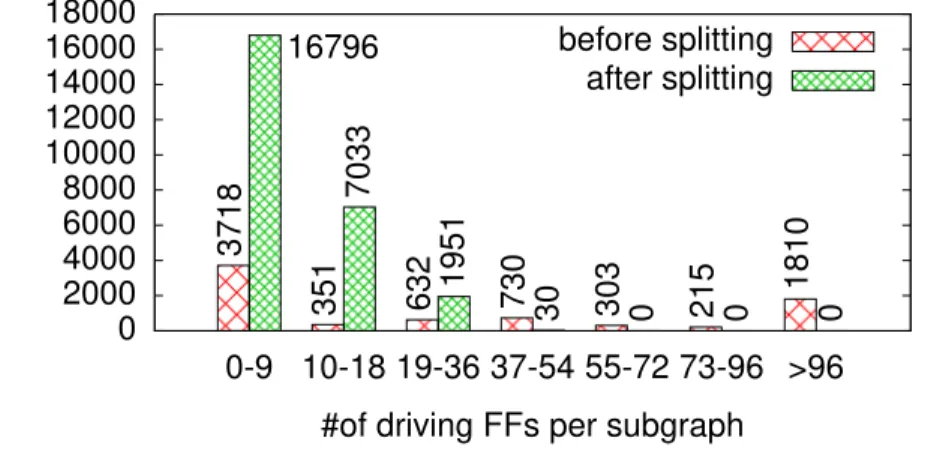
0 2000 4000 6000 8000 10000 12000 14000 16000 18000
0-9 10-18 19-36 37-54 55-72 73-96 >96
count
#of driving FFs per subgraph
16796 before splitting
after splitting
3718
351
7033
632 1951 730 30 303 0 215 0 1810 0
Figure 7 Size classification of subgraphs before and after splitting.
threshold=15).Figure 7shows the results of this test. Before splitting, there are 1,810 subgraphs that consist of>96 driving gates. Assuming correct triplication this would result in more than 232valid configurations to be checked for each of those nodes, making the splitting heuristic an essential component of our approach. In fact, after splitting the situation is completely different: even though the splitting results in many more subgraphs to be checked, the subgraph sizes are much smaller. There are no subgraphs with more than 54 driving gates, giving no more than 218valid configurations.
It is worth noting that the results depend on the complexity of the circuit, since the splitting algorithm effectiveness varies by the number of driving FFs. InFault might not have the same performance with other processors with very complex multi-layer logic.
To show its fault detecting capabilities, InFault was verified on a netlist (moduleiuin Table 1) with broken voters. The netlist used for this test consists of 1,408 triplets (4224 FFs). For the test run 898 triplets were automatically selected, and their voters manipulated by changing the voter function from
f(x1,x2,x3)=(x1∧x2)∨(x2∧x3)∨(x3∧x1)
to
f(x1,x2,x3)=x1∨x2∨x3.
tests showed no additional problems due to the TMR implementation, so that we can reasonably assume that the 351 flip-flops were the cause of the initial testing issues.
CONCLUSIONS & FUTURE WORK
In this work we presented an algorithm to verify TMR implementation for given netlists. Performing exhaustive verification without the need of a testbench, this approach does not suffer from the quality and coverage of the given testbench as in other solutions. First results show that exhaustive TMR verification of production-ready netlists can be carried out within few hours. To the best of the authors’ knowledge, no other approach provides this kind of performance.
Future work includes replacing the actual simulation/injection step with the identifica-tion of triplets followed by formal verificaidentifica-tion of the correct propagaidentifica-tion of flip-flop values through the voting logic.
ACKNOWLEDGEMENTS
The author would like to thank Simon Schulz and David Merodio-Codinachs for the help provided in the development of InFault.
ADDITIONAL INFORMATION AND DECLARATIONS
Funding
The author received no funding for this work.
Competing Interests
The author declares there are no competing interests.
Author Contributions
• Giovanni Beltrame conceived and designed the experiments, performed the experi-ments, analyzed the data, contributed reagents/materials/analysis tools, wrote the paper, prepared figures and/or tables, performed the computation work, reviewed drafts of the paper.
Data Availability
The following information was supplied regarding the availability of data: http://github.com/mistlab/infault.
REFERENCES
Aguirre M, Tombs JN, Baena-Lecuyer V, Mu˜noz F, Torralba A, Fern´andez-Le ´on A, Tortosa-L ´opez F. 2005.FT-UNSHADES: a new system for seu injection, analysis and diagnostics over post synthesis netlist. In: MAPLD’2005, Nasa Military and Aerospace Programmable Logic Devices.Available athttp://klabs.org/mapld05/abstracts/1014 aguirre a. html.
Twenty-Eighth Annual International Symposium on, vol., no., 23–25 June 1998. Piscataway: IEEE Computer Society, 168DOI 10.1109/FTCS.1998.689467.
Carmichael C. 2006.XAPP197: Triple Module Redundancy design techniques for Virtex FPGAs. San Jose: Xilinx Inc.Available athttp://www.xilinx.com/support/documentation/application notes/ xapp216.pdf.
Gaisler J. 2003.The LEON2 IEEE-1754 (SPARC V8) processor.Available athttp://www.gaisler.com. Goswami KK, Iyer RK, Young L. 1997.Depend: a simulation-based environment for system level
dependability analysis.IEEE Transactions on Computers46(1):60–74DOI 10.1109/12.559803. Habinc S. 2002.Functional Triple Modular Redundancy. Technical report. G¨oteborg: Gaisler
Research.Available athttp://www.gaisler.com/doc/fpga 003 01-0-2.pdf.
Kanawati G, Abraham J. 1995.Ferrari: a flexible software-based fault and error injection system.
IEEE Transactions on Computers44:248–260DOI 10.1109/12.364536.
Maestro JA. 2006.SST 2.0: user manual. Universidad Antonio de Nebrija.Available athttp://www. nebrija.es/∼jmaestro/esa/docs/SST-UserManual2-0.pdf.
Seshia SA, Li W, Mitra S. 2007.Verification-guided soft error resilience. In:Proceedings of the de-sign automation and test in Europe (DATE). Piscataway: IEEEDOI 10.1109/DATE.2007.364501. Silicon Graphics. 2000.Standard template library, SGI [Online]. Milpitas: Silicon Graphics.
Available athttp://www.sgi. com/tech/stl.