Abstract—One among several equally important subsystems of a standalone photovoltaic (PV) system is the circuit for maximum power point tracking (MPPT). There are several algorithms that may be used for it. In this paper we choose such an algorithm based on the maximum simplicity criteria. Then we make some small modifications to it in order to make it more robust. We synthesize a circuit built out of elements from the list of elements recognized by SPICE. The inputs are the voltage and the current at the PV panel to DC-DC converter interface. Its task is to generate a pulse width modulated pulse train whose duty ratio is defined to keep the input impedance of the DC-DC converter at the optimal value.
Index Terms—Modeling; Simulation; PV systems; MPPT algorithm.
Original Research Paper DOI: 10.7251/ELS1418011A
I. INTRODUCTION
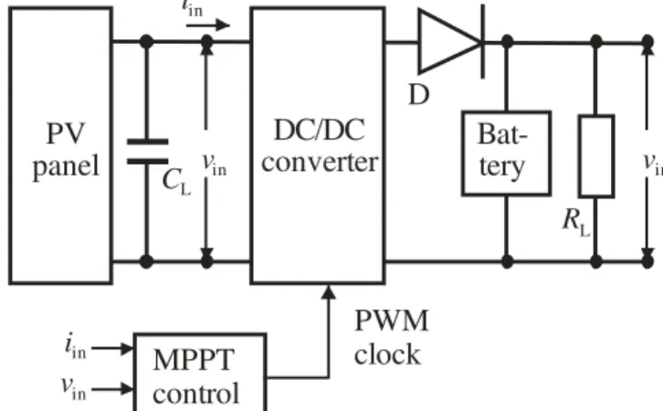
TYPICAL standalone PV system is depicted in Fig. 1. As seen from the figure, it contains the following main subsystems: the PV panel, the line capacitor CL, the DC to DC converter, the maximum power point tracking (MPPT) subsystem, the battery, and the load which is here represented as a resistor RL.
Each part of the system may be realized in different versions. For example there are several circuit architectures for the DC to DC converter; there are different technologies implemented for production of the batteries and, most frequently, the load is a specific electronic system, e.g. metrological measurement station, working remotely.
To design the complete system one has to have circuit models of all subsystems and that is not the case. Namely, to our knowledge there are no published circuit simulations of the whole system. The published simulations are most frequently behavioural using Matlab-Simulink [1,2] which is successful
Manuscript received 13 April 2014. Accepted for publication 30 May 2014.
This research was partly funded by The Ministry of Education and Science of Republic of Serbia under contract No. TR32004.
Miona Andrejević Stošović and Marko Dimitrijević are with the University of Niš, Faculty of Electronic Engineering, 14 Aleksandra Medvedeva, 18000 Niš, Serbia (e-mail: [email protected], [email protected]).
Duško Lukač is with the Rheinische Fachhochschule Köln, Germany (e-mail: [email protected]).
Vančo Litovski is with NiCAT - Niš Cluster of Advanced Technologies,
18000 Niš, Serbia (e-mail: [email protected]).
when looking at the system level but makes it difficult to implement models of real components due to lack of proper libraries.
Circuit simulation with SPICE [3] and SPICE-like software enables easier data transfer to a PCB layout design tool so making the design process continuous, reducing the format translation activities, and minimizing the risk of error during manipulation of data.
i
inv
ini
inv
inMPPT
control
DC/DC
converter
C
LD
Bat-tery
R
LPWM
clock
v
inPV
panel
Fig. 1. System level schematic of a standalone PV system.
To our knowledge most of the parts of the PV system de-picted in Fig. 1. are already modeled and simulated in SPICE e.g. [4,5,6]. However, there are no published results reporting SPICE modeling and simulation of the MPPT circuit. By cre-ation of such a model, we expect, one will be capable to simu-late and design the whole standalone system, hence the importance of this work.
The paper is organized as follows. First we will describe the basic properties of the PV panel from the sensitivity to illumination and temperature point of view in order to establish the feeling about the reason why the maximum power point is migrating during the operation of the PV system. Then, we will describe the most frequently used algorithm for MPPT named Perturb and Observe (P&O), as described in [7,8,9]. A minor improvement of the way how the algorithm is expressed will be introduced leading to a Modified Perturb and Observe (MP&O) algorithm. Finally, the SPICE model of the MPPT and simulation results verifying the model reported will be introduced.
II. MPPT ALGORITHM
Fig. 2. depicts the dependence of the photovoltaic power produced by a PV panel on the voltage on it with the illumination as a parameter [7]. As it may be seen the MPP
SPICE Modeling and Simulation
of a MPPT Algorithm
Miona Andrejević Stošović, Marko Dimitrijević, Duško Lukač,
and Vančo Litovski
A
migrates slightly due to the change of the output resistance of the panel [10].
As a counterpart to this dependence the migration of the MPP with temperature is shown in Fig. 3. [7]. Due to these reasons every PV system is equipped with a specific circuitry which controls the duty cycle of the pulse train controlling the switches within the converter (inverter). These changes lead to changes of the input resistance of the converter and if the control is properly tailored the PV panel will be kept in a position to deliver maximum power to the converter.
Panel voltage (V)
2 4 6 8
0 10 12 14 16 18 20 22
100 Illumination
1000 700 500 300 W/m
W/m W/m W/m
2 2 2 2
Ph
o
to
v
o
lt
a
ic
p
o
w
er
(W
)
50
MPP
MPP
MPP
MPP
Fig. 2. Photovoltaic power versus panel voltage for different illumination intensities.
Panel voltage (V)
0.0 5.0 10.0 15.0 20.0 25.0
70.0
60.0
50.0
40.0
30.0
20.0
10.0
00.0
P
h
o
to
v
o
lt
ai
c p
o
w
e
r
(W
)
T=0 Co
T=25 Co
T=50 Co
MPP
MPP MPP
Fig. 3. Photovoltaic power versus cell voltage for different temperatures.
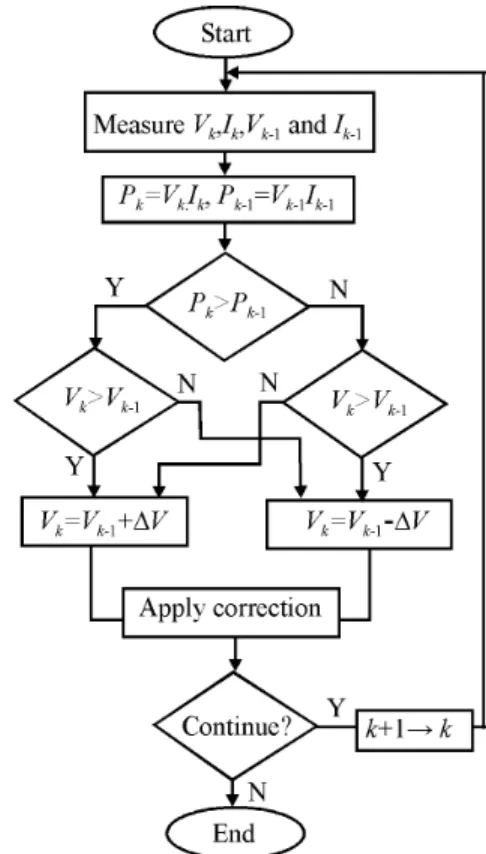
As already mentioned in Introduction there are several techniques and algorithms enabling implementation of the idea of tracking the MPP. Among them the most popular is the so called Perturb and Observe (P&O) which is depicted in Fig. 4. [8,9]. One may see from the figure that as a result a fixed increment (positive or negative) of the PV panel voltage is produced after each sampling period (of the voltage and the power of the PV panel). In real circuit this increment is used as information for a pulse width modulated (PWM) oscillator to control its duty ratio.
Fig. 4. The perturb and observe algorithm.
Fig. 5. The modified perturb and observe algorithm.
There are four branches in this algorithm that lead to two signs of the increment. If (Pk-Pk-1>0 and Vk-Vk-1>0) and if
(Pk-Pk-1<0 and Vk-Vk-1<0) the increment is positive. The value of the increment is negative if (Pk-Pk-1<0 and Vk-Vk-1>0) and
if (Pk-Pk-1>0 and Vk-Vk-1<0). By careful inspection one may
conclude that the sign of the increment is associated to the sign of Qk=(Pk-Pk-1)(Vk-Vk-1). If Qk>0 the increment is positive
and if Qk<0 the increment is negative. This way of expression
simplifies the whole diagram and probably the electronic circuitry implementing the algorithm.
Note that the algorithm is generating an increment no matter how large the differences (Pk-Pk-1) and (Vk-Vk-1) are, which,
generally speaking, for small differences may lead to a duty cycle becoming much larger than necessary which may even be counterproductive i.e. it may leat tolead the quiescent point
out of MPP region by "overshooting" it.
Having all that in mind we propose a modification of the algorithm as depicted in Fig. 5. In this algorithm, after calculation of Qk one first makes a comparison with a
threshold value Qref. If Qk is not larger than Qref there is no need for perturbation i.e. for a change of the duty cycle. If it is larger, only the sign of Qk is used to create the sign of the
voltage increment.
Note that the implementation of this idea may lead to an additional benefit. Namely, by proper choice of Qref and V,
larger increments (V) may be implemented since oversho-oting is disabled. In other words one may expect faster recovery of the MPPT.
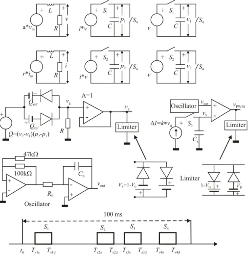
Fig. 6. The SPICE schematic modelling the MPPT control circuit.
III. SPICE MODEL OF THE MPPT ALGORITHM AND SIMULATION RESULTS
The SPICE implementation of the algorithm in Fig. 5. is depicted in Fig. 6. Further we shortly describe its units.
First, since the measured output voltage (v) and current (i) of the PV panel contain components that may be constant, slowly time-varying (due to change of temperature, illumination and the load) and very fast (due to the commutation within the converter), we implement a filtering
function to eliminate the high frequency component. That is done by a L-R low-pass filter as shown at the top left part of the figure.
Next, we sample both the voltage and the power. It is done by a sample and hold circuit that starts at Ts1s and ends at Ts1d.
The sampling circuitry is depicted in the top part of the figure (associated with S1) while the timing diagram is given at the
bottom. After this operation the capacitors in these two circuits memorize the sampled values of p1 and v1.
which is adjustable based on how fast changes of temperature and illuminations are expected. Here the sampling instant (associated with S2) is denoted by Ts2s. So after Ts2d we have
two new samples: p2 and v2.
Having these four quantities we compute Q=(p2-p1)(v2-v1)
which is represented in Fig. 6. as a controlled voltage source. That signal is contrasted to Qref and the result is brought to a
limiter so that vq takes (approximately) values 0, 1V and -1V,
only.
The resulting vq is used to create the voltage increment at
Cx. It is vx=k∙vq∙t/Cx, where t=Ts3d-Ts3s. This increment is
brought to one of the inputs of a comparator. The second input of the comparator is excited by the output (voltage) signal of an oscillator that produces symmetrical alternatively linearly rising and linearly falling signal. The oscillation period is equal to the switching period of the converter so that at the output of the limiter connected to the comparator`s output one gets pulse width modulated signal.
After completion of the sampling at S3, using S4 the sampled
values of v1, v2, p1, and p2, are erased and a new measurement
and control cycle is enabled. Here, to shorten the computer time, a measurement/control period of 100 ms was used. In real world that interval is supposed to be longer.
The following set of parameter values was used to enable the simulation of the circuit in Fig. 6: a=1, r=1Ω, C=1µF, L=1H, R=1kΩ, Qref=0.5V, Rs=10kΩ, Cs=0.9nF, k=10-3,
Cx=14.3mF, Ts1s=5ms, Ts1d=10ms, Ts2s=70ms, Ts2d=75ms,
Ts3s=85ms, Ts3d=90ms, Ts4s=95ms, Ts4d=100ms. No battery was
included in the system.
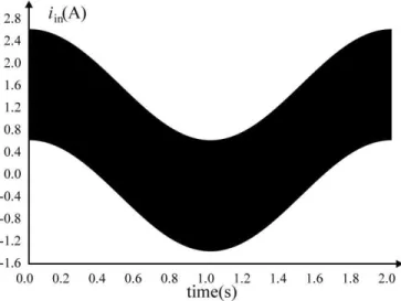
To illustrate the implementation of the algorithm an example will be shown. Instead of getting the signals directly from the PV panel, for verification purposes, we created two signals as follows (Figs. 7 and 8):
v(t)=2+ sin(2π·50000·t)+sin(2π·0.5·t) [V] (1a) i(t)=0.6+sin(2π·50000·t)+sin(2π·0.5·t+/2) [A]. (1b)
Fig. 7. Input voltage signal.
Fig. 8. Input current signal.
These were used as excitation for the circuit in Fig. 6. Fig. 9. depicts the signal Q of Fig. 6. Finally, Fig. 10 illustrates the dependence of the duty cycle at the output of the circuit in Fig. 6. It is clear that it follows the shape of Q. It also implements the new version of the MPPT algorithm presented in Fig. 5.
Fig. 9. The Q=(p2-p1)(v1-v2) product.
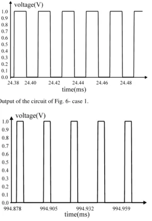
In Figs. 11 and 12 pulses at the circuit output are given for two different time instances. We can see that pulse width dramatically changes in time, which was in fact the goal.
Fig. 11. Output of the circuit of Fig. 6- case 1.
Fig. 12. Output of the circuit of Fig. 6- case 2.
CONCLUSION
An improvement was proposed to the existing MPPT algorithm since a drawback was noticed in it. To verify the new idea SPICE simulation of the whole system containing the PV panel, the line capacitor, the converter, and a resistive load, was performed. A specific contribution of this paper is an original SPICE model of the subsystem performing the MPPT
algorithm. Future implementations of these achievements are expected in the simulation of the system performance under dynamic changes of the load extended with a super- capacitor charging system.
REFERENCES
[1] A. D. Hansen, P. Sorensen, L. H. Hansen, and H. Bindner, “Models for a stand-alone PV system,” Riso, National Laboratories, Roskilde, Denmark, 2000, http://orbit.dtu.dk/fedora/objects/orbit:91233/ datastreams/file_7727175/content.
[2] B. Sree Manju, R. Ramaprabha R., B. L. Mathur, “Design and Modeling of Standalone Solar Photovoltaic Charging System”, Int. J. of Computer Applications, vol. 18, no. 2, pp.41-45, March 2011. [3] L. W. Nagel, D. O. Pederson, SPICE (Simulation Program with
Integrated Circuit Emphasis), University of California, Berkeley, Memorandum ERL-M 382, April 1973.
[4] V. Litovski, M. Savić, Ž. Mrčarica, “Electronic circuit simulation with
ideal switches,” HAIT Journal of Science and Engineering B, pp. 476-495, July 2005.
[5] E. W. Enlow, D. R. Alexander, “Photocurrent modeling of modern
microcircuit pn junctions,” IEEE Trans. on Nuclear Science, vol. 35, no. 6, pp. 1467–1474, Dec 1988.
[6] K. H. Edelmoser, F. A. Himmelstoss, “Bi-directional DC-to-DC
Converter for Solar Battery Backup Applications,” 35th Annual IEEE Power Electronics Specialists Conf., Aachen, Germany, pp. 2070-74, 2004.
[7] V. Salas, E. Olías, A. Barrado, A. Lázaro, “Review of the maximum power point tracking algorithms for stand-alone photovoltaic systems,”
Solar Energy Materials & Solar Cells, no. 90, pp. 1555–78, 2006. [8] T. Esram, and P. L. Chapman, “Comparison of Photovoltaic Array
Maximum Power Point Tracking Techniques,”IEEE Transactions on Energy Conversion, vol. 22, no. 2, pp. 439-449, June 2007.
[9] C. S. Chin, M. K. Tan, P. Neelakantan, B. L. Chua, and K. T. K. Teo,
“Optimization of Partially Shaded PV Array using Fuzzy MPPT”, IEEE Colloquium on Humanities, Science and Engineering Research (CHUSER 2011), Penang, China, pp. 481–486, Dec. 2011.
[10] M. Andrejević Stošović, M. Dimitrijević,D. Lukač, and V. Litovski,
“Quantification of Power Quality Issues at the PV Panel-Converter
Interface,” Proc. of the IX Symp. on Industrial Electronics, INDEL 2012, Banja Luka, B&H, pp. 256-262, Nov. 2012.