The Effect of Dewaxing and Burnout
Temperature in Block Mold Process for
Copper Alloy Casting
S.Z. Mohd Nor#1, R. Ismail#2, S. Ahmad#3, M. I. N. Isa#4
#1
SIRIM Negeri Terengganu, Kawasan Perindustrian Chendering, 21080 Kuala Terengganu, Terengganu, Malaysia
1
#2
Foundry Technology Section, National Centre for Machinery and Tooling Technology, Kawasan Perindustrian Rasa, 44200, Rasa, Hulu Selangor, Selangor, Malaysia
2
#3
Faculty Science and Technology, National University of Malaysia 43600, Bangi, Selangor, Malaysia
3
#4
Advanced Materials Research Group, School of Fundamental Science, University Malaysia Terengganu, 21030, Kuala Terengganu, Terengganu, Malaysia.
4
Abstract
The main objective of this research is to investigate the effect of dewaxing and burnout temperature on the quality of copper alloy casting produced by a low cost block mold that has been developed. In the molding process, two types of silica sand which contains 97.9% silica (SiO2) and 97.2% silica have been used as a
refractory material with POP served as a binder. Several mold formulations contained 15-40% plaster of paris (POP), 60-85% silica sand and 35% water had been developed and each formulation had been tested in the process of copper alloy casting. In the dewaxing process, the temperature of 170oC was found appropriate to be used as an initial mold heating temperature and complete wax burnout was effectively achieved with the temperature of 750oC for 5 hours. The insufficient burnout process has produced a defect casting with carbon residue, appeared as a black stain on the surface of the casting. Meanwhile, rapid initial heating had prevented the wax from flowing out smoothly thus, eroded the surface of the mold cavities. This has resulted in deteriorated cavity surface, hence a rough surface of the casting.
Key words- Block mold, Wax pattern, Dewaxing temperature, Burnout temperature, Copper alloy
I. INTRODUCTION
In the current literature about the casting processes, the application of block mold casting is hardly addressed, although this process has numerous global applications [1]. The block mold process which utilizes investment powder as a molding material has been used in jewelry casting, artworks, surgery implants and dental. Almost all metallic dental implants are produced using this process [2], [3]. This process also has a role in engineering applications, mostly for nonferrous alloys. Due to the high degree of freedom this process is suitable for the production of technical devices and this method is also regularly used in the production of silver or gold casting in the jewelry industry [4], [5]. The solid or block mold had also been used in the study of processing parameters on fluidity and the mechanical properties of investment-cast magnesium alloy [6], [7].
In this process, the wax patterns are removed from the mold by means of melting, hence they do not have mold parting. Due to this step, complex and near net shaped casting geometries which possess undercuts can also be produced. Apart from these advantages, it also exhibits a very low surface roughness compared to sand cast components, thus reduced the machining cost. The difference between shell mold of investment casting and block mold casting processes arises in the mold material used and therefore on the mold. Thus, in comparison to the shell mold process, a great deal of process time and expenditure can be saved during the block mold casting process. [8], [9]. In addition to this, the block mold castings are easier to demold.
Bonilla et al [8] had studied the effect of wax pattern accuracy on the dimension of cast parts and they reported that computer aided modeling can be used to predict the wax pattern contraction. Idris and Sharif [10] had reported that a hollow pattern of rapid prototype of Acrylonitrile Butadiene Styrene (ABS) had better dimensional accuracy. Therefore, in conjunction with rapid prototyping patterns, this casting method enables extremely complex castings variably and flexibly manufactured to their final near net shape [11], [12].
as calcium sulfate hemihydrate is produced by heating gypsum to about 150oC. When the dry plaster powder is mixed with water, it re-forms into gypsum crystals and these crystals created interlocking and hence, bond the refractory grain of the molding material [5]. Mold material composition and mixing process are the main factors that will determine the success of the molding process. Too little water will produce a thick mixture but more than 50% water content will produce a weak mold which could not stand the firing in the furnace. In a similar way, the high content of POP will produce thick slurry and will cause failure in the molding process. Besides formulation, mixing time and slurry flowability are the factors that will determine the success of the process. Over-mixing will make the slurry thicken thus foil the process, meanwhile, insufficient mixing time will result in separation of molding material.
In dewaxing and preheating process, the mold is preheated for several hours to remove the wax patterns and to preheat the mold for pouring process. The molds should not be heated above the decomposition temperature to avoid a reduction in strength. Different decomposition temperatures had been reported by previous researchers, where Jones [14] suggested that the rapid decomposition of gypsum bonded mold occurred between 900 and 1000oC. Meanwhile, Matsuya and Yamane [15] reported that the decomposition had begun at about 900oC and the process had led to the formation of CaSiO3. However, the decomposition of gypsum does not
seem to take place in the range of manufacturers’ recommended burnout temperature that is roughly at 500– 750oC.
The most common cause of defects arising during casting process can be connected to the molding process, which commenced with slurry preparation and ended with the mold burnout process [16]. The incomplete mold filling is another common defect that should be mentioned, which can usually be associated with inadequate mold temperature and the causes of poor mold-filling can be detected relatively easily. Fin or flash in castings can often be related to cracks in the mold. Veining is a typical form of defect that occurs due to fine line cracks in the mold which forms as a vein-like crack. The defect appears as thin and irregular metallic protuberances on the surface of the casting.
In Malaysia there is growing interest in application of block mold process for the production of craft products, engineering parts and household products, but the high price of commercial block mold material (investment) had become a constraint in production cost. Mohd Nor et al [17] had reported that Kuala Abang’s (KA) silica sand had 97.9% silica (SiO2) content and Jambu Bongkok’s (JB) silica sand contained 97.2% silica,
hence highly potential to be developed as mold material for copper alloy casting. Thus, it is anticipated that by developing a suitable block mold formulation using local silica sand, the molding cost can be significantly reduced without compromising the product quality. The main objective of this study is to investigate the effect of dewaxing and burnout temperature of the developed block mold on the copper alloy casting quality.
II.EXPERIMENTALPROCEDURE
A. Mold Formulations
Kuala Abang’s (KA) silica sand and Jambu Bongkok’s (JB) silica sand which have 50-60 grain fineness number (GFN) were used to develop a suitable block mold formulation for copper alloy casting. Plaster of paris (POP) was used as a binder and two types of POP from two different manufacturers were used. Prior to the molding process, raw silica sand was sieved in advance using a sieve shaker. By only selecting the grains with a size of 150-300 µm, several mold formulations using 15-40% POP, 60-85% silica sand and 35% water were developed. The mixture of POP, silica and water are called slurry and to minimize the formation of bubbles, 1% of anti foaming agent was added. Then, following the developed formulations, several molds were made and each of these molds had been tested in the casting process of copper alloy. Table I and II show the sample formulation and its abbreviation used in this study.
TABLE I: Samples Formulations and its Abbreviation Used (KA silica)
Sample KA Silica (%) Eurochemo POP (%) Cast-C POP (%) Water (%)
KA1 85 15 0 35
KA2 80 20 0 35
KA3 75 25 0 35
KA4 70 30 0 35
KA5 65 35 0 35
KA6 60 40 0 35
KA7 85 0 15 35
KA8 80 0 20 35
KA9 75 0 25 35
KA10 70 0 30 35
KA11 65 0 35 35
TABLE II: Samples Formulations and its Abbreviation Used (JB silica)
Sample JB Silica (%)
Eurochemo POP (%)
Cast-C POP (%)
Water (%)
JB1 85 15 0 35 JB2 80 20 0 35 JB3 75 25 0 35 JB4 70 30 0 35 JB5 65 35 0 35 JB6 60 40 0 35
JB7 85 0 15 35
JB8 80 0 20 35
JB9 75 0 25 35
JB10 70 0 30 35 JB11 65 0 35 35 JB12 60 0 40 35
B. Block Mold Process
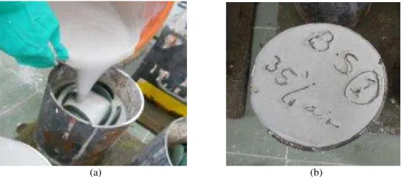
Prior to the molding process, a wax pattern which resembles a saucer with a diameter of 6.5 cm was made by injecting liquid wax into an aluminum die. The pattern was left to solidify and subsequently, it can be removed from the die. A wax injection machine was used and its setting was 78oC wax temperature, 50 kPa injection pressure and 2 seconds injection time. Then the wax pattern was attached to the gating system which consists of pouring cup, sprue, runner and ingate later to be known as wax tree. The schematic diagram of the wax tree is shown in Fig. 1. During the molding process, the wax tree was placed on a wooden plate and encircled with a metal flask. In this study, 6 kg of block mold with the flask dimension of 16.5 cm in diameter and 23.0 cm of height was used. To facilitate slurry mixing and avoid lumpy mixture, POP was added to the water and waited for it to dihydrate before further mixing to obtain a homogenous mixture. Then the silica sand was added and the mixing process was continued until a creamy and thick slurry (mold mixture) with an optimum viscosity was achieved. After that, the slurry was poured into the flask and permitted to set through chemical reaction to form a block mold. The molds should be left undisturbed for at least one hour. An optimum slurry viscosity that is around a diameter of 7.7-9.6 cm (from slump test) is essential to ensure that the wax pattern is able to be fully invested. Within this range of viscosity, the slurry has excellent flowability where the slurry effortlessly flowed and filled the empty spaces between the wax patterns, hence covering all surfaces of wax patterns. The slurry with the diameter of 6.2-7.5 cm (from slump test) had shown good flowability with easy pouring, but sometimes, this formulation required more attention as it needed to be spread out using a wooden stick. Fig. 2 shows the molding process to make a block mold and slurry with excellent flowability poured effortlessly into the metal flask. During the setting process, branched gypsum crystals were formed, hence bonded the refractory grains of the molding material.
Fig. 1. The schematic diagram of wax tree with gating system. Pattern
Ingate
Runner
(a) (b)
Fig. 2. Molding process where, (a) slurry with excellent flowability could be poured easily into the metal flask and (b) harden slurry forming a block mold.
C. Casting Processes.
After six hours, the mold was placed in the furnace for dewaxing and preheating process. At one time, 6 molds can be placed in the oven by standing them on fire bricks with the pouring cup facing downwards. At the initial stage, it was heated at 170oC at a rate of 1.6C/min and was held at this temperature for 3 hours. After that, the temperature was increased to 750oC at a rate of 1.9C/min and held at this temperature for 5 hours. At this stage, burnout process was expected to occur to completely eliminate all the wax residue in the mold. Afterward, the mold was cooled in the furnace to the desired casting temperature. In this study, for the pouring of copper alloy with the composition of 60% Copper and 38% Zinc (Brass), mold temperature was fixed at the temperature of 500oC. Graphite crucible was used in the melting process where the furnace firing can be controlled by a valve in the gas piping. Once the molten metal had reached its pouring temperature, slag was removed and the molds were taken out of the furnace. Then the molten metal of copper alloy was poured at a temperature of 970oC before it was left to cool down and solidified. After it had solidified, the castings had been removed by knocking the molds with a hammer and they were examined carefully to evaluate the quality of castings and to see which defect occurred. In block mold casting, the defects that can be related to molding and dewaxing process are misrun, flash or fin, veining, and sandy surface of the casting. The schematic diagram of the casting process is illustrated in the Fig. 3.
Fig. 3. Casting processes where (a) fabrication of wax pattern tree (b) wax tree with the gating system (c) encircled with metal flask, (d) wax patterns embedded in molding material, (e) dewaxing and burnout process
(f) pouring of molten metal.
c
III. RESULT AND DISCUSSION
A. Dewaxing and Preheating Temperature
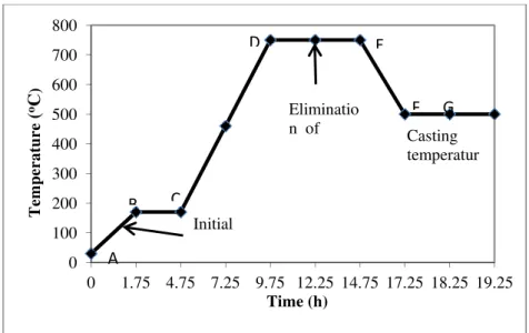
Fig. 4 shows the dewaxing and preheating temperature employed in this study. From point A to B as indicated in Fig. 4, the mold was subjected to the slow heating process from room temperature to 170oC. During these points, water in the mold turned into steam at 100oC and escaped through the pores of the mold. The wax pattern embedded in the mold material started to melt at the temperature of 75oC and from 75oC to 170oC, most of the wax melted and flowed out through the runner and mold opening (pouring cup). The steam from the water in the moist mold helped to push wax off the walls of the cavities in the mold.
From the point C to D, as the furnace temperature increased to 750oC, the wax which did not flow out turned to carbon, appeared as a black powder at 538oC. To ensure that the dewaxing oven is rich with oxygen the furnace must be ventilated. At 700-750oC, the carbon combined with oxygen from the air formed carbon monoxide (CO) and carbon dioxide (CO2) gases hence eliminated any traces of carbon in the mold. The gases
escaped through the runner and pouring cup and also through the pores of the mold. Then the mold was further heated at 750oC (which is known as burnout temperature) to eradicate any traces of carbon as depicted by point D to E. Carbon must then be eliminated from the mold at this high temperature for approximately 5 hours. After 5 hours the burnout process had completed and it created clean mold cavities without a trace of carbon. However, there was still a wax residue in the form of ash (microscopic trace residue) and usually, its value should not be more than 0.015% by weight. Waxes with a high ash content can cause porosity and inclusions in the casting. Finally, the mold was allowed to cool down to the casting temperature depending on the alloy being used. This process could take take more than 2 hours and the ramp of point E to H shows the gradual drop of the mold temperature to the desired mold temperature for pouring process of copper alloy that is 500oC.
Fig. 4. Dewaxing and preheating temperature setting in the furnace.
B. Mold Condition after Dewaxing and Preheating.
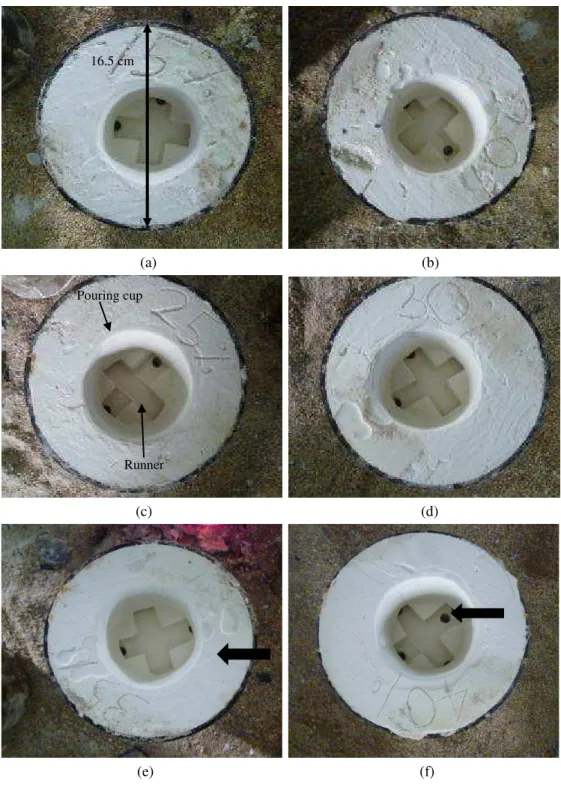
After dewaxing and preheating processes, the molds had been taken from the furnace and transferred to the pouring area at room temperature. Fig. 5 (a)-(f) show the block mold (formulation of JB7- JB12) with 60-85% silica and 15-40% POP content after dewaxing and preheating process at 500oC. As clearly shown in the Fig. 5, the suitable dewaxing and preheating temperature has produced clean molds with fully developed cavities. Outer cavity known as pouring cup and the molten metal will enter the inner cavity through a runner. The pouring cup is shown as the round shaped cavity in the Fig. 5 (c). If the mold has not been sufficiently heated in the burnout process, traces of grey coating carbonized wax could be observed and from the picture, all the molds depicted chalky white surface indicating that the wax residue had been fully eliminated during the burnout process. It was also found that, the dewaxing and the preheating process did not induce any severe cracks, but very fine cracks (show by arrow) could be observed on the mold surface and the crack was more obvious in the formulation of 35% POP and 40% POP. Calcium sulfate dihydrate or gypsum shrank up to 2% upon heating and varying the percentage of gypsum to the silica has changed the thermal expansion profile of the mold. Formulations with higher gypsum content will have a higher shrinkage percentage, thus higher tendency in causing cracks. It was believed that these cracks grew bigger due to thermal stresses which occurred during the transfer process from the dewaxing and preheating furnace at the temperature of 500oC to the pouring area. Mori [18] had also
0 100 200 300 400 500 600 700 800
0 1.75 4.75 7.25 9.75 12.25 14.75 17.25 18.25 19.25
Temperature ( oC ) Time (h) Eliminatio n of
reported that a large shrinkage was observed in the gypsum bonded mold which had been used in dental casting. However, it has been observed later that these cracks did not cause any molten metal leakage.
A similar observation was attained for KA formulations where fine cracks were also observed on the mold surface of formulation of 35% and 40% POP, but did cause molten metal leakage during the pouring process. The condition was consistent for all formulations tested.
(a) (b)
(c) (d)
(e) (f)
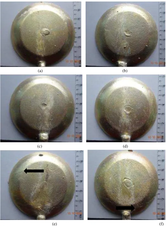
Fig. 5. Developed molds using the formulations of JB7-JB12 where (a) 15% POP (b) 20% POP (c) 25 % POP (d) 30 % POP (e) 35 % POP
(f) 40 % POP after dewaxing and preheating at 500oC. Arrow shows fine crack on the mold surface.
C. Effect of Burnout Temperature on the Mold.
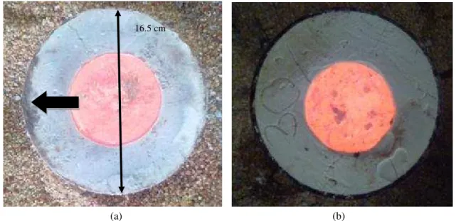
To achieve complete burnout process, the mold should be heated at sufficient temperature in an appropriate time and Fig. 6 depicts the difference following the insufficient and complete burnout process. Fig. 6 (a) depicts the mold of incomplete burnout and Fig. 6 (b) shows the mold after complete burnout. As clearly can be seen in Fig. 6 (a), insufficient burnout process has generated mold with the grey coating on the surface and in the worst case, black carbon stain could be observed (arrow). Meanwhile, the complete burnout process has produced clean white mold, as shown in Fig. 6 (b). Occasionally some stains remained but in general the pouring cup will
Pouring cup
Runner
turn from grey to chalky white [19]. In the pouring process, apart from clean mold, it should be able to withstand the flow and pressure of the metal at high temperature. Fig. 6 also shows the developed molds after pouring process. The pouring of copper alloy molten metal had been done successfully, confirmed that the molds were able to withstand the load during the mold handling and the load due to the casting process. It was also shown that there was no metal leakage for both molds and full-filled of pouring cup also confirmed that there was no severe cracks induced in the mold. Therefore, the insufficient burnout process was only likely to affect the casting quality, but not the mold strength. During the knock out process, the molds were easily broken under the force of the hammer. The low strength of block mold had enabled the casting to be easily removed from the mold [20].
(a) (b)
Fig. 6. Mold after pouring (a) incomplete burnout shows traces of grey coating carbonized and (b) complete burnout produces chalky white mold.
D. Quality of Castings
Misrun defect is the defect where a portion of the casting is missing and the defect can usually be associated with inadequate mold temperature or improper gating system. As-cast surface of copper alloy castings produced by the formulations of JB7-JB12 are depicted in Fig. 7. It can be clearly seen that for all formulations tested, a complete filled casting was obtained without misrun defect, The castings also display no sign of other major defect such as the fin or flash which normally occurs due to severe mold cracks, thus confirmed that the cavities were fully formed without severe cracks. In spite of perfectly formed casting, it was also observed that some of the castings have several tiny nodules on its surface. These nodules were formed when the liquid metal filled a tiny pores in the inner surface of the mold. During the molding process, the entrapment of air bubbles in the mold material had created tiny pores and to get a smoother surface of casting, air bubbles in the mold material should be allowed to escape during the process. In addition, veining defect was also observed on the surface of castings produced by formulation of 35% and 40% POP, but this defect did not appear in the formulation of 15-30% POP. This means that for the formulation of 15-15-30%, the cracks only occurred in the outer layer of the mold. According to Luk and Darvel [20], the mold tended to form cracks during the firing process which can produce casting defects. But in this study, it has been found out that the high POP content also can cause small cracks in the mold. The defect occurs when a liquid metal filled a line-shaped crack in the mold and the defect is shown by the arrow in the Fig. 7 (e) and (f). However, these two defects was not a severe defect which could be easily removed during the finishing process. Ott [16] had also stated that both types of defects were restricted to the surface only and neither mechanical properties, nor microstructure were influenced. It was also found that, the surface roughness (Ra) of the castings was around 1.7-2.6 µm and it was not affected by the POP content. Therefore, it can be said that, although all developed formulations could be used in the casting process, formulations of 15-30% POP was more appropriate for copper alloy casting. The same result was also observed for KA silica. The similar results were found by Ott & Raub [3] which reported that, a molding material with 25 to 30 % gypsum and 70 to 75% silica can be used to cast nonferrous alloys such as gold and silver alloys as well as nickel-chrome alloys.
(a) (b)
(c) (d)
(e) (f)
Fig. 7. Castings produced using the formulation of JB7-JB12 where (a) 15% POP, (b) 20% POP, (c) 25 % POP (d) 30 % POP, (e) 35 % POP and (f) 40 % POP.
Ott [16] had suggested that the mold deterioration can also be caused by the violent boiling of surplus water in mold material and these defects were reproduced on the casting. During the mixing process, partially dihydrated calcium sulfate combined with water and formed a network of (hydrated) gypsum crystals which bound the refractory silica grains together. In the heating process, gypsum lost a part of its water in a temperature range of 190-200°C. The bonding strength can only be maintained if this process occurred slowly [16]. Heating the mold quickly also made the water known as water of hydration turned to steam and the generated pressure could induce cracks. The escaping steam also able to break the thin mold material which acted as dividers between the wax patterns. Therefore, by lowering the temperature to 170oC, the wax had enough time to flow out smoothly, the mold could dry slowly, hence resulted in the smooth surface of the mold cavities.
(a) (b)
Fig. 8. As-cast product with (a) rough sandy surface and (b) improved surface after reducing initial dewaxing temperature.
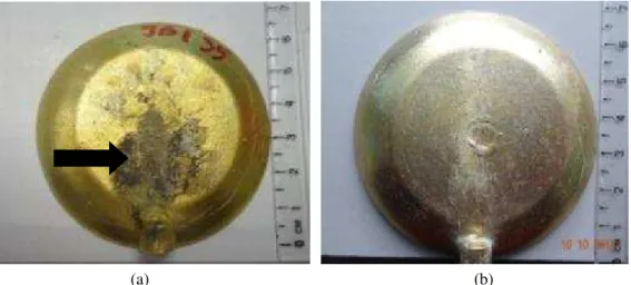
2) Effect of Burnout Temperature: Good airflow in the oven is important to achieve complete burnout process. Lack of oxygen in the oven can promote a reducing atmosphere. At elevated temperatures this atmosphere causes the calcium sulfate within the mold material to decompose releasing sulfur. At an earlier stage of this study, burnout process was done at 750oC for 2 hours. Then it was found that 2 hours was inadequate to burn all the wax residue (carbon) inside the mold cavities. Incomplete burnout had resulted in a cavity contained residual carbon and when the molten metal was cast into the mold, it has stained the metal and discolor the casting. The carbon can be so deeply and firmly bonded to the metal so that it can only be removed by sanding process. The effect of insufficient burnout process is shown in the Fig. 9 (a), where the casting produced has a black stain (shown by arrow) on its surface. The carbon also could react with the metal on entering the mold and created gases. These gases then can be trapped under the skin of the metal and as it solidified it can lead to pin holes defect. Meanwhile, Fig. 9 (b) shows the surface of casting following the complete burnout process which was carried out at 750oC for 5 hours. The casting has a bright surface without stain, thus confirmed that the temperature of 750oC for 5 hours was appropriate.
(a) (b)
Fig. 9. Effect of (a) incomplete burnout and (b) sufficient burnout process on the casting surface E. Cost Reduction for Local Industry
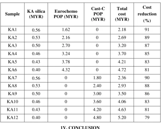
be achieved with the application of the 6 kg of low cost molds at various POP content. It has been found that the cost of molding can be reduced by 79 - 91% subject to the type and content of silica and POP. Since the price of JB silica and KA silica is the same, cost reduction by using these two sands is equivalent.
Table III: Cost of Molding and Cost Reduction
Sample KA silica (MYR) Eurochemo POP (MYR) Cast-C POP (MYR) Total cost (MYR) Cost reduction (%)
KA1 0.56 1.62 0 2.18 91 KA2 0.53 2.16 0 2.69 89 KA3 0.50 2.70 0 3.20 87 KA4 0.46 3.24 0 3.70 85 KA5 0.43 3.78 0 4.21 83 KA6 0.40 4.32 0 4.72 81 KA7 0.56 0 1.80 2.36 90 KA8 0.53 0 2.40 2.93 88 KA9 0.50 0 3.00 3.50 86 KA10 0.46 0 3.60 4.06 83 KA11 0.43 0 4.20 4.63 81 KA12 0.40 0 4.80 5.20 79
1V. CONCLUSION
Suitable dewaxing and burnout temperature is crucial to generate fully dewaxed and clean mold with the smooth surface of the cavities. The temperature of 170oC was found suitable as dewaxing temperature and by heating the molds at the temperature of 750oC for 5 hours, complete burnout of wax pattern has been effectively achieved. Rapid initial mold heating has caused the surface of mold cavities to be deteriorated, hence a rough surface of casting. Meanwhile, the insufficient burnout process has produced a defect casting with black stain on its surface. The application of cheaper molding materials can reduce the cost of block mold up to 91% and this economic factor can contribute in driving the growth of small and medium-sized copper-based casting industry.
ACKNOWLEDGEMENT
The authors would like to thank the Ministry of Science, Technology and Innovation of Malaysia (MOSTI) for the financial support.
REFERENCES
[1] S. F. Fisher and P. A. Buhrig, Science and Technology of Casting Processess, M. Srinivasan, Ed. Winchester: InTech, 2012.
[2] W. K. Luk, and B. W. Darvell, “Effect of burnout temperature on strength of phosphate-bonded investments," Journal of Dentistry,
vol. 25(2), pp. 53-160, 1997.
[3] E. P. Lautenschlager and P. Monaghan, "Titanium and titanium alloys as dental materials,” International Dental Journal, vol. 43(3), pp.
245-253, 1993.
[4] D. Ott and C. J. Raub, “Investment casting of gold jewellery," Gold Bulletin, vol. 18 (4) pp. 140-143, 1985.
[5] K. A. Guler and M. Cigdem, "Casting quality of gypsum bonded block investment casting Molds," Advanced Materials Research, vol.
445, pp. 349-354, 2012.
[6] S.L.Sin, and D. Dube, "Influence of process parameters on fluidity of investment cast AZ91D Magnesium Alloys,” Materials Science
and Engineering A, vol. 386, pp. 34-42, 2004.
[7] S. L.Sin, and D. Dube, "Tremblay An investigation on microstructural and mechanical properties of solid mold investment casting of
AZ91D magnesium alloy,” Materials Characterization, vol. 59, pp.178–187, 2008.
[8] W. Bonilla, S. H. Masood and P. Iovenitti, "An investigation of wax patterns for accuracy improvement in investment cast parts,"
International Journal of Advanced Manufacturing Technology, vol. 18 (5), pp. 348-356, 2001.
[9] S. F. Fischer, P. Schuler, B. Bayerlein, C. Fleck and P. A. Buhrig, "Some aspects of the optimization of open-pore metal foams by
introducing bio-inspired hierarchical levels,” in Proc. of 7th International Conference on Porous Metals and Metallic Foams, Busan, Korea, 2011, pp. 57-62.
[10] M. H. Idris and S. Sharif, "Evaluation of ABS patterns produced from FDM for investment casting process," in Proc. of the 9th Asia
Pasific Industrial Engineering & Management System Conference, Bali, Indonesia, 2008, pp. 1299-1304.
[11] M. C. Maguire, M. D. Baldwin and C.L. Atwood, "Fastcast: Integration and application of rapid prototyping and computational
simulation to investment casting," in Proc. of 27th International Sampe Technical Conference, Albuquerque, New Mexico, 1995, pp. 235-244.
[13] S. F. Fischer, M. Thielen, R. R. Loprang, R. Seidel, C. Fleck, T. Speck and P.A. Buhrig, "Pummels as concept generators for bomimetically-inspired low weight structures with excellent damping properties," Advanced Engineering Materials, vol. 12(12), pp. 658-663, 2010.
[14] D. W. Jones,. Thermal analysis and stability of refractory investments. J. Prosthet Dent. Vol. 18, pp. 234–41, 1967.
[15] S. Matsuya and M. Yamane, "Decomposition of gypsum bonded investments," Journal of Dental Research, vol. 60 (8), pp. 1418-1423,
1981.
[16] D. Ott, Handbook on Casting and Other Defects in Gold Jewellery Manufacture, 2nd ed., C. W. Corti, Ed. London: World Gold
Council, 2001.
[17] S. Z. Mohd Nor, R. Ismail and M. I. N. Isa, "Preliminary study on the potential of east coast of Peninsular Malaysia’s silica for
foundry: case study – Terengganu," International Journal of Material and Mechanical Engineering, vol. 1, pp. 53-56, 2012.
[18] T. Mori, "Thermal behavior of the gypsum binder in dental casting investments," Journal of Dental Research, vol. 65(6), pp. 877-884, 1986.
[19] F. R. Sias,. Lost-wax Casting: Old, New, and Inexpensive Methods, South Carolina: Woodsmere, pp. 75-80, 2005.
[20] W. K. Luk, and B. W. Darvell, "Effect of burnout temperature on strength of gypsum bonded investments,” Dentals Materials, vol. 19,