Research Article
Three-Dimensional Finite Element Analysis of Anterior Single
Implant-Supported Prostheses with Different Bone Anchorages
Fellippo Ramos Verri,
1Joel Ferreira Santiago Júnior,
2Daniel Augusto de Faria Almeida,
1Ana Caroline Gonçales Verri,
3Victor Eduardo de Souza Batista,
1Cleidiel Aparecido Araujo Lemos,
1Pedro Yoshito Noritomi,
4and Eduardo Piza Pellizzer
11Department of Dental Materials and Prosthodontics, Universidade Estadual Paulista (UNESP),
1193 Jose Bonifacio Street, 16011-010 Arac¸atuba, SP, Brazil
2Department of Health Sciences, University of Sacred Heart (USC), Bauru, SP, Brazil
3Department of Pediatric and Community Dentistry, Dental School of Arac¸atuba, Universidade Estadual Paulista (UNESP),
11011-010 Arac¸atuba, SP, Brazil
4Renato Archer Research Center (CTI), Campinas, SP, Brazil
Correspondence should be addressed to Fellippo Ramos Verri; [email protected]
Received 11 May 2015; Accepted 9 July 2015
Academic Editor: Dennis Flanagan
Copyright © 2015 Fellippo Ramos Verri et al. This is an open access article distributed under the Creative Commons Attribution License, which permits unrestricted use, distribution, and reproduction in any medium, provided the original work is properly cited.
The aim of this study was to evaluate the stress distribution of monocortical and bicortical implant placement of external hexagon connection in the anterior region of the maxilla by 3D finite element analysis (FEA). 3D models were simulated to represent a bone block of anterior region of the maxilla containing an implant (4.0×10.0 mm) and an implant-supported cemented metalloceramic crown of the central incisor. Different techniques were tested (monocortical, bicortical, and bicortical associated with nasal floor elevation). FEA was performed in FEMAP/NeiNastran software using loads of 178 N at 0∘, 30∘, and 60∘in relation to implant long axis. The von Mises, maximum principal stress, and displacement maps were plotted for evaluation. Similar stress patterns were observed for all models. Oblique loads increased the stress concentration on fixation screws and in the cervical area of the implants and bone around them. Bicortical technique showed less movement tendency in the implant and its components. Cortical bone of apical region showed increase of stress concentration for bicortical techniques. Within the limitations of this study, oblique loading increased the stress concentrations for all techniques. Moreover, bicortical techniques showed the best biomechanical behavior compared with monocortical technique in the anterior maxillary area.
1. Introduction
Adequate primary stability of osseointegrated implants is considered one of the most important rules for the success of rehabilitation using dental implants [1,2]. Among factors that influence the primary stability, the bicorticalization of the implant has been considered by some studies [2, 3]. Initially, bicorticalization was used to improve the stability of implant on the bone tissue for anterior and in the posterior region of the maxilla [3], mainly for immediate loading procedures [2]. In the low-density bone (worst prognosis for osseointegration), this technique could be effective when it is
associated with underpreparation of implant socket, resulting in the increase of primary stability [4]. However, there is no consensus if this increase of primary stability could reduce the stress distribution on bone tissue.
Table 1: Description of models developed for this study.
Implant Surgical technique Loading
4.0×10.0 mm external hexagon
Model 1 0∘
Monocortical anchorage 30∘ Conventional placement 60∘
Model 2 0∘
Bicortical bone anchorage 30∘
Bicortical placement 60∘
Model 3 0∘
Bicortical bone anchorage 30∘ Bicortical placement
associated with nasal floor elevation
60∘
on occlusal and apical cortical bones and decrease of stress in the medium implant region [7–9]. Hence, advantage of bicorticalization technique is not a consensus yet.
Retrospective clinical study indicates lower survival rate of bicorticalized implants compared to monocortical implants [7]. On the other hand, clinical studies showed high predictability of implants placed at nasal floor, reach-ing survival rate of 96% in two to five years of follow-up [10]. Recently, cohort retrospective study of 32 patients that received 100 implants placed at anterior region of the maxilla associated with nasal floor elevation indicated survival rate of 100% in 27 months of follow-up. It was pointed out that this high survival rate occurred due to bicortical stabilization on nasal floor [11]. However, few studies evaluated biomechanical behavior of bicorticalization in the anterior region of the maxilla. In a biomechanical point of view, the stress distribution around bicorticalized implants is extremely relevant to indicating the best surgical technique for implant placement, mainly to predict overload tendency of implant-supported prostheses fabricated after implant placement.
Computerized simulation has been widely used for biomechanical evaluation in implantology [12–16], including some analyses of anterior region of the maxilla [17,18]. Finite element analysis (FEA) is one of the most used techniques. Thus, the aim of this study was to compare the biomechanical behaviors of single implant-supported prostheses in the anterior region of the maxilla comparing surgical techniques of implant placement.
2. Materials and Methods
2.1. Three-Dimensional Modeling. The modeling methodol-ogy was based on previous studies [12–15]. For this study three 3D models were created (Table 1, Figure 1). Each model presented a bone block of upper right central incisor area where an implant was positioned to support a single cemented crown. The implant simulated was an external hexagon implant type with dimensions of 4.0 × 10.0mm (Conex˜ao Sistemas de Pr´otese Ltda, Aruj´a, Brazil).
The geometry of bone tissue was obtained by CT-Scan recomposition of transversal images of anterior region of
Table 2: Mechanical properties of all simulated materials [14,15].
Material Elastic modulus
(𝐸– Gpa)
Poisson’s ratio (V)
Cortical bone 13.7 0.3
Trabecular bone 1.37 0.3
Titanium 110 0.35
NiCr alloy 206 0.33
Feldspathic porcelain 82.8 0.35
the maxilla by aid of InVesalius 3.0 software (CTI, S˜ao Paulo, Brazil). The finishing and simplifying of surfaces were made in Rhinoceros 4.0 software (NURBS modeling for Windows, Robert McNeel & Associates, Seattle, USA), including bone division of cortical bone layer of 1 mm surrounding tra-becular bone. The bone density was considered as type III bone [19]. Model 1 (monocortical anchorage) presented bone height of 12 mm and remaining bone of 2 mm height over the implant apex (Figures1(c)and1(f)). Model 2 (bicortical anchorage) presented bone height of 10 mm with the implant apex placed at apical cortical bone (nasal floor) (Figures1(d)
and1(g)). Model 3 (bicortical anchorage associated with nasal floor elevation) presented 8 mm of bone height remaining 2 mm of cortical bone surrounding the apex that was placed at apical area of nasal floor similarly as described by Summers for sinus lift technique (Figures1(e)and1(h)) [20].
Geometries of implant and its components (UCLA and screw) were obtained by simplification of its original design of external hexagon type (Conex˜ao Sistemas de Pr´otese Ltda., Aruj´a, Brazil) in the SolidWorks 2010 (SolidWorks Corp., Massachusetts, USA) and Rhinoceros 4.0 software (Figures
1(i),1(j), and1(l)).
Metal-ceramic crown was constructed from superficial scanning of occlusal surface of an artificial tooth (upper central incisor) obtained from a dental mannequin with the assistance of a surface scanner (3D MDX-20, Roland DG, Shizuoka-ken, Japan) according to previous studies [15]. Then, in Rhinoceros 4.0 real dimensions of the crown were established simulating an average thickness of 1 mm of felds-pathic ceramic involving the infrastructure that was joined to internal surface of UCLA modeled as cited previously
(Figure 1(k)). The modeled crown was positioned together
with the implant and screw in the bone block.
2.2. Finite Element Analysis Configuration. All geometries were exported to FEMAP 11.0 software (Siemens PLM Soft-ware Inc., California, USA) for finite element preprocessing phase. The meshes were obtained using parabolic solid elements (Figures 1(b)–1(l)). Mechanical properties of all simulated materials were attributed to the generated meshes according to literature data (Table 2) and all materials were considered isotropic, homogeneous, and linearly elastic.
Solid modeling—conventional model
(a)
Mesh sample—conventional model
(b)
Cortical bone— conventional model
(c)
Cortical bone— bicortical model
(d)
Cortical bone— nasal floor elevation
(e)
Trabecular bone— conventional model
(f)
Trabecular bone— bicortical model
(g)
Trabecular bone—nasal floor elevation
(h)
Implant
(i)
UCLA
(j)
Crown
(k)
Screw
(l)
Fighre 1: Solid modeling and generated mesh samples of all structures. (a) Modeling of model 1; (b) meshes of model 1; (c) mesh of cortical bone of model 1; (d) mesh of cortical bone of model 2; (e) mesh of cortical bone of model 3; (f) mesh of trabecular bone of model 1; (g) mesh of trabecular bone of model 2; (h) mesh of trabecular bone of model 3; (i) mesh of implant of all models; (j) mesh of UCLA of all models; (k) mesh of crown of all models; (l) mesh of screw of all models.
region for each model. The applied force was 178 N, at 0∘, 30∘, and 60∘, in relation to implant long axis at palatine surface of the incisor according to reference study [18].
NeiNastran 11 software (Noran Engineering, Inc., Cal-ifornia, USA) performed the finite element solutions. All solutions were exported to FEMAP 11.0 for postprocessing and visualization of stress maps and displacement values in areas of interest for analysis. The solid mesh convergence error values were obtained for all structures of interest to the study and can be seen inTable 3.
2.3. Criteria of Stress Analysis. Displacement patterns were used to verify the tendency of movement of all models. Some values (in millimeters) of specific areas were obtained for comparison between models. Maximum principal stress was used to analyze stress on bone tissue as recommended to analyze compression and traction patterns of friable materials [12–16]. The von Mises stress was used to analyze implants and its components as recommended to analyze ductile solid materials [14, 15]. Both analyses have units in Mega Pascal (MPa).
3. Results
3.1. von Mises Stress Analysis. The von Mises criteria showed stress concentration near UCLA/implant interface and in the fixation screw. The pattern of distribution was similar for all
models. However, the increase of loading direction (0∘to 60∘) generated higher stress concentrations. No differences of von Mises stress were observed among models in the cervical region of the implant/crown. Apical region of the implant of bicortical technique associated with nasal floor elevation presented less concentration of stress (Figure 2).
3.2. Maximum Principal Stress Analysis. In general, stress of compression was located at buccal side of the bone in contact with the cervical collar of the implant and stress of traction was located in the opposite side (Figures3and 4). Sagittal view (Figure 3) showed similar patterns of stress distribution for all techniques, mainly near to implant neck area. The bicortical techniques showed higher stress concentration of traction on bone in the implant apex area as compared to that of monocortical technique. The increase of the loading inclination (0∘ to 60∘) showed higher stress concentration, reaching over 100 MPa in some areas including the area surrounding the collar of the implant.
Table 3: Solid mesh convergence error.
Models Loading Implant Screw Cortical bone Trabecular bone
Conventional technique
0∘ 0,00026 0,00011 0,00024 0,00008
30∘ 0,00390 0,00442 0,00159 0,00014
60∘ 0,00870 0,00970 0,00280 0,00018
Bicortical technique
0∘ 0,00033 0,00011 0,00043 0,00004
30∘ 0,00409 0,00465 0,00209 0,00012
60∘ 0,00947 0,01032 0,00381 0,00018
Nasal floor elevation
0∘ 0,00030 0,00012 0,00045 0,00006
30∘ 0,00416 0,00477 0,00218 0,00014
60∘ 0,00944 0,01056 0,00333 0,00019
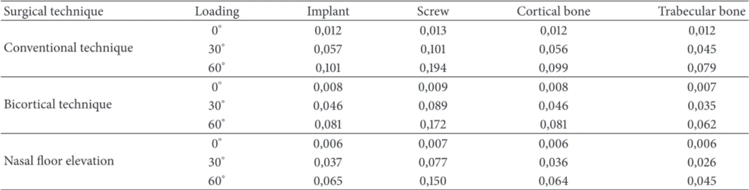
Table 4: Description values of models (in millimeter).
Surgical technique Loading Implant Screw Cortical bone Trabecular bone
Conventional technique
0∘ 0,012 0,013 0,012 0,012
30∘ 0,057 0,101 0,056 0,045
60∘ 0,101 0,194 0,099 0,079
Bicortical technique
0∘ 0,008 0,009 0,008 0,007
30∘ 0,046 0,089 0,046 0,035
60∘ 0,081 0,172 0,081 0,062
Nasal floor elevation
0∘ 0,006 0,007 0,006 0,006
30∘ 0,037 0,077 0,036 0,026
60∘ 0,065 0,150 0,064 0,045
3.3. Displacement Analysis. All models presented similar pattern of displacement distribution (Figure 5). The increase of the loading inclination (0∘ to 60∘) tends to increase the displacement tendency. Bicortical technique associated with nasal floor elevation showed smallest values for all analyzed regions followed by bicortical technique and conventional technique (Table 4). In some regions, as cortical bone, the reduction of displacement tendency was 50% for bicortical technique association with nasal floor elevation as compared to that for conventional technique.
4. Discussion
In this study, bicorticalization techniques seemed more effective biomechanically because they reduced the stress distribution in the bone tissue in the area around collar of the implant and showed less tendency of displacement. Literature has emphasized the importance of primary stability for osseointegration, mainly due to favoring the osteogenesis and bone turnover [2]. Therefore, adequate primary stability is an indispensable condition for surgical procedures of implant placement [2], principally in clinical situation of immediate loading of implants [21]. Consider that bicorticalization increases significantly the removal torque as compared to that of monocortical anchorage of implants [2]; consequently, there is an improvement of biomechanical stability using bicortical technique [22].
Bicorticalization techniques offered possibility of trans-mission of stress to upper cortical bone (in the nasal floor) dissipating stress transferred by occlusal loading. Thus,
bicorticalized bone tissue could act as biologic mechanism to prevent occlusal overload [23]. Similar methodology indicated higher stress reduction of bicortical technique as compared to that of monocortical anchorage technique [24]. This information agrees with Huang et al., 2009 [25], who demonstrated that a bicorticalized implant of≥8.5 mm-long decreased the stresses in both cortical and trabecular bone by 50% compared to a monocortical implant. Thereby, benefits of bicorticalization are expected such as reduction of stress levels in low quality bone as found in the anterior region of the maxilla and this occurred in this study.
Monocortical technique
Bicortical technique
Bicortical technique associated with nasal floor elevation
800 500 200 150 100 90 80 70 60 50 40 30 20
17.14 14.29 11.43 8.571 5.714 2.857
0
L
o
adin
g
60
∘
L
o
adin
g
30
∘
L
o
adin
g
0
∘
100 80 60 50 45 40 35 30 25 20 15 10 8 6 4 2 0 Monocortical
technique
Bicortical technique
Bicortical technique associated with nasal floor elevation
L
o
adin
g
60
∘
L
o
adin
g
30
∘
L
o
adin
g
0
∘
−3.3 −6.6 −10
L
in
gual side
B
u
ccal side
Fighre 3: Maximum principal stress analysis of bone tissue in sagittal view for different techniques.
Despite disuse atrophy cited in adjacent areas of cortical bones locked by an implant [7,9] our results showed higher levels of stress concentrations localized at upper cortical bone with no significant differences in stress patterns of trabecular bone, showing only slight reduction in tractive stress when considering bicortical technique in the lingual region of cortical bone. Thus, considering finite element analysis as a static analysis, it is not possible to determine biological evidences, as well as correlation with disuse atrophy, as suggested by some studies [7–9].
100 80 60 50 45 40 35 30 25 20 15 10 8 6 4 2 0
technique technique nasal floor elevation
L
o
adin
g
60
∘
L
o
adin
g
30
∘
L
o
adin
g
0
∘
−3.3 −6.6 −10
Dist
al side
Buccal side
M
esial side
Lingual side
Fighre 4: Maximum principal stress analysis of cortical bone in occlusal view for different techniques.
several troubles are reported regarding this technique as bleeding, swelling, pain, hematoma, graft infection, implant displacement, rhinitis, and sinusitis [11,27,28]. Certainly, any of these situations mentioned will not result in a good bone graft.
Although citations of bicorticalized implants have less survival rate by some studies [7] and good predictability by others [10], even increasing the survival rate [11], no analysis of bruxism, antagonist arch, cantilever extension, parafunctions, or other factors was investigated. Therefore, results of these studies could be carried out carefully. In this study it was indicated that bicorticalized implants are mechanically viable as rehabilitation option.
FEA studies possess limitations since it is a computational simulation and factors as restrictions of models, materials
properties, load values, and application type could change the results and are limited as compared to clinical evaluations. However, this technique allows adequate biomechanical comparative study of regions of bone/implant interface in different situations, suggesting the more suitable situation under a biomechanical point of view. Controlled randomized clinical trials should be performed to evaluate and compare the described technique.
5. Conclusions
Considering the limitations of this study
Monocortical technique
Bicortical technique
Bicortical technique associated with nasal floor elevation
L
o
adin
g
60
∘
L
o
adin
g
30
∘
L
o
adin
g
0
∘
0.1 0.08 0.06 0.04 0.02 0.018 0.016 0.014 0.012 0.010 0.009 0.007 0.005 0.003 0.001 0
Fighre 5: Displacement analysis of all models in sagittal view for different techniques.
(2) qualitative analysis of stress and displacement showed that bicortical techniques showed the best biome-chanical behavior compared with monocortical tech-nique in the anterior maxillary area.
Conflict of Interests
This study was supported by S˜ao Paulo Research Foundation, FAPESP (no. 11/01045-2 and no. 09/16164-7).
References
[1] M. Degidi, G. Daprile, and A. Piattelli, “Determination of primary stability: a comparison of the surgeon’s perception and objective measurements,”The International Journal of Oral &
Maxillofacial Implants, vol. 25, no. 3, pp. 558–561, 2010.
[2] S.-J. Ahn, R. Leesungbok, S.-W. Lee, Y.-K. Heo, and K. L. Kang, “Differences in implant stability associated with various methods of preparation of the implant bed: anin vitrostudy,”
Journal of Prosthetic Dentistry, vol. 107, no. 6, pp. 366–372, 2012.
[3] N. Ferrigno, M. Laureti, and S. Fanali, “Dental implants place-ment in conjunction with osteotome sinus floor elevation: a 12-year life-table analysis from a prospective study on 588 ITI implants,”Clinical Oral Implants Research, vol. 17, no. 2, pp. 194– 205, 2006.
[4] H. Martinez, M. Davarpanah, P. Missika, R. Celletti, and R. Lazzara, “Optimal implant stabilization in low density bone,”
Clinical Oral Implants Research, vol. 12, no. 5, pp. 423–432, 2001.
[5] S. Tada, R. Stegaroiu, E. Kitamura, O. Miyakawa, and H. Kusakari, “Influence of implant design and bone quality on stress/strain distribution in bone around implants: a 3-dimensional finite element analysis,”International Journal of
Oral and Maxillofacial Implants, vol. 18, no. 3, pp. 357–368, 2003.
[6] C.-L. Lin, J.-C. Wang, L. C. Ramp, and P.-R. Liu, “Biomechanical response of implant systems placed in the maxillary posterior region under various conditions of angulation, bone density, and loading,”International Journal of Oral and Maxillofacial
Implants, vol. 23, no. 1, pp. 57–64, 2008.
[7] C.-J. Ivanoff, K. Gr¨ondahl, C. Bergstr¨om, U. Lekholm, and P.-I. Br˚anemark, “Influence of bicortical or monocortical anchorage on maxillary implant stability: a 15-year retrospective study of Branemark System implants,”International Journal of Oral and
Maxillofacial Implants, vol. 15, no. 1, pp. 103–110, 2000.
[8] N. L. Clelland, J. K. Lee, O. C. Bimbenet, and A. Gilat, “Use of an axisymmetric finite element method to compare maxillary bone variables for a loaded implant.,”Journal of Prosthodontics, vol. 2, no. 3, pp. 183–189, 1993.
[9] M. R. Rieger, M. Mayberry, and M. O. Brose, “Finite element analysis of six endosseous implants,” Journal of Prosthetic
Dentistry, vol. 63, no. 6, pp. 671–676, 1990.
[10] P. I. Br˚anemark, R. Adell, T. Albrektsson, U. Lekholm, J. Lindstr¨om, and B. Rockler, “An experimental and clinical study of osseointegrated implants penetrating the nasal cavity and maxillary sinus,”Journal of Oral and Maxillofacial Surgery, vol. 42, no. 8, pp. 497–505, 1984.
[11] Z. Mazor, A. Lorean, E. Mijiritsky, and L. Levin, “Nasal floor elevation combined with dental implant placement,”Clinical
Implant Dentistry and Related Research, vol. 14, no. 5, pp. 768–
771, 2012.
[12] D. A. de Faria Almeida, E. P. Pellizzer, F. R. Verri, J. F. Santiago Jr., and P. S. P. de Carvalho, “Influence of tapered and external hexagon connections on bone stresses around tilted dental implants: three-dimensional finite element method with statistical analysis,”Journal of Periodontology, vol. 85, no. 2, pp. 261–269, 2014.
[13] J. F. Santiago Junior, E. P. Pellizzer, F. R. Verri, and P. S. P. de Carvalho, “Stress analysis in bone tissue around single implants
element study,”Materials Science and Engineering C, vol. 33, no. 8, pp. 4700–4714, 2013.
[14] F. Ramos Verri, J. F. Santiago Junior, D. A. de Faria Almeida et al., “Biomechanical influence of crown-to-implant ratio on stress distribution over internal hexagon short implant: 3-D finite element analysis with statistical test,”Journal of
Biome-chanics, vol. 48, no. 1, pp. 138–145, 2015.
[15] F. R. Verri, V. E. D. S. Batista, J. F. Santiago Jr., D. A. D. F. Almeida, and E. P. Pellizzer, “Effect of crown-to-implant ratio on peri-implant stress: a finite element analysis,”Materials
Science & Engineering C: Materials for Biological Applications,
vol. 45, pp. 234–240, 2014.
[16] C. Akay and S. Yalug, “Biomechanical 3-dimensional finite element analysis of obturator protheses retained with zygomatic and dental implants in maxillary defects,” Medical Science
Monitor, vol. 21, pp. 604–611, 2015.
[17] A. Caglar, B. T. Bal, C. Aydin, H. Yilmaz, and S. Ozkan, “Evaluation of stresses occurring on three different zirconia dental implants: three-dimensional finite element analysis,”The
International Journal of Oral & Maxillofacial Implants, vol. 25,
no. 1, pp. 95–103, 2010.
[18] M.-L. Hsu, F.-C. Chen, H.-C. Kao, and C.-K. Cheng, “Influence of off-axis loading of an anterior maxillary implant: a 3-dimensional finite element analysis,”International Journal of
Oral and Maxillofacial Implants, vol. 22, no. 2, pp. 301–309, 2007.
[19] U. Lekholm and G. Zarb, Patient Selection and Preparation, Quintessence, Chicago, Ill, USA, 1985.
[20] R. B. Summers, “The osteotome technique: part 3—less invasive methods of elevating the sinus floor,”Compendium, vol. 15, no. 6, pp. 698–704, 1994.
[21] J. R. Strub, B. A. Jurdzik, and T. Tuna, “Prognosis of immediately loaded implants and their restorations: a systematic literature review,”Journal of Oral Rehabilitation, vol. 39, no. 9, pp. 704– 717, 2012.
[22] J. R. Xiao, Y. Q. Li, S. M. Guan et al., “Effects of lateral cortical anchorage on the primary stability of implants subjected to controlled loads: an in vitro study,”British Journal of Oral and
Maxillofacial Surgery A (Scotland), vol. 50, no. 2, p. 161, 2012.
[23] H. Van Oosterwyck, J. Duyck, J. V. Sloten et al., “The influence of bone mechanical properties and implant fixation upon bone loading around oral implants,”Clinical Oral Implants Research, vol. 9, no. 6, pp. 407–418, 1998.
[24] S.-H. Chang, C.-L. Lin, Y.-S. Lin, S.-S. Hsue, and S.-R. Huang, “Biomechanical comparison of a single short and wide implant with monocortical or bicortical engagement in the atrophic posterior maxilla and a long implant in the augmented sinus,”
The International Journal of Oral & Maxillofacial Implants, vol.
27, no. 6, pp. e102–e111, 2012.
[25] H.-L. Huang, L.-J. Fuh, C.-C. Ko, J.-T. Hsu, and C.-C. Chen, “Biomechanical effects of a maxillary implant in the augmented sinus: a three-dimensional finite element analysis,”The
Interna-tional Journal of Oral & Maxillofacial Implants, vol. 24, no. 3, pp.
455–462, 2009.
[26] S. Inglam, S. Suebnukarn, W. Tharanon, T. Apatananon, and K. Sitthiseripratip, “Influence of graft quality and marginal bone loss on implants placed in maxillary grafted sinus: a finite element study,”Medical and Biological Engineering and
[27] G. Felisati, M. Chiapasco, P. Lozza et al., “Sinonasal com-plications resulting from dental treatment: outcome-oriented proposal of classification and surgical protocol,”The American
Journal of Rhinology & Allergy, vol. 27, no. 4, pp. e101–e106, 2013.
Submit your manuscripts at
http://www.hindawi.com
Hindawi Publishing Corporation
http://www.hindawi.com Volume 2014
Oral Oncology
Journal ofDentistry
International Journal ofHindawi Publishing Corporation
http://www.hindawi.com Volume 2014
Hindawi Publishing Corporation
http://www.hindawi.com Volume 2014
International Journal of
Biomaterials
Hindawi Publishing Corporation
http://www.hindawi.com Volume 2014
BioMed
Research International Hindawi Publishing Corporation
http://www.hindawi.com Volume 2014
Case Reports in
Dentistry
Hindawi Publishing Corporation
http://www.hindawi.com Volume 2014
Oral Implants
Journal ofHindawi Publishing Corporation
http://www.hindawi.com Volume 2014
Anesthesiology Research and Practice
Hindawi Publishing Corporation
http://www.hindawi.com Volume 2014 Radiology
Research and Practice Environmental and
Public Health Journal of
Hindawi Publishing Corporation
http://www.hindawi.com Volume 2014
The Scientific
World Journal
Hindawi Publishing Corporationhttp://www.hindawi.com Volume 2014
Hindawi Publishing Corporation
http://www.hindawi.com Volume 2014
Dental Surgery
Journal ofDrug Delivery
Journal of Hindawi Publishing Corporationhttp://www.hindawi.com Volume 2014
Hindawi Publishing Corporation
http://www.hindawi.com Volume 2014
Oral Diseases
Journal ofHindawi Publishing Corporation
http://www.hindawi.com Volume 2014 Computational and Mathematical Methods in Medicine
Scientifica
Hindawi Publishing Corporation
http://www.hindawi.com Volume 2014
Pain
Research and Treatment
Hindawi Publishing Corporation
http://www.hindawi.com Volume 2014 Hindawi Publishing Corporation
http://www.hindawi.com Volume 2014
Endocrinology
International Journal ofHindawi Publishing Corporation
http://www.hindawi.com Volume 2014
Hindawi Publishing Corporation
http://www.hindawi.com Volume 2014
![Table 2: Mechanical properties of all simulated materials [14, 15].](https://thumb-eu.123doks.com/thumbv2/123dok_br/16346958.189290/2.900.76.437.132.367/table-mechanical-properties-simulated-materials.webp)