João Paulo da Silva-Neto(a) Marcele Jardim Pimentel(a) Flávio Domingues das Neves(b) Rafael Leonardo Xediek Consani(a) Mateus Bertolini Fernandes dos Santos(a)
(a) Department of Prosthodontics and Periodontology, Piracicaba Dental School, Universidade Estadual de Campinas - Unicamp, Piracicaba, SP, Brazil.
(b) Department of Occlusion, Fixed Prostheses, and Dental Materials, Uberlândia School of Dentistry, Universidade Federal de Uberlândia - UFU, Uberlândia, MG, Brazil.
Corresponding Author:
Mateus Bertolini Fernandes dos Santos E-mail: [email protected]
Stress analysis of different
configurations of 3 implants to support
a fixed prosthesis in an edentulous jaw
Abstract: This study’s aims was to evaluate the stress distribution in a mandibular implant-supported prosthesis and peri-implant bone consid-ering implant quantity, diameter and position using linear 3-D inite ele-ment analysis. Models of an anterior jaw comprised 4 groups according to implant quantity, diameter, and position: control group C, 5 regular implants; R, 3 regular implants; W, 3 wide implants; and DTR, 3 regu-lar implants with the distal ones tilted 30° distally. The cantilever was loaded with an axial load of 50 N. Data was evaluated using von Mises stress on implants and maximum principal stress and microstrain on the bone. The W group showed the lowest value of maximum principal stress in peri-implant bone of the loaded side (4.64 MPa) when compared to C (5.27 MPa), DTR (5.94 MPa), and R (11.12 MPa). Lower stress values in the loaded implants were observed in the experimental groups when compared to the C group. However, the unloaded implants presented op-posite results. All the screws of the W group presented lower stress values when compared to the C group. However, the R and DTR groups pre-sented an increase in stress values with the exception of the loaded screw. A reduction in the number of implants associated with wider implants reduced the stress in the bone and prosthetic components.
Descriptors: Dental Implants; Jaw, Edentulous; Finite Element Analysis.
Introduction
Fixed implant-supported prostheses have shown clinical success and proven functional beneits for use in the edentulous mandible.1,2 Changes
in the original protocol have been proposed to simplify and optimize the rehabilitation of edentulous patients, increasing access to treatment.3-9
Branemark et al.3 initially proposed the use of 3 wide implants to
sup-port a ixed implant-supsup-ported prosthesis in the edentulous mandible, obtaining a success rate of 98% over 3 years of follow-up. However, this rehabilitation did not achieve similar results compared to conven-tional implant-support rehabilitations with immediate loading.3,8,10
Con-sequently, this therapy is not often prescribed. The unfavorable results were attributed to the angulation of the implants during the surgical pro-cedure and the dificulty in obtaining a passive it with the prefabricated metallic frameworks.8,9
Based on the Novum protocol, Branemark3 developed a new proposal Declaration of Interests: The authors
certify that they have no commercial or associative interest that represents a conflict of interest in connection with the manuscript.
Submitted: May 07, 2013
Accepted for publication: Aug 12, 2013 Last revision: Sep 03, 2013
for a complete ixed mandibular implant-supported prosthesis. This option aimed to provide a less ex-pensive ixed implant-supported prosthesis and a simpliied surgical procedure, which could be ap-plied to a broader range of edentulous patients. This new concept of prosthetic rehabilitation consists of a complete ixed mandibular prosthesis supported by 3 implants splinted with a manufactured metal framework, subjected to immediate loading. Im-plants are placed between the mental foramina. Two distal implants are placed next to the foramina, and a single central implant is placed at the midline.9
The use of 3 regular implants in this coniguration has shown promising clinical results, with success rates above 96%.8,9 However, data on the limitations
and long-term complications of these rehabilitations are still insuficient.8,9
Increasing the implant diameter and tilting the distal implants have been proposed to improve the biomechanical behavior by increasing the contact surface area and reducing the average cantilever length of the prosthesis.5-7,11,12 However, it is
un-clear how the number, diameter, and arrangement of the implants impact the biomechanical behavior of ixed implant-supported complete dentures. Giv-en the absGiv-ence of experimGiv-ental studies that support the clinical use of this coniguration, the aim of this study was to use linear three-dimensional (3D) i-nite element (FE) analysis to evaluate the stress dis-tribution in the peri-implant bone and prosthetic components with different implant conigurations. The hypothesis was that the stress distribution in a ixed implant-supported prosthesis is inluenced by the number, diameter, and arrangement of im-plants.
Methodology
A 3D modeling software (SolidWorks 2010, SolidWorks Corp., Concord, USA) was used to build a model of a severely resorbed jaw, with exter-nal hex titanium implants (10.0 mm length) between the mental foramens and a ixed implant-supported prosthesis seated on the implants by UCLA abut-ments and a titanium metal bar (5.0 mm diameter). Models were divided into 4 groups according to the number, diameter, and arrangement of the implants.
The control group had 5 regular implants, arranged in parallel; the regular implants group had 3 regular implants, arranged in parallel; the distally tilted reg-ular implants (DTRI) group had 3 regreg-ular implants, with the distal implants tilted 30 degrees; and the wide implants group had 5 wide implants, arranged in parallel. Regular and wide implants measured 3.75 and 5.0 mm in diameter, respectively. The bar was the same for all groups. The cantilever exten-sion was 15 mm for the control, regular implants, and wide implants groups. The DTRI group had a shorter cantilever extension due to inclination of the distal implants.
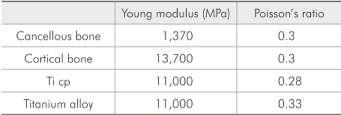
FE models were obtained by importing the mod-el into a mechanical simulation software package (ANSYS Workbench 11, Ansys Inc., Canonsburg, USA). All materials used in this study were consid-ered to be isotropic, homogeneous, and linearly elas-tic. The elastic properties used (Table 1) were taken from the literature.13-16
Convergence tests, with 6% conidence levels, were performed to guarantee that the results were not inluenced by the FE mesh. The implant thread was removed to reduce the number of elements. The elements used in the mesh were tetrahedral with 10 nodes. The inal mesh presented an ele-ment size of 0.5 mm. The number of eleele-ments and nodes generated in the FE models varied within the groups:
• control: 454,375 and 754,763;
• regular implants: 297,236 and 502,513;
• DTRI: 307,877 and 517,612;
• wide implants: 299,260 and 505,617, respective-ly).
Arrangements of the investigated models are pre-sented in Figure 1.
Table 1 - Material properties adopted in this study.
Young modulus (MPa) Poisson’s ratio
Cancellous bone 1,370 0.3
Cortical bone 13,700 0.3
Ti cp 11,000 0.28
Results
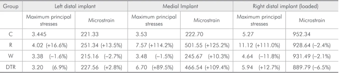
The MPS and microstrain values on the peri-implant bone are described in Table 2. The wide implants group showed the highest decrease in MPS (−11.8%) in the peri-implant bone of the loaded implant compared to the control group. The regu-lar implants group presented the highest increase in the medial implant (114.2%). The control group Constraint conditions for the displacement were
applied to the mandible base. Loads were applied unilaterally in the right cantilever (50 N). Data for von Mises stresses for implants, screws, and frameworks, and the maximum principal stresses (MPS) and microstrain for peri-implant bone were analyzed, reproduced numerically, color-coded, and compared among the groups.
Figure 1 - Three-dimensional model configurations.
Table 2 - Maximum principal stresses (MPa), microstrain values, and percentage of variance in relation to the C group in the peri-implant bone.
Group Left distal implant Medial Implant Right distal implant (loaded)
Maximum principal
stresses Microstrain
Maximum principal
stresses Microstrain
Maximum principal
stresses Microstrain
C 3.445 221.33 3.53 222.70 5.27 952.34
R 4.02 (+16.6%) 251.34(+13.5%) 7.57(+114.2%) 501.55(+125.2%) 11.12(+111.0%) 928.64(−2.4%)
W 3.38 (−1.6%) 215.16 (−2.7%) 3.48 (−1.5%) 245.67 (+10.3%) 4.64 (−11.8%) 931.49(−2.1%)
DTR 3.20 (6.9%) 227.56 (+2.8%) 6.70 (+89.5%) 466.54(+109.4%) 5.94 (+12.7%) 889.79(−6.5%)
C R
presented the highest stress value in the right distal implant (loaded; 62.41 MPa), whereas the regular implants group presented a slight decrease (−0.5%) and the DTRI (−27.2%) and wide implants (−41.2%) groups had larger reductions in stress values.
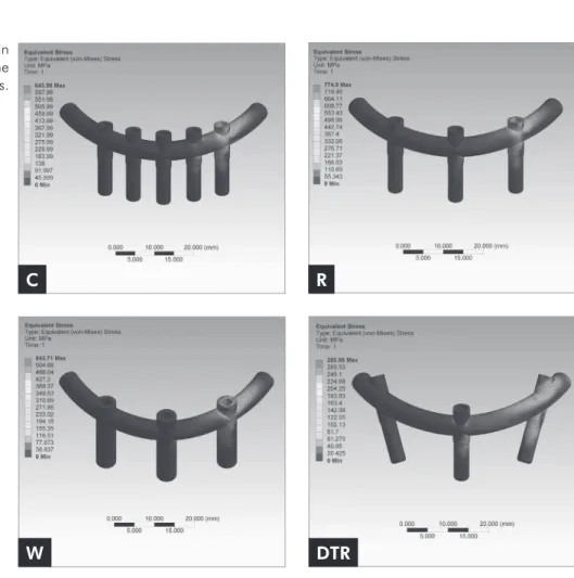
In all analyzed models, stresses were concentrat-ed in the cortical bone near the implant platform. The highest stress values were observed adjacent to the load application. The stress values decreased progressively as the components were located fur-ther from the load (Table 3 and Figure 2).
As shown in Table 4, the wide implants group presented a reduction in the stress values in all
screws compared to the control group. However, both arrangements (parallel and tilted implants) with 3 implants of regular diameter presented an increase in stress values, except for the right distal screw (loaded) in the DTRI group.
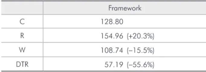
The stress distribution in the framework is pre-sented in Table 5. The DTRI group prepre-sented the lowest and the regular implants group the highest value of stress.
Discussion
The hypothesis of this study was partially con-irmed. Reducing the number of implants from 5
Left distal implant Medial implant Right distal implant (loaded)
C 5.16 11.27 62.41
R 9.00 (+74.3%) 23.17(+105.5%) 62.07 (−0.5%)
W 5.94 (+15.0%) 14.53 (+28.8%) 36.66 (−41.2%)
DTR 8.89 (+72.3%) 18.14 (+60.9%) 45.42 (−27.2%) Table 3 - von Mises stresses
(MPa) and percentage of variance in relation to the C group in the implants.
Figure 2 - Stress distribution in the prosthetic components on the different groups.
C R
(control group) to 3 (regular implants group) in-creased the stress in the peri-implant bone, implants (except the loaded implant), screws, and frame-work. However, the stress values were reduced for the wide implants group, which had fewer implants of greater diameter compared to the control group. These results corroborate the indings proposed by the Novum concept.17 Thus, although high clinical
success rates have been obtained for mandibular implant-supported rehabilitations using 3 implants, the use of regular implants in this setting can pos-sibly overload the components, resulting in higher rates of screw loosening, which leads to a greater need for more follow-up appointments.
The possibility of reducing the number of im-plants was based on the distribution of load be-tween them. According to Duyck et al.,18 the distal
and central implants receive the greatest loads, re-gardless of the number of implants between them or the total number of implants. Such indings sug-gest that it is not necessary to use a large number of implants to support a mandibular ixed implant-supported prosthesis.9 In the present study, the
regular implants group showed the highest stress values in the peri-implant bone. The stress in the peri-implant bone was higher as it approached the region of load application, whereas the unloaded distal implant presented the lowest stress values for all groups.
When the DTRI group was compared to the reg-ular implants group, the tilted implants were even more important in decreasing stress on the loaded region. These indings conirm previous evalua-tions of mandibular ixed rehabilitaevalua-tions support-ed by 4 implants. Those previous studies found a stress reduction when the distal implants were tilted about 30°–45°, due to a reduction in the lever arm and largest cortical bone area for stress
distribu-tion.4,6,7,12 Nevertheless, the DTRI group presented
higher levels of stresses in the peri-implant area of the loaded side when compared to the control and wide implants groups. In the screws and framework, components next to the loaded region presented higher stress values than the distant ones. The regular implants group showed the highest values for both screws and framework. The DTRI group presented increased stress values in the unloaded screws (medial and left distal), but the loaded screws had decreased stress values compared to the con-trol group. The reduction in the number of implants could be a risk factor facilitating screw loosening or fracture.18 A decrease in the number of implants
with maintenance of the implant diameter led to a relevant increase in stress in the prosthetic compo-nents. Similar studies evaluating the quantity and arrangement of implants did not evaluate prosthetic components.7,12 Thus, there are few data to allow
comparisons.
The unloaded implants and screws of the DTRI group showed increased stress values compared to the control group, perhaps due to the reduction in the number of the implants and the dissipation of stress in the entire system. Although high stress concentrations could lead to long-term fatigue fail-ure,8,9 the increased stress values were still lower
than those observed in the regular implants group.
Table 5 - von Mises (MPa) stresses and percentage of vari-ance in relation to the C group in the framework.
Framework
C 128.80
R 154.96 (+20.3%)
W 108.74 (−15.5%)
DTR 57.19 (−55.6%)
Left distal screw Medial screw Right distal screw (loaded)
C 1.91 5.81 19.136
R 2.84 (+48.4%) 11.45 (+97.1%) 21.69 (+13.3%)
W 1.17 (−38.6%) 4.97 (−14.3%) 15.04 (−21.3%)
DTR 2.74 (+43.1%) 9.55 (+64.4%) 18.30 (−4.3%) Table 4 - von Mises (MPa) stresses
The increase in diameter is more relevant to increas-ing the peri-implant bone surface than the implant length. Larger peri-implant bone surface areas pro-vide greater dissipation of stresses when a prosthesis is loaded. In some cases, this situation can compen-sate for a reduced number of implants in prosth-odontic rehabilitations.19-21 Similarly, in this study, a
reduction in the number of implants associated with an increase in the implant diameter did not inlu-ence the stress and strain values in the peri-implant bone compared to the control group.
The wide implants group presented higher stress values in the unloaded implants compared to the control group. However, these stresses are probably supported by the implants due to their increased diameter and, as a result, the fatigue resistance is likely increased compared to regular implants.22 A
comparison of the stress values of the wide implants group with the other groups with 3 implants showed more relevant results, indicating a better stress dis-tribution.
These indings agree with the initial concerns re-ported in the development of the Novum system, which advocated a reduction in the number and an increase in the diameter of implants.3 The results
also reinforce the hypothesis that failures observed in the Novum system were possibly caused by in-adequate implant positioning during the surgical procedures, due to the dificulty in obtaining a pas-sive it with prefabricated metallic frameworks.8 The
use of wide implants in the anterior region of the mandible is a limitation on the prescription of this technique, due to the reduced bone quantity in this region. Also, the presence of type I cortical bone re-quires a change in the bone milling protocol and in-creases the risk of tissue necrosis.
In all arrangements with 3 implants, the mi-crostrain values were below levels considered harm-ful to bone.23 The load applied in this test simulated
a conventional denture as antagonist. If the load ap-plied were to be increased, as is the case with oppos-ing natural dentition or implant rehabilitations, then the stress values and strains would be more harmful to the system, possibly compromising the longevity of the therapy. Some studies have shown that the use
of 3 implants in an edentulous mandible to support a ixed prosthesis is viable, and that the stresses gen-erated during function are not suficient to damage the osseointegration. However, these stresses can still be detrimental to the long-term success of the rehabilitation.8,9
Although UCLA abutments were used in the present study, micro-units are the most commonly used abutments in clinical application. However, mi-cro-units are more expensive than UCLA abutments. Because the authors sought to evaluate the biome-chanics of various implant distributions, UCLA abutments were used to minimize the costs. Use of FE analysis helps to overcome some traditional ex-perimental methodological limitations, by offering information about the biomechanics of a given situ-ation.13-16 However, FE analysis presents some
limi-tations due to simpliications made in the analysis. The assumption of homogeneous, isotropic, and lin-early elastic properties for the bone is common in the literature,13-16 but could affect the reliability of
the results. Another limitation was the removal of the implant threads. Although a previous study ob-served that the threads inluence the biomechanical behavior,24 their removal was useful for reducing
the number of elements and nodes of the FE model. These aspects are limiting factors when the FE analy-sis comprises a large model with many components.
In this study, conventional rehabilitation with 5 implants did not present the best results for the prosthetic components and peri-implant bone. The use of 3 wide implants showed the lowest stress val-ues for components and peri-implant bone, with the exception of the framework. Further studies using implant threads, nonlinear conditions, and differ-ent methodologies, such as experimdiffer-ental studies and clinical trials, should be performed to verify the ef-fects of such arrangements on the longevity of this type of rehabilitation.
Conclusion
References
1. Branemark PI, Svensson B, van Steenberghe D. Ten-year sur-vival rates of fixed prostheses on four or six implants ad mo-dum Branemark in full edentulism. Clin Oral Implants Res. 1995 Dec;6(4):227-31.
2. Mendonca DB, Prado MM, Mendes FA, Borges TF, Mendonca G, Prado CJ, et al. Comparison of masticatory function be-tween subjects with three types of dentition. Int J Prosthodont. 2009 Jul-Aug;22(4):399-404.
3. Branemark PI, Engstrand P, Ohrnell LO, Grondahl K, Nils-son P, Hagberg K, et al. Branemark Novum: a new treatment concept for rehabilitation of the edentulous mandible. Pre-liminary results from a prospective clinical follow-up study. Clin Implant Dent Relat Res. 1999;1(1):2-16.
4. Begg T, Geerts GA, Gryzagoridis J. Stress patterns around dis-tal angled implants in the all-on-four concept configuration. Int J Oral Maxillofac Implants. 2009 Jul-Aug;24(4):663-71. 5. Takahashi T, Shimamura I, Sakurai K. Influence of number
and inclination angle of implants on stress distribution in man-dibular cortical bone with All-on-4 Concept. J Prosthodont Res. 2010 Oct;54(4):179-84.
6. Kim KS, Kim YL, Bae JM, Cho HW. Biomechanical com-parison of axial and tilted implants for mandibular full-arch fixed prostheses. Int J Oral Maxillofac Implants. 2011 Sep-Oct;26(5):976-84.
7. Fazi G, Tellini S, Vangi D, Branchi R. Three-dimensional finite element analysis of different implant configurations for a mandibular fixed prosthesis. Int J Oral Maxillofac Implants. 2011 Jul-Aug;26(4):752-9.
8. Hatano N, Yamaguchi M, Yaita T, Ishibashi T, Sennerby L. New approach for immediate prosthetic rehabilitation of the edentulous mandible with three implants: a retrospective study. Clin Oral Implants Res. 2011 Nov;22(11):1265-9. 9. Rivaldo EG, Montagner A, Nary H, da Fontoura Frasca LC,
Branemark PI. Assessment of rehabilitation in edentulous patients treated with an immediately loaded complete fixed mandibular prosthesis supported by three implants. Int J Oral Maxillofac Implants. 2012 May-Jun;27(3):695-702. 10. Engstrand P, Grondahl K, Ohrnell LO, Nilsson P, Nannmark
U, Branemark PI. Prospective follow-up study of 95 patients with edentulous mandibles treated according to the Brane-mark Novum concept. Clin Implant Dent Relat Res. 2003 May;5(1):3-10.
11. Krekmanov L, Kahn M, Rangert B, Lindstrom H. Tilting of posterior mandibular and maxillary implants for improved prosthesis support. Int J Oral Maxillofac Implants. 2000 May-Jun;15(3):405-14.
12. Bevilacqua M, Tealdo T, Pera F, Menini M, Mossolov A, Dra-go C, et al. Three-dimensional finite element analysis of load
transmission using different implant inclinations and cantile-ver lengths. Int J Prosthodont. 2008 Nov-Dec;21(6):539-42. 13. Dos Santos MB, Bacchi A, Consani RL, Mesquita MF.
Influence of thickness and area of reline on the stress dis-tribution in peri-implant bone during the healing period: a three-dimensional finite element analysis. Gen Dent. 2012 Jul-Aug;60(4):e231-6.
14. Dos Santos MB, Consani RL, Mesquita MF. Influence of dif-ferent soft liners on stress distribution in peri-implant bone tissue during healing period. A 3-D finite element analysis. J Oral Implantol. 2011 Jul 18. Epub ahead of print.
15. Dos Santos MB, Silva Neto JP, Consani RL, Mesquita MF. Three-dimensional finite element analysis of stress distribu-tion in peri-implant bone with relined dentures and different heights of healing caps. J Oral Rehabil. 2011 Sep;38(9):691-6. 16. Spazzin AO, Dos Santos MB, Correr-Sobrinho L, Consani RL,
Mesquita MF. Effects of horizontal misfit and bar framework material on the stress distribution of an overdenture-retaining bar system: a 3D finite element analysis. J Prosthodont. 2011 Oct;20(7):517-22.
17. Branemark PI. The Branemark Novum Protocol for same-day teeth. A global perspective. Berlin: Quintessence; 2000. 166 p. 18. Duyck J, Van Oosterwyck H, Vander Sloten J, De Cooman
M, Puers R, Naert I. Magnitude and distribution of occlusal forces on oral implants supporting fixed prostheses: an in vivo study. Clin Oral Implants Res. 2000 Oct;11(5):465-75. 19. Himmlova L, Dostalova T, Kacovsky A, Konvickova S.
Influ-ence of implant length and diameter on stress distribution: a finite element analysis. J Prosthet Dent. 2004 Jan;91(1):20-5. 20. Mahon JM, Norling BK, Phoenix RD. Effect of varying fixture
width on stress and strain distribution associated with an implant stack system. Implant Dent. 2000 Winter;9(4):310-20. 21. Renouard F, Nisand D. Impact of implant length and diameter
on survival rates. Clin Oral Implants Res. 2006 Oct;17 Suppl 2:35-51.
22. Friberg B, Ekestubbe A, Sennerby L. Clinical outcome of Branemark System implants of various diameters: a retro-spective study. Int J Oral Maxillofac Implants. 2002 Sep-Oct;17(5):671-7.
23. Wiskott HW, Belser UC. Lack of integration of smooth tita-nium surfaces: a working hypothesis based on strains gener-ated in the surrounding bone. Clin Oral Implants Res. 1999 Dec;10(6):429-44.