Materials Engineering, Vol. 17, 2010, No. 2
6ELASTICITY OF SHORT FIBRE REINFORCED POLYAMIDE:
MORPHOLOGICAL AND NUMERICAL ANALYSIS OF FIBRE
ORIENTATION EFFECTS
Francesca Cosmi, Andrea Bernasconi
Received 1st April 2010; accepted in revised form 12th October 2010
Abstract
The fatigue behaviour of injection moulded short fibre reinforced polymers depends upon fibre orientation, as shown in experiments conducted with notched specimens injected through different injection gates. The different fatigue behaviour is mainly related to the different local elastic properties, as determined by the different fibre orientation patterns, resulting into different strain distributions. In order to quantify the relationship between fibre orientation and elastic constants, the Cell Method was applied to volumes extracted from the specimens, reconstructed by micro-tomography.
Keywords: short fibre reinforced polyamide, Fatigue, Micro computed tomography.
1. Introduction
The mechanical behaviour of short fibre reinforced polymers (SFRP) strongly depends upon fibre orientation. Moreover, fibre orientation is related to the manufacturing process, usually injection moulding. During injection, fibres are dispersed into the molten matrix and their final orientation is the result of complex phenomena related to viscosity of the melt polymer, velocity profiles, shear flow and interactions with mould walls.
In the perspective of metal replacement by SFRP in mechanical parts, the importance of the fatigue behaviour is increasing. Like other mechanical properties, e.g. tensile modulus and strength, the fatigue behaviour depends upon fibre orientation. In the case of simple geometries and for short glass fibre reinforced (SGFR) polyamide 6, this dependence was experimentally investigated and expressed through a relationship derived from the Tsai-Hill criterion [1]. This relationship was verified for off-axis uniaxial tests on specimens extracted from injection moulded plates and assuming that mean fibre orientation coincided with the plate’s axis. Real parts display a more complex geometry, and their fatigue strength is influenced by other factors like weld lines [2] and notches [3,4].
The importance of the manufacturing process is evidenced by the different fatigue behaviours which can be observed when notched specimens of same geometry are injection moulded through different gates [4]. This appears to be due to the different fibre
orientation patterns obtained [5]. It is therefore important to be able to predict the fibre orientation in real parts, and to take into account of the effect of fibre orientation when modelling the material’s behaviour, e.g. when performing finite element analysis.
Commercial software packages exist, which allow for this operations. However, it is also necessary to define proper experimental methods to validate fibre orientation predictions, to characterize the micro structure and to relate fibre architecture to the mechanical properties of the material.
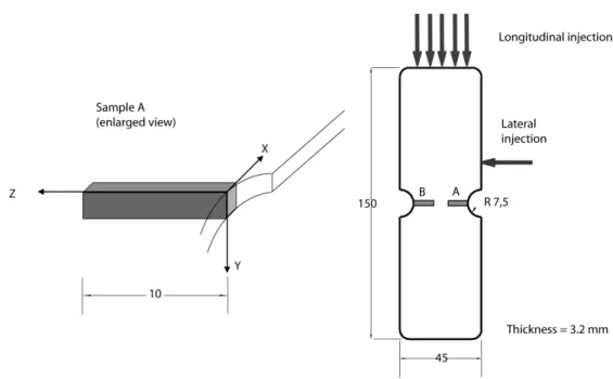
Recently, a novel technique based on micro computed tomography (micro-CT) 3D reconstruction of the fibre structure has been introduced and quantification of fibre orientation preferred directions has been shown possible by means of a global parameter, the Mean Intercept Length (MIL) [6]. By this method it is possible to analyze fibre orientation in the perspective of validating predictions by software packages simulating the injection moulding process, which often also provide estimates of the elastic constants to be assigned locally to each element in a subsequent finite element simulation. In fact, mean fibre orientation alone is not sufficient to determine the material’s elastic constants, as the local the full fibre orientation distribution must be taken into account. In this work, in order to study the effect of injection point location upon the fatigue strength of the specimens used in [4, 5] (see Fig. 1), we applied an analysis method combining micro CT and a
micro-F. Cosmi, Dipartimento di Ingegneria Meccanica, via A. Valerio 10, 34127 Trieste, Italy.
mechanical model based on the Cell Method, first introduced in [7] to examine the local properties of biological materials, subsequently [8, 9] applied to the same short glass fibre reinforced polyamide studied in [1].
2. Experimental Results
The experimental results of the tensile and fatigue tests are presented in [4, 5] and they are summarized in Fig. 2 and Fig. 3, respectively. It is clearly shown that longitudinal injection yielded higher tensile fatigue strength than lateral injection. A reduction in strength is observed with reference to standard ISO 527 specimens. The tensile strength of standard and non-standard specimens is performed by plotting the stress-time history (it is not possible to compare strain in notched and un-notched specimens if local strains at the notch root are not measured).
Fig. 2. Tensile stress-strain curves of the specimens with lateral notches, compared with that of a standard
ISO 527 specimen.
Fig. 3. S-N curves for specimens with lateral notches.
The comparison of the fatigue behaviour of notched specimens with that of standard specimens is carried out by dividing stress values by σW, the
fatigue strength of standard specimens at one million cycles. The strength decreases with reference to standard specimens is mainly due to the notch effect, but also to the orientation has to be taken into account: the fibre distribution in a standard specimen may differ from that of a notched specimen because of the changes in the mould thickness and shape. Conversely, the decrease of strength of specimens injected laterally with reference to specimens injected longitudinally is only related to the different strain distribution induced by the differences in fibre orientation. A different strain pattern was shown by experimental observations using Digital Image Correlation techniques [5]. Moreover, different fibre orientation patterns were observed in the gauge sections of two specimens injected through longitudinal and lateral gates [5, 10].
Fig. 1. Specimens type, dimensions and injection gates; position and size of micro-CT examined samples.
Materials Engineering, Vol. 17, 2010, No. 2
8The local fibre architecture was reconstructed by Micro-CT on samples extracted form the specimen in their gauge section. Micro-CTs with a resolution of 9 µm were obtained at the SYRMEP beamline of Elettra synchrotron light source (Trieste, Italy) using Phase Contrast (PHC) imaging techniques and the morphological characterization was conducted by means of the Mean Intercept Length (MIL) parameter and the MIL related fabric tensor using Quant3D software [11]. The details of the procedure are reported in [6].
In order to investigate whether the effect of the observed differences in fibre orientation distributions upon elastic modulii, samples extracted in the location A of fig.1, close to the notch, were analyzed over a 5 mm portion of the gauge section. A comparison was performed among sample A of the specimen injected longitudinally and sample A of the specimen injected through the side gate. These samples displayed the common layered structure, characterized by the presence of a shell layer, where fibres tend to align parallel to the polymer flow during injection, and a core layer usually found in the mid section of flat specimens, where under certain conditions fibres may rotate and deviate from the flow direction. In this layer the most significant differences in fibre orientation distributions were observed. A longitudinal section, corresponding to the core layer, of the reconstructed volumes is reported in Fig. 4 for both specimen types.
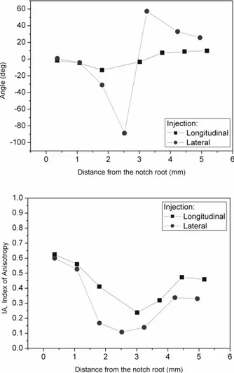
The core layer (mid plane) of each reconstructed sample was divided into a series of cubic Volumes Of Interest, VOI, 80x80x80 voxel3, that were singularly analyzed using Quant3D software. From the properties of the MIL fabric tensor evaluated by this method it is possible to define a preferred fibre orientation angle and an Index of Anisotropy IA:
IA = =1 – MIN(eigenvalues)/ MAX(eigenvalues) (1) so that IA values can vary from IA = 0 for perfect isotropy to IA =1.
Results are shown in Fig.5. It clearly appears that the location of the injection gate influences both the preferred fibre orientation angle and the index of anisotropy. In the core layer of the laterally injected specimen, it can be seen that fibres tend to make an almost full 180° rotation when observed from the notch root inwards.
In order to evaluate the effect of the observed differences in fibre orientation and degree of anisotropy upon the local elastic constants of the material, a Cell Method model was built for each VOI.
The Cell Method model has already been used for this material in [8,9] and it allowed for estimating
Fig. 4. Lateral and longitudinal injection, point A, core layer: µ-CT reconstruction.
Fig. 5. Preferred fibre orientation with respect to specimen y axis (above), and Index of Anisotropy IA
(below), at different z positions (mm), core layer.
the local values of the elastic modulii Ex, Ey and Ez.
directions of the reference frame of Fig. 1 (Ex , Ey and
Ez respectively) were computed by simulation.
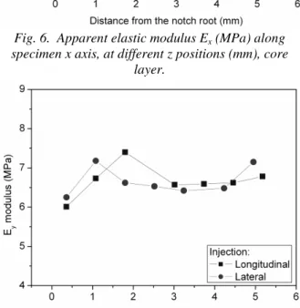
Results are shown in figures from 6 to 8. It appears that the differences in mean fibre orientation and index of anisotropy shown in Fig. 5 result into different local values of the local elastic moduli, as predicted by the Cell Method applied to the reconstructed micro-structure of the samples, particularly in the case of the Ex modulus.
Fig. 6. Apparent elastic modulus Ex (MPa) along
specimen x axis, at different z positions (mm), core layer.
Fig. 7. Apparent elastic modulus Ey (MPa) along
specimen y axis, at different z positions (mm), core layer.
These results indicate that by this method it is possible to estimate the local values of the material’s elastic modulii and relate them to the fibre distribution. Further research is required in order to explain the different fatigue behaviour. In this perspective, the information deriving from the analysis method presented herein could be used to validate the values of the elastic modulii used in finite element models, as defined on the basis of numerical simulations of the injection moulding process.
Fig. 8. Apparent elastic modulus Ez (MPa) along
specimen z axis, at different z positions (mm), core layer.
3. Conclusions
Differences have been observed in the fatigue behaviour of short fibre reinforced polyamide notched specimens depending on injection point location. These experimental results might be attributed to different strain distributions due to variations of the local apparent elastic properties along the specimen section, which in turn are closely related to changes in fibre orientation occurring during the manufacturing process and consequently to different local elastic constants. In order to precisely quantify these effects, the Cell Method applied to the micro-structure reconstructed by micro tomography was successfully applied. Further investigation is needed to confirm these preliminary results.
Acknowledgements
The authors thank Diego Dreossi and the SYRMEP staff at Sincrotrone Trieste. Radici Plastics, Italy, kindly provided the specimens used in this research. The research work is funded by the MIUR Prin 2007 program.
References
[1] Bernasconi A., Davoli P., Basile A., Filippi A.: Effect of fibre orientation on the fatigue behaviour of a short glass fibre reinforced polyamide-6. Int J Fatigue, Vol. 29 (2007) 199-208.
Materials Engineering, Vol. 17, 2010, No. 2
10[3] Sonsino CM, Moosbrugger E.: Fatigue design of highly loaded short-glass-fibre reinforced polyamide parts in engine compartments. Int J Fatigue , 30:1279-1288, 2007.
[4] A. Bernasconi, P. Davoli, C. Armanni, A. Filippi.: Effect of notches and fibre orientation on the fatigue behaviour of a short glass fibre reinforced polyamide 6. 4th Int. Conf. on Fracture of Polymers, Composites and Adhesives. Les Diablerets (CH), 2007.
[5] Bernasconi A., Cosmi F.: Combined effect of notches and fibre orientation on fatigue behaviour of short fibre reinforced polyamide. Strain (2009) in press.
[6] Bernasconi A., Cosmi F., Dreossi D.: Local anisotropy analysis in injection moulded fibre reinforced polymer composites. Composites Science and Technology, Vol. 68 (2008) 2574-2581.
[7] Cosmi, F., Dreossi, D.: Numerical and experimental structural analysis of trabecular architectures. Meccanica, Vol. 42 (2007) 85-93.
[8] Cosmi, F.: Morphological and numerical characterization of a PA6-GF 30 sample, 25th Danubia Adria Symposium, Ceske Budejovice, Czech Republic, 24-27.09.2008.
[9] Cosmi F.: Local anisotropy and elastic properties in a short glass fibre reinforced polymer composite. Strain (2009) in press.
[10]Bernasconi, F. Cosmi: Fibre orientation at notches and fatigue behaviour of short fibre reinforced polyamide. 17th Int. Conf. on Composite Materials, July 27-31, 2009, Edinburgh, UK.