Abstract
The protective capability of the Kevlar fibre-reinforced rubber composite armour (KFRRCA) at different obliquities is studied using depth-of-penetration experiments method against a 56 mm-diameter standard-shaped charge. Efficiency factors are calculated to evaluate the protection capability of the KFRRCA at different obliquities. Meanwhile, an X-ray experiment is used to observe the deformation, fracture, and scatter of the shaped-charge jet as it penetrates the composite armour. Finally, scanning electron mi-croscopy (SEM) is used to analyse the effect of the Kevlar fibre-reinforced rubber for the composite armour to resist jet penetra-tion. The results showed that the KFEECA can be used as addi-tional armour, because it has excellent protection capability, and it can disturb the stability of the middle part of the shaped charge jet (SCJ) obviously especially when the armour at 30°and 68° obliquities.
Keywords
Impact dynamics; kevlar fibre; shaped-charge jet; penetration; efficiency factors.
Performance of kevlar fibre-reinforced rubber composite armour
against shaped-charge jet penetration
1 INTRODUCTION
Shaped-charge jet (SCJ) is one of the most important components in armour weaponry that ex-hibits excellent penetration performance and can damage armoured targets effectively. One com-mon concern is protecting the armoured vehicles to reduce damage by SCJ. One effective protec-tion method used at present is disturbance of the SCJ stabilities by addiprotec-tional armour to reduce the SCJ’s penetration ability prior to attacking the main armour. Explosive reactive armours are widely used in tanks because of their excellent interference ability (Held, 1999, 2005; Yadav, 1988; Mayseless, 2011; Paik et al., 2007). However, the application of explosive reactive armour is sub-ject to certain restrictions mainly because the explosion field of the explosive reactive armour can
Xu-dong Zua Zheng-xiang Huangb Wen Zhaic
a,bSchool of Mechanical Engineering,
Nan-jing University of Science and Technology, Xiaolingwei 200, Nanjing 210094, China
azuxudong9902@mail.njust.edu.cn bhuangyue@mail.njust.edu.cn
cShandong Non-metallic Material
Latin A m erican Journal of Solids an d Structures 12 (2015) 507-519
affect the normal operation of the vehicle parts and the explosion products may injure the sol-diers around the armoured vehicles. According to the study, the bulging armour also can disturb the stability of the SCJ, and it has excellent resistance to penetration performance, so it has been widely used in the protective field of armoured vehicles, ships, and aerospace. Fibre-reinforced composite materials are widely used in the bulging armour as sandwich materials. Fibre-reinforced rubber base composite materials are materials containing fibre doped with a certain percentage of rubber to obtain specific material properties. Commonly used reinforcing fibres in-clude Kevlar, glass, carbon and ultra-high molecular weight polyethylene. Kevlar and ultra-high molecular weight polyethylene have been introduced as base materials for ballistic protection. These high performance fibers are characterized by low density, high strength, and high energy absorption (Lee et al., 2003).
Current literature indicates that rubber base composite armour can disturb SCJ stability, turning the SCJ fracture and breakage as a kind of additional armour. The description of the mechanisms of these bulging systems was first proposed by Gov et al. (1992). Yaziv compared rubber composite and explosive reactive armours, highlighting the former as superior in terms of safety and environmental effects (Yasiv et al., 1995). The study further described the process of interaction of the rubber composite armour with SCJ, but did not provide the theoretical model. Rosenberg studied the resistance capability of sandwich composite armours with different sand-wich materials through two-dimensional (2D) simulation, and considered material strength, stress modulus, and density to be the relevant factors in the resistance of composite armour to SCJ (Rosenberg and Dekel, 1998). A layer of rubber that will gasify or possibly explode is regarded as an inert explosive. A mechanism for the interaction based on the theory of Kelvin–Helmholtz instabilities was discussed by Helte and Lidén (2010a, 2010b). The process of rubber composite armour protection against SCJ penetration is divided into four parts based on the jet deformation that occurs when the SCJ penetrates the rubber composite armour. Results of the interference speed interval, interference frequency, and surplus penetration capability of the SCJ with the rubber composite armour are derived based on the stress wave and Kelvin–Helmholtz instability theory. The effects of rubber layer thickness and obliquity of the armour for the composite ar-mour anti-SCJ penetration were studied through theoretical, X-ray, and depth-of-penetration experiments by Zu et al. (2013). The protection ability of woven fabric-reinforced rubber compo-site armour as subjected to SCJ was studied by Jia et al. (2013) through experiments.
Latin A m erican Journal of Solids and Structures 12 (2015) 507-519 2 SHAPED CHARGE AND COMPOSITE ARMOUR CONDITIONS
2.1 Standard shaped-charge experiment
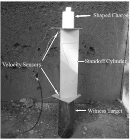
The standard shaped charge was used in this study for several reasons, such as increasing the universality of the study, simplifying the calculation of the protection, cost, and protection thick-ness coefficients, as well as considering that the standard shaped charge is often used in studies. The standard shaped charge (Figure 1, Figure 2) possessed the following characteristics: shaped-charge copper liner with 0.8 mm thickness and 56 mm diameter, as well as explosive weight of 203 g without a conical charge shell cover. The DOP experiments were set as Figure 3 to measure the standard shaped-charge jet parameters, with the 330 mm standoff and velocity sensors set at the top and the bottom of the standoff cylinder to measure the time of the shaped-charge jet tip through the standoff. A 8# flash detonator was used to detonate the SCJ. The results of the ex-periments are shown in the Table 1.
Figure 1: Photograph of the standard shaped charge with a diameter of 56 mm.
Latin A m erican Journal of Solids an d Structures 12 (2015) 507-519
The result showed the average depth of penetration to be 160 mm at the same standoff, with a relative error of approximately 5%. The depth of 160 mm was regarded as the datum plane, which is aimed at the condition of SCJ penetration of the semi-infinite steel target. The SCJ had good consistency, and the inlet diameter was almost the same as the outlet diameter. In the DOP experiments, the velocity of the shaped-charge jet tip was 6470 m/s.
No. Standoff (mm)
Time (μs)
Velocity of jet tip (m/s)
Depth of penetration (mm)
1 330 51 6470 161
2 330 51 6470 158
3 330 51 6470 160
Table 1: Results of the shaped-charge performance experiment.
Figure 3: DOP experimental setup with the velocity sensors to measure the velocity of the shaped-charge jet tip.
The jet tip and tail velocities were simultaneously measured using a multi-channel X-ray sys-tem. The double flash X-ray exposures of the shaped-charge jet at 30 and 50 μs after initiation are shown in Figure 4. The magnification of the X-ray exposures was 2.0, so the jet tip velocity was 6453 m/s and that of the tail was 1179 m/s. Comparing the velocity of the shaped-charge jet tip obtained from the X-ray exposures with that measured from the DOP experiments, the rela-tive error did not exceed 0.3%.
Latin A m erican Journal of Solids and Structures 12 (2015) 507-519 2.2 KFRRCA construction
The KFRRCA configuration comprised the following layers: Q235 steel, rubber base material doped with 15% Kevlar fibre, and Q235 steel. The thicknesses of the Q235 steel plates and rubber base material sandwich plate were 3 and 5 mm, respectively. The KFRRCA had a geometric area of 300 mm×150 mm. The Q235 steel was sandblasted, and a premium-grade adhesive was used to bond the steel plates and the Kevlar fibre-reinforced rubber plate. The parameters of the rubber, Kevlar fibre, and Q235 steel are shown in Table 2. The details of the schematic of the KFRRCA are shown in Figure 5.
Material ρ
(g/cm3)
Shore hardness Yield strength (MPa)
Tensile strength (MPa)
Elongation at failure (%)
Rubber 1.3 75 - 20 400
Kevlar fibre 1.9 - - 134 3.5
Q235 steel 7.85 - 235 375 26
Table 2: Summary of rubber, Kevlar fibre and Q235 steel parameters.
Figure 5: Schematic of the KFRRCA (all dimensions in mm).
3 DOP EXPERIMENT
3.1 DOP experiment setup
Latin A m erican Journal of Solids an d Structures 12 (2015) 507-519
Figure 6: Schematic diagram of the experimental setup.
Figure 7: DOP experimental setup with the velocity sensors to measure the velocity of the shaped-charge jet tip after penetrating the KFRRCA.
3.2 Efficiency factors
The KFFRCA was placed at a certain distance from the main armour as additional armour to improve the protection performance. The surplus depth of penetration cannot evaluate the pro-tection performance of the KFRRCA directly when the obliquity of the armour changed. Space protection coefficient (Es), quality protection coefficient (Em), and differential protection coeffi-cient (△ec) are commonly used to describe the protection level of an armour with different states,
providing information to an armour designer for armoured vehicle protection without a need to reveal details regarding the structure and mechanism of the armour systems (Zhang et al., 2000). Efficiency is always indicated in a standard or reference value.
Latin A m erican Journal of Solids and Structures 12 (2015) 507-519 △ec is the ratio between the protection ability of the sandwich material with that of the reference
armour material. 0 3 1cos st m i i st res p E h p (1) 0 0 res s p p E
p (2)
1 3 0 2 2 cos cos cos st res ec h h p p
h (3)
where ρst denotes the density of steel, ρ1 and ρ3 denote the densities of the cover plates, ρ2 denotes
the density of the sandwich material, h1 and h3 denote the thickness of the cover plates respec-tively, h2 denotes the thickness of the sandwich material, p0 denotes the depth of penetration of the standard SCJ with the 330 mm standoff, pres denotes the surplus depth of penetration of the SCJ after the jet penetrated the composite armour, and θ denotes the angle between the normal direction of the plates and the axial direction of the SCJ.
3.3 Results and discussion
The shaped-charge jet affects the witness target and produces a large number of craters. The re-sults of the impact are shown in Figure 8.
a b c
d e
Latin A m erican Journal of Solids an d Structures 12 (2015) 507-519
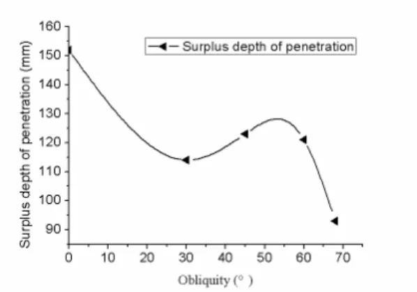
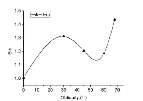
The DOP experimental results on different obliquities are shown in Figure 9 and Figure 10. The calculations of efficiency factors of different obliquities are shown in Figure 11, Figure 12 and Figure 13.
Comparing the velocity of the SCJ tip, no significant speed change was observed to correspond to the obliquity of the KFRRCA change. The thickness of the composite armour change caused by the obliquity has slight effect on the velocity of the SCJ tip. However, large differences in the surplus depth of penetration and efficiency factor were observed with the change in obliquity. Comparing the craters caused by SCJ penetration of the witness target, the KFRRCA disturbed the shaped-charge jet stability, and part of the SCJ fragmented and scattered. More expanding craters were observed on the witness target with the obliquities at 30° and 68° than in other obliquities. This result indicates that when obliquity was at 30° and 68°, the KFRRCA disturbed the shaped-charge jet more apparently, which was proven by the surplus depth of penetration and the efficiency factors. The KFRRCA had excellent protection capability when the obliquity of the armour was at 30° and 68°.
Figure 9: Relationship between velocity of jet tip and obliquity.
Latin A m erican Journal of Solids and Structures 12 (2015) 507-519 Figure 11: Relationship between quality protection coefficient of penetration and obliquity.
Figure 12: Relationship between space protection coefficient of penetration and obliquity.
Figure 13: Relationship between differential protection coefficient of penetration and obliquity.
Latin A m erican Journal of Solids an d Structures 12 (2015) 507-519 4 X-RAY EXPERIMENT
4.1 X-ray setup
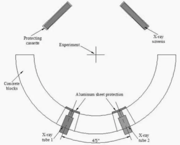
To visualise the fracture and scatter of the shaped-charge jet, the X-ray experiment method was used. The shaped charge was vertically installed in a standoff 80 mm from the KFRRCA, and the obliquity of the armour was 60° of the shaped charge axis. The shaped charge and armour were elevated using a cotton rope. In the experiment, several 450 kV multi-channel X-ray systems set at 90° were used. The experimental setup is shown in Figure 14. Through a special setting, two radiographs were obtained for the same testing. Passive detonation technology was used in the experiment to observe the deformation of the jet accurately and to eliminate the errors attributa-ble to the detonator. The image of the experimental setup is shown in Figure 15.
Figure 14: Schematic of the experiment setup of KFRRCA against a 56 mm shaped charge in front of double flash X-ray tube.
Figure 15: Image of the experiment setup with the charge on top of a KFRRCA panel. In the background are two protecting cassettes for the 860 mm-long FXR films.
4.2 Results and discussion
Latin A m erican Journal of Solids and Structures 12 (2015) 507-519 a b Figure 16: Flash X-ray radiograph of a shaped-charge jet penetrating KFRRCA under 60° at approximately
50 and 80 μs: a) 50.740 μs; b) 80.990 μs. The middle part of the shaped-charge jet was disturbed by the KFRRCA, and the middle part of the jet almost totally fragmented and scattered the jet,
which drastically reduced the latter’s penetration capability.
5 SCANNING ELECTRON MICROSCOPY (SEM) ON THE KEVLAR FIBRE-REINFORCED RUBBER
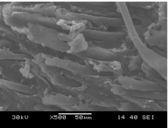
When the SCJ penetrated the KFRRCA, numerous radial cracks appeared around the crater of the rubber base sandwich rubber (Figure 17), and numerous fractured fibres can be seen around the edge of the crater on the Kevlar fibre-reinforced rubber.
Figure 17: The cracks around the crater of the rubber base sandwich rubber.
Latin A m erican Journal of Solids an d Structures 12 (2015) 507-519 c
Figure 18: SEM images for the Kevlar fibre-reinforced rubber: a) magnification 70, b) magnification 200, c) magnification 500.
The rubber material will tear and shed under the impact, but with the Kevlar fibre, the rub-ber base material around the crater was still linked around the material (Figures 17 and 18.a). The Kevlar fibres around the crater were separated with the rubber base material under the im-pact and shock wave (Figures 18.b and 18.c). Therefore, Kevlar fibre can reinforce the strength of the rubber base material and absorb shock wave energy.
6 CONCLUSIONS
A series of DOP and X-ray experiments were performed to evaluate the protection capability of the Kevlar fibre-reinforced rubber armour at different obliquities to resist Ф56 mm shaped-charge jet penetration. SEM was used to observe the deformation of the Kevlar fibre-reinforced rubber. The efficiency factors were used to evaluate the protection capability. Based on these findings, the following conclusions were drawn:
1) The Kevlar fibre-reinforced rubber enhances the strength of the rubber base material, but because the Kevlar fibre reinforced rubber has excellent performance to absorb shock waves, the deformation of the front plate of the sandwich armour is reduced, so the length of the SCJ is dis-turbed.
2) The Kevlar fibre-reinforced rubber armour has excellent protection capability, and can dis-turb the stability of the middle part of the SCJ.
3) The KFRRCA has the best protection capability with obliquities at 30° and 68°.
Acknowledgements
This research was supported by the National Natural Science Foundation of China (Grant No.11402112).
References
Latin A m erican Journal of Solids and Structures 12 (2015) 507-519 cassette. 13th Int. Symp. on Ballistics, Stockholm, Vol II: 95-99
Held, M., (1999). Comparison of explosive reactive armour against different threat levels. Propellants, Explosives, Pyrotechnics 24(2): 76-77.
Held, M., (2005). Shaped charge optimization against ERA targets. Propellants, Explosives, Pyrotechnics 30(3): 216-223.
Helte, A., Lidén, E., (2010a). The role of Kelvin-Helmholtz instabilities on shaped charge jet interaction with reactive armours plates. 25th International Symposium on Ballistics, Beijing, Vol II: 1547-1553.
Helte, A., Lidén, E., (2010b). The role of Kelvin-helmholtz instabilities on shaped charge jet interaction with reactive armor plates. Journal of Applied Mechanics 77: 051805-1-051805-8.
Jia, X., Huang, Z.X., Zu, X.D., Gu X.H., Zhu, C.S., Zhang, Z.W., (2013). Experimental study on the performance of woven fabric rubber composite armor subjected to shaped charge jet impact. International Journal of Impact Engineering 57: 134 -144.
Lee, Y. S., Wetzel, E. D., Wagner, N. J., (2003). The ballistic impact characteristics of Kevlar woven fabrics impregnated with a colloidal shear thickening fluid. Journal of materials science 38(13): 2825-2833.
Mayseless, M., (2011). Effectiveness of explosive reactive armor. Journal of Applied Mechanics 78: 051006-1-11. Paik, S. H., Kim, S.J., Yoo, Y. H., Lee, M., (2007). Protection performance of dual flying oblique plates against a yawed long-rod Penetrator. International Journal of Impact Engineering 34: 1413–1422.
Rosenberg, Z., Dekel, E., (1998). A parametric study of the bulging process in passive cassettes with 2D numerical simulations. Int. J. Impact Engineering, 21(4): 297-305
Yadav, H. S., (1988). Interaction of a metallic jet with a moving target. Propellants, Explosives, Pyrotechnics 13(3): 74-79.
Yaziv, D., Friling, S., Gov, N., (1995). The interaction of inert cassettes with shaped charge jets. 15th Int. Symp. on Ballistics, Jerusalem,Vol II: 461-467

