Structural Engineering Properties of Fibre Reinforced Concrete
Based On Recycled Glass Fibre Polymer (GFRP)
*Adetiloye A. and **Ephraim M. E.
*Department of Civil Engineering, Federal University of Agriculture Abeokuta
**Department of Civil Engineering, Rivers-State University of Science and Technology Port Harcourt.
Abstract
Glass fibre reinforced plastics (GFRP) based on resin recovered from recycling plastic waste has been shown to possess mechanical properties satisfying normative requirements. This paper investigates the flexural behavior of concrete beams reinforced with GFRP produced from resin recovered from recycled plastic wastes. A total of twelve of beams of sizes 150 ×150 ×900mm and 100 × 100 × 500mm reinforced with GFRP made from recycled glass fibre reinforced polymer was tested. The flexural test results yielded lower ultimate load, lower stiffness and larger deflections at the same load when compared with the control steel reinforced beam. However, the ultimate flexural strength of beams, reinforced with GFRP from recycled resin was at least four times higher than that of the control unreinforced beam. This is in agreement, quantitatively and qualitatively, with the trend of these parameters in GFRP reinforced concrete based on virgin resins. The results therefore confirm the applicability for structural uses of GFRP reinforcement made from recycled plastic waste, with the accompanying benefits of wealth creation, value addition and environmental sustainability.
Key Words: Concrete, Fibre reinforced plastics, composites
I.
Introduction
Fibre reinforced polymer (FRP) reinforcements has been in rapid use in concrete structures in the last decade because of it high strength, light weight, non magnetization, corrosion resistance and expected long-term durability. However, these structures are primarily based on virgin materials used as resin in the development and production of FRP reinforcements.
The current spate of deterioration of the world‟s infrastructure continues to pose serious challenges to engineering. Structures suffer from distresses due to ageing, damages due to overloading, abuse of use, war, terror and various natural disasters. Under these circumstances, it becomes increasingly imperative to determine the feasibility of utilizing high performance polymer composite materials for fabrication of new structures as well as for retrofitting the existing ones as a novel paradigm. The various reports of the American and Canadian Societies of Civil Engineers and other international professional bodies offer important recommendations on the use of high performance materials and systems in construction, citing substantial cost savings due to lower volumes of materials needed, reduced maintenance and longer lifetimes. A comprehensive review of development, mechanical properties and application of fibre reinforced polymer can be found in the publications of Ashbee (1993), ACI Reports (1996), Bakht (2000), Bakis and Wang (2002).
Investigations into the shear and flexural behavior of GFRP reinforced beams have been undertaken in several works, including those of Nawy and Neuwerth (1971), Faza and GangaRao (1992), Nanni et al. (1993), Bank and Ozel (1996), Wang and Bilarbi (2005), Al-Sunna et al (2006) and Arivalagan (2012) among others. However, these studies were all based on GFRP derived from virgin resins. There is practically no information in technical literature on the use of recycled plastic waste for structural applications.
To bridge this gap, the authors undertook a detailed study on the mechanical properties of glass fibre reinforced plastic, based on recycled resin, to assess its potentials and suitability for application in civil engineering design and construction of concrete structures. The details of this study are reported in Ephraim and Adetiloye (2014). The results from the latter study showed that recycled GFRP has a density of about 0.91-1.2 gm/cm3 within the range of fibre content of 35-50 percent. It exhibits a practically linear stress – strain relation almost to the ultimate tensile strength, averaging 43-57 MPa with a modulus of elasticity of 1.4 - 2.65 GPa. A fibre content of about 40 percent, at which the tensile strength, impact and hardness characteristics attained maximum values irrespective of laminate thickness, was established. These results confirm the applicability of GFRP from recycled resin for structural uses with the accompanying benefits of wealth creation, value addition and environmental sustainability.
This work is dedicated to the investigation of flexural behavior of concrete beams reinforced with GFRP, based on recycled resin recovered from plastic waste materials. A successful and effective incorporation of recycled GFRP as reinforcement in concrete will have the multiple benefits stated earlier as well as create jobs/employment opportunities in the construction industry. This project will also serve as a pilot effort towards the domestication of fibre reinforced polymer technology, especially in the utilization of recycled plastic waste in civil/structural engineering applications in Nigeria.
II.
Research Methodology and
Experimental Plan
The study consisted of production of the recycled GFRP and testing of concrete beams reinforced with the produced FRP reinforcement bars. Concrete beams, plain and reinforced with steel and GFRP of varying reinforcement ratios were produced and tested in the study. The beams were tested under two point loading and appropriately instrumented to record their response history up to the moment of failure. Concrete mix ratios of 1:2:4, 1:1:2 were
adopted to facilitate comparison with previous studies. The sample preparation, curing, handling and testing were conducted in accordance with BS1881, Part 1(1986). All the tests were carried out in the Structural Engineering Laboratories of the Rivers State University of Science and Technology, Port Harcourt, Nigeria.
II.1 Materials II.1.1 Concrete
The concrete was made from ordinary Portland cement meeting BS 12 (1996), locally available sand and crushed granite to the specified grading envelops of BS 882 (1992) and EC2 EN (1992). A water cement ratio of 0.55 with an average slump workability of about 50 mm, as recommended in Ephraim and Adetiloye (2015), was adopted throughout the tests. The compressive strength for the two mixes 1:1:2 and 1:2:4 averaged 38.20 N/mm2 and 21.23 N/mm2 respectively. In a related study, Arivalagan (2012) used a concrete mix ratio of 1:1:3 with a compressive strength of 30.10 N/mm2. The compressive strength values are presented in Table 1 and Figure 1.
Table 1: Compressive Strength of Concrete at Ages
Mix Ratio
Age (Days)
3 7 14 21 28
Compressive Strength Values
1:2:4 9.4 11.2 14.8 18.5 21.2
1:1:2 20.3 23.3 28.1 33.3 38.2
1:1:3 17.6 19.6 23.1 27.0 30.1
Figure 1: Plot of compressive strength with age
II.1.2 Steel reinforcement
The main reinforcement for the control beams comprised 4 nos 10 mm high tensile steel bars with yield stress of 400 MPa; the shear reinforcement was in the form of closed stirrups of diameter 6 mm and yield stress 300 MPa.
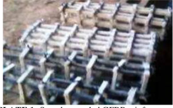
II.1.3 Glass Fibre Reinforced Polymer (GFRP) Reinforcement
The GFRP reinforcement for the study was in the formof reinforcement cages, consisting of 10 mm, 12 mm and 16 mm diameter main bars of fiber reinforced polypropylene, produced from recycled plastic and having tensile strengths of 45, 46 and 48 MPa respectively. Details of the production of the recycled polypropylene glass fibre laminates by the
hand lay-up method with ultraviolet light curing and its mechanical properties are documented in Ephraim and Adetiloye (2014). Samples of the three types of recycled GFRP cages are shown in Plate 1.
II.2 Test Specimens
A total of twelve beam specimens, grouped in two series, was tested in this study. The first series of test specimens consisted of three sets of GFRP reinforced beams and one set each of plain and steel reinforced beams. Each set comprised two similar beams. The beams in this series were 100 mm wide, 100 mm deep and 500 mm long in dimension. GFRP rebars of nominal diameters 10 mm, 12 mm and 16 mm were used with 25 mm cover and stirrups at 75mm
centre-to-centre spacing in all the beams in this series. A second set of beams was designed using data from Arivalagan (2012) with the following dimensions: 50 mm wide, 150 mm deep and 900 mm long. All the beams were tested under two-point loading. The geometric properties of the beams and the reinforcement details are given in Table 2, while Plates 2 illustrate the pictorial view of the experimental beams.
Table 2: Geometric and Reinforcement Details of Test Beams
Beam No. Beam 1 Beam 2 Beam 3 Beam 4 Beam 5 Beam 6
Rebars Plain Concrete 4
10 4
12 4
16 4
10 4
12Type of Rebars Nil GFRP GFRP GFRP Steel GFRP
Section (mm) 100x100 100x100 100x100 100x100 100x100 150x150
Reinft. Ratio % 0 3.14 4.52 8.03 3.14 2.0
PLATE 2: Beam Specimens during casting and during wet curing
III.
Experimental Set Up and Procedures
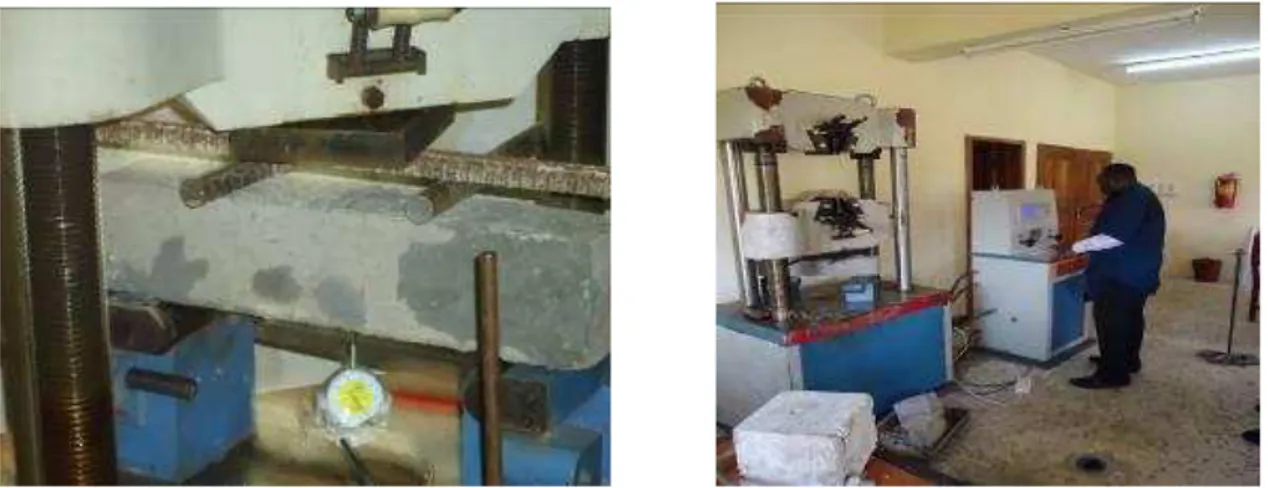
The experimental setup and instrumentation of the test beams are shown in Figure 2.The load was applied centrally by a 600 kN hydraulic jack. A spreader I-beam was used to distribute the load to the third-span points. Three DEMEC dial gauges were used to measure deflections at the loading points and at midspan. Figure 2 and Plate 3 illustrate the test setup and instrumentation. In order to evaluate the cracking resistance, a crack meter Model Controls 58-C0218 was used to measure the width of cracks. The progress photographs of the flexural test are presented in Plate 3.
Figure 2: Typical Beam test Setup and Instrumentation
600 kN Hydraulic
Jack
Spreader I- beam
Dial Gauge
150mm
150mm
PLATE 3: Experimental Set Up and Progress Photograph of Flexural Test
The load was increased at a rate of 1 kN/s and paused at about 5 kN intervals to observe, take dial gauge readings, trace cracks and measure the crack widths. Two load cycles were performed in line with the suggestions of Al-Sunna R. et al (2006). In the first cycle, the load was increased to the nominal service load level, which corresponded to a stress of about 45% of the concrete compressive strength in the top concrete fibre at midspan. In the second cycle, the load was increased until failure of the test specimen occurred.
The flexural strength fct was computed by the
standard formula
2
1 2
ct
Fl
f
d d
where
F is the maximum load
l is the distance between the supporting roller d1 and d2 are the lateral dimensions of the
cross-section.
IV.
Results and Discussion
On the basis of the laboratory tests conducted on the various beam specimens in this study, valuable information regarding the flexural behavior of concrete beams, reinforced with GFRP from recycled plastics was obtained. The results of these tests are presented and discussed in the following sections.
IV.1 Load - deflection behaviour
The load - deflection test results are shown in Table 3 and plotted in Figure 3. The beams tested showed relatively linear elastic behaviour up to the cracking load of about 8 kN. Thereafter, rapidly increasing deflection was observed which culminated in a final sudden rupture of the beam. A comparison of the deflections of beams B2 and B5 with equal reinforcement ratios of GFRP and steel reveals that the two types of beams yielded maximum deflections in the range of 6 to 8 mm with GFRP reinforced beams showing about 33 percent greater deflection than the control beam.
Table 3: Experimental Values of Central Deflection
Load kN
Beam 1
Beam 2
Beam 3
Beam 4
Beam 5
Beam 6 Beam deflection (mm)
0 0 0 0 0 0 0
5 0.2 1.0 1.0 1.0 1.0 1.5
10 0.6 2.2 2.1 2.0 2.3 3.5
15 2.5 2.5 2 2.5 4.5
20 3.3 3.1 2.5 3.2 6.0
25 4.5 3.4 3.0 3.5 8.0
30 5.4 3.8 3.5 4.0 10
35 6.0 4.0 4.0 4.2 12.5
40 7.0 5.0 5.0 5.5
45 8.0 6.0 6.0 6.4
50 7.0 7.0 8.0
IV.2 Flexural Strength
The flexural strength values for the tested beams are shown in Table 4 from where, it can be seen that the GFRP has a good bonding with concrete. The value of flexural strength for plain beam was about 8 N/mm2 while the GFRP reinforced beams yielded flexural strength values in the range of 23 N/mm2 to 25 N/mm2, about 4 times higher. The flexural strength of GFRP reinforced beams increased with reinforcement ratio up to about 4 percent reinforcement ratio beyond which substantial strength increase was not observed. The ultimate strength of steel reinforced beam B5 was about 20 percent higher than for the corresponding GFRP reinforced beam
B2. This is indicative of the fact that the GFRP bars did not develop their full capacity as a result of limited transfer of tensile stress from concrete to GFRP bars on account of approximately equal moduli of elasticity of both materials.
Arivalagan (2012) presented the engineering performance of concrete beams reinforced with GFRP bars and stainless steel and similarly observed that concrete beam reinforced with GFRP bars exhibited lower load carrying capacity and stiffness compared with the conventional reinforced concrete beams.
Table 4: Experimental Values of Flexural Strength of Beam with Recycled GFRP Beam
designation
Ultimate load (KN)
Flexural strength (N/mm2)
First crack load (KN)
Average crack spacing
(mm)
Deflection (mm)
B1 100x100x500 mm
Plain concrete ρ = 0%
16 8 1 0 0.5
16 8 1 0 0.6
B2 100x100x500 mm
ρ = 3.14% GFRP
46 23 9.2 90
8
45 22.5 9 90
8 B3
100x100x500 mm ρ = 4.52%
GFRP
51 25.5 11.2 80
7
50 25 11 80
6 B4
100x100x500 mm ρ = 8.03%
GFRP
48.5 24.25 9.7 75 7
50 25 10 72 7
B5 100x100x500 mm
ρ = 3.14% Steel
54 27 12 56 6
53 26 10 60 6
Beam from Arivalagan (2012)
36 12.8 4.5 15
In a similar research by Nawy and Neuwerth (1971) involving flexural tests of 20 simply supported rectangular beams reinforced with GFRP and steel reinforcing bars, the beams were observed to fail by compression of the concrete. Based on these and similar observations on the failure of GFRP reinforced beams, Faza and GangaRao (1992) concluded that, to achieve high ultimate strength with FRP reinforcing bars, high-strength concrete should be used.
IV.3 Failure Mechanism
PLATE 4: Failure mechanism and crack pattern in typical experimental beam.
The mode of failure for beams, reinforced with GFRP bars, was slightly different compared with the control steel reinforced concrete beam. The GFRP reinforced concrete beams failed either by concrete crushing at the compression zone or rupture of the GFRP reinforcement. In addition, the deflections in beams, reinforced with GFRP bars, were generally larger than those in beams reinforced with steel bars. This is due to the low modulus of elasticity and the different bond characteristics of the GFRP bars. The number of cracks on beams, reinforced with GFRP bars, was lower than on the steel reinforced beams. In addition, the average crack spacing for the GFRP reinforced concrete beam was also greater compared with the steel reinforced beam.
The three-stage failure mechanism, including crack initiation, formation and propagation to failure, observed above was also confirmed in the study of Nanni et al. (1993).
V.
Conclusions
Based on the experimental investigation and analysis of results obtained in this study, the following conclusions may be drawn:
1. Concrete beams, reinforced with GFRP based on recycled resin, show good bonding but exhibit lower load carrying capacity in comparison with the control steel reinforced concrete beam. 2. The flexural strength of beam, reinforced with
GFRP, based on recycled resin was about 400 percent higher than that of control plain concrete beam.
3. The flexural strength of GFRP reinforced beams increased with reinforcement ratio up to about 4 percent reinforcement ratio beyond which substantial strength increase was not observed. 4. The deflection of concrete beams, reinforced
with GFRP based on recycled resin, is generally greater compared to those for the control beam due to the low elastic modulus of the GFRP reinforcement.
5. The failure mechanism of concrete beams, reinforced with GFRP based on recycled resin, was slightly different compared with that of the control beam. The GFRP reinforced concrete beams failed either by concrete crushing at the compression zone or rupture of the GFRP reinforcement.
6. The failure of GFRP reinforced concrete beams was preceded by ample warnings in the form of large deflections and crack developments similar to the observations in steel reinforced concrete beams. The cracks in GFRP reinforced beams were characterised by larger widths and fewer numerical strength than in steel reinforced control beams.
The observed primary compression failure is indicative of the non attainment of capacity of the GFRP reinforcement bars before consummation of concrete strength. On the basis of this, the use of high strength concrete is recommended for optimal exploitation of the potentials of the composite beam with glass fibre reinforced plastic reinforcement.
References
[1] Al-Sunna R, Pilakoutas K, Waldron P, Guadagnini M (2006). “Deflection of GFRP reinforced concrete Beams,” Composites Part B: Engineering, Vol. 43, Issue 5, pp. 2121 2134.
[2] American Concrete Institute, Report on Fiber-Reinforced Polymer (FRP)
“440.XR Reinforcement for Concrete Structures;”
“440.1R Guide for the Design and Construction of Structural Concrete Reinforced with FRP Bars;”
[3] Arivalagan S (2012) “Engineering performance of concrete beams reinforced with GFRP bars and stainless steel,”Global Journal of researches in engineering Civil
and Structural Engineering, Vol. 12, Issue 1
Version 1.0 January 2012 Type: Double Blind Peer Reviewed International Research Journal. Global Journals Inc. (USA)
[4] Ashbee, K. (1993), Fundamental Principles of Fibre Reinforced Composites, 2nd ed., CRC Press, 440pp.
[5] Bakht, G. A., et al. (2000). „„Canadian Bridge Design Code Provisions for Fibre-Reinforced Structures,‟‟ J. Compos. Constr.,
4-1, 3–15.
[6] Bakis, C. E., (1993) “FRP Composites: materials and manufacturing” Fibre– Reinforced Plastic for Concrete Structures: Properties and Applications, A. Nanni, ed., Sherbrook, Quebec, pp. 599-610.
[7] Bakis, C. E., Bank, L. C., Brown, V. L., Cosenza, E., Davalos, J. F., Lesko, J. J., Machida, A., Rizkalla, S. H. and Triantafillou, T. C. (2002). “Fibre -Reinforced Polymer Composites for Construction – State-of-the-Art Review”,
Journal of Composites for Construction,
Vol. 6, No. 2, pp 73-87
[8] Bakis, C. E., and Boothy, T. E. (2004) “Evaluation of Crack Width and Bond Strength in GFRP Reinforced Beams Subjected to Sustained Loads,” Proceeding of the 4th International Conference on Advanced Composite Materials in Bridges and Structures – ACMBS-IV, M. El-Badry and L. Dunaszegi, eds (CD-ROM).
[9] Bank, L. C., (1993) “Properties of RFP Reinforcements for Concrete,” Fibre-Reinforced-Plactic (FRP) Reinforcement for Concrete Structures: Properties and Application, Development in Civil Engineering, Vol. 42, A. Nanni, ed., Elsevier, Amsterdam, pp. 59-86.
[10] Bank, L. C., and Ozel, M. (1999). „„Shear failure of concrete beams reinforced with 3-D fibre reinforced plastic grids.‟‟
Proceedings of 4th International Symposium, Fiber Reinforced Concrete Structures, C. W. Dolan, S. H. Rizkalla and A. Nanni, eds,SP -188, American Concrete Institute, Farmington Hills, Mich, USA, pp. 145-156. [11] Boyle, H. C. and Karbhari, V. M. (1994)
“Investigation of Bond Behavior between Glass Fiber Composites Reinforcements and Concrete,” Journal of Polymer-Plastic Technology Engineering, V. 33, No. 6, pp.733-753.
[12] British Standard BS 1881, Part 125 (1986)
Method for Mixing and Sampling Fresh Concrete in the Laboratory, British Standard Institute.
[13] British Standard BS 12 (1991) Portland Cement, British Standard Institute.
[14] British Standard BS 882 (1992) Aggregates from Natural Sources for Concrete, British Standard Institute.
[15] EN (1992) Eurocode EC 2, Design of Concrete Structures, British Standard Institute.
[16] Ephraim, M. E. and Adetiloye, A., (2014), “The Potentials of Glass Fibre Reinforced Plastics based on Recycled Resin in Civil Engineering Design and Construction,”
Proceedings of International Conference on Civil Engineering Design and Construction (Science and Practice), 11-13 September 2014, Varna Free University, Varna, Bulgaria, pp.73-80.
[17] Ephraim, M. E., Adetiloye, A., (2015), “Mechanical Properties of Fibre-Reinforced Polymer based on Glass Fibre and Recycled Polypropylene,” International Journal of
Scientific and Engineering Research,” Vol. 6, Issue 3, pp. 145-152.
[18] Faza, S. S. and GangaRao, H. V. S., (1990), “Bending and Bond Behavior of Concrete Beams Reinforced with Plastic Rebars,”
Transportation Research Record 1290, pp. 185-193.
[19] Faza, S. S. and GangaRao, H. V. S., (1992),
“Bending and Bond Behavior of Concrete
Beams Reinforced with Fibre Reinforced
Plastic Rebars,” WVODOH-RP-83 Phase I Report, West Virginia University, Morgantown, W.Va., pp. 128-173.
[20] Nanni, A., ed. (1993).” Fibre-reinforced-plastic for concrete structures: Properties and applications”, Elsevier Science,
Amsterdam.
[21] Nawy, E. G., and Neuwerth, G. E., (1971),
“Behavior of Fibre Glass Reinforced
Concrete Beams,”Journal of the Structural
Division, ASCE, Sept., pp. 2203-2215. [22] Nawy, E. G., and Neuwerth G. E., (1977),
“Fibreglass Reinforced Concrete Slabs and Beams,”Journal of Structural Division, ASCE, Vol. 103, No. 2.