Abstract The corrosion of metallic structures buried in soil or submerged in water which became a problem of worldwide significance and causes most of the deterioration in petroleum industry can be controlled by cathodic protection (CP).CP is a popular technique used to minimize the corrosion of metals in a variety of large structures. To prevent corrosion, voltage between the protection metal and the auxiliary anode has to be controlled on a desired level. In this study two types of controllers will be used to set a pipeline potential at required protection level. The first one is a conventional Proportional-Integral-Derivative (PID) controller and the second are intelligent controllers (fuzzy and neural controllers).The results were simulated and implemented using MATLAB R 2010a program which offers predefined functions to develop PID, fuzzy and neural control systems.
Index Terms—Artificial Neural Network , Cathodic Protection, Impressed Current, Cathode, Fuzzy Controller.
I. INTRODUCTION
In order for corrosion to occur ,four components must be exist and active. These components are the anode, cathode, electrolyte, and metallic path[1-3].Major pipelines across the world transport large quantities of crude oil, natural gas, and petroleum products[4]. Changing a pipeline in the case of oil and gas industry is a very time consuming and expensive procedure [5]. To control pipeline ̓ s corrosion the cathodic protection is used throughout the world [6]. Cathodic protection(CP) is an electrical method to prevent corrosion on metallic structures which are buried or submerged in electrolytes such as soil or water. CP does not work on structures exposed to air environments. The air is a poor electrolyte (nonconductive) , and it prevents current from flowing from the anode to the cathode[6].The principle is to make the potential of the whole surface of the structure sufficiently negative with respect to surrounding medium to ensure that no current flows from the metal to the medium. This is done by forcing an electric current to flow through the electrolyte towards
the surface of the metal required to be protected[7]. There are two ways of applying CP system in environment such as water or soil [8-10]:
.
i)Sacrificial anode method(SACP)which uses an active anode of more negative potential than the structure to be protected and electrically connecting it to form a cell and buried in the electrolyte. The active metal anode corrodes (is sacrificed) while the metal structure cathode is protected. It is used mostly on underground structures, where CP current requirements are relatively small and where the soil resistivity is low, say less than 10,000 Ω. cm .
ii)Impressed current method(ICCP) which uses an inert anode to impress current from an external source. In this study we concerned with(ICCP). In South Oil Company (SOC) in Basra , there are many ICCP stations, 10% of them are worked by solar energy ,5% worked by gas and 85% remainder worked by rectifier .These stations are a wide spread at a variety of locations. The pipes of SOC are tested periodically to ensure that they
Marwah S.Hashim R. Nawal Jasim Hamadi
Electrical Department engineering College
Basra University Author2 University
engmarwah @yahoo.com Address
Modeling and Control of Impressed Current
Cathodic Protection (ICCP) System
Dr. Khearia A.Mohammed A. Electrical Department
engineering College Basra University
Khearia_ibrahimy @yahoo.com
Dr. Nawal Jasim Hamadi
Material Department engineering College Basra University drnawaleng @yahoo.com
ﺔﻴ وﺮﺘﻜ ﻻاوﺔﻴﺋﺎﺑﺮﻬﻜ اﺔﺳﺪ ﻬ ﺔﻴﻗاﺮﻌ اﺔ ﺠﻤ ا
Iraq J. Electrical and Electronic Engineering
ﺪ ﺠﻡ
10
دﺪﻌ ا،
2
،
2014
are protected cathodically according to the standard method[10]. This is typically done by field engineers or technicians who travel to each rectifier and test station and conduct a series of measurements for the potential and current with hand-held meters..The intelligent techniques are used successfully in a variety of applications. One of them is the cathodic protection system. Examples of these techniques used in cathodic protection are artificial neural network and fuzzy logic.The present work aims to installation Impressed Current Cathodic Protection (ICCP) System and implement the controller of the system by conventional method (PID) controller and intelligent methods (fuzzy and neural) controllers.
II.EXPERIMENTALWORK
A) Materials
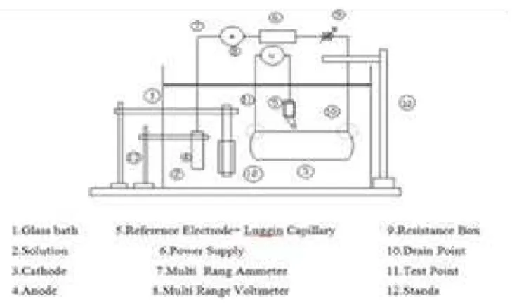
The material used in present study is carbon steel pipe (ASTM API-5L) type as X60 steel because it is widely used in the oil field-Basrah as its price is relatively low, while it provides material properties that are acceptable for such application. It is neither extremely brittle nor ductile due to its low carbon content. It has relatively good tensile strength and is malleable. Its chemical compositions are (C=0.18, P=0.063, Mn=0.52, S=0.039, Si=0.24, Ni=0.10, Cu=0.29, Fe=Remainder).It is placed horizontally at a depth of 5 cm below the corrosive solution and 5 cm above the bottom of the bath. The glass bath was provided with aeration facility with dimension of (10 cm length, 5.2 cm inside diameter , 6 cm outside diameter , 4 mm wall thickness). The auxiliary electrode used was a rod made of graphite with dimension of (20 cm length, and 1cm diameter) . This rod was located horizontally opposite to the working electrode (cathode) at the same level. The graphite anode is one of the most commonly used for impressed current systems, and was chosen for the following reasons [11]: a) Low in cost and it is non consumable, b) Readily available in a variety of size c)Environmentally safe, d) Graphite anode performance is better in seawater than in fresh water. The other materials used are shown in Figure 1.
B) Solution
The solutions used were experimentally prepared in different concentrations of (0 , 0.75 , 1.5 , 2.25 , 3 & 3.5 ) % by adding different weights of (7.5, 15, 22.5, 30 & 35) gm sodium chloride NaCl to 1 litter of distilled water which was supplied by Najibia Power Station Basra with a pH of 6.8 to obtain corrosive solution with different conductivities as (0.025, 17.5, 32.9, 46.6, 60.8, 69.8 ) mS/cm respectively. The NaCl was a commercial type with purity of about 90% which was used as corrosive solution. The cathodic protection system rig was assembled as shown schematically in Figure 1 on the basis of the design criteria proposed by some research workers [ 11, 12, 13].
III.EXPERIMENTALPROCEDURES
A)Sample Preparation and Connections
. The pipe segment (cathode) which was placed in the ICCP system was abraded successively using emery paper to 800 µ in sequences until obtaining a smooth clear surface, then washed with distilled water, and dried with cleaned tissues and finally left to dry by air. A couple of copper wires were connected to the clean pipe surface by braze welding. One of these wires was connected to the negative terminal of DC power supply and the other was connected to the reference electrode which was used to measure the cathodic potential .
Fig. 1 Block Diagram of the installed ICCP .
ﺔﻴ وﺮﺘﻜ ﻻاوﺔﻴﺋﺎﺑﺮﻬﻜ اﺔﺳﺪ ﻬ ﺔﻴﻗاﺮﻌ اﺔ ﺠﻤ ا
Iraq J. Electrical and Electronic Engineering
ﺪ ﺠﻡ
10
دﺪﻌ ا،
2
،
2014
Vol.10 No.2 , 2014
B)Installation and measurements of ICCP
CP system was installed as shown in Figure
1. A Luggin capillary bridge leading to the reference electrode was mounted at the first edge at the center point of the cathode length within ≈ (1-2) mm from the side of the cathode. The opening of the capillary tube located near working electrode (cathode) was equal to (≈ 1mm) in diameter.The working and auxiliary electrodes were 40 cm apart and immersed in the solution at a depth of 5 cm from the top and the bottom respectively. Different weights of NaCl were dissolved in distilled water to 24 liter .The electrolytic solution was stirred by electrical stirrer to obtain a homogenous solution and the temperature of the solution was adjusted and changed in the range (20-45) ̊ C at each run. Another parameter was also aimed to be studied such as aeration from air pumping device which was placed at the center point of the tank between the anode and cathode. The aeration flow rates employed were adjusted at (600, 1500, 1800) l/m to promote various corrosion rates of steel at the specified salt concentrations and at definite temperature. At these conditions the electrode potential was measured with respect to saturated calomel electrode using multi-range voltmeter. The voltage of the D.C power supply was constant at 10 V. To make the protection value of potential at required level the resistance of the circuit was changed until the optimum value was obtained. The current was recorded each 15 min, when the value reached the steady state value i.e. giving the best value of impressed current required for complete cathodic protection , the corresponding voltmeter reading was also recorded. Continuous stirring of the corrosive environment was adapted to accelerate the corrosion process under dynamic condition compared to unstirred static one.
IV.EXPERIMENTALRESULTS &DISCUSSION
A) Effect of Conductivity
Numbers of experiments were carried out to show the effect of solution conductivity on cathodic protection current. It was clear that, whenever the electrical conductivity of a solution increased with salt concentration increment, the impressed current required for protection increased.That is because NaCl is an ionic compound, thus when it is dissolved in water conducts electricity and cause more current flow which leads to more CP current to be required . Figures 2 & 3 show the increment of CP current as conductivity of solution increased in different conditions of temperature with aeration.
Fig.2 CP current vs conductivity at 20 ̊ C
Fig.3 CP current vs conductivity at 45 ̊ C
ﺔﻴ وﺮﺘﻜ ﻻاوﺔﻴﺋﺎﺑﺮﻬﻜ اﺔﺳﺪ ﻬ ﺔﻴﻗاﺮﻌ اﺔ ﺠﻤ ا
Iraq J. Electrical and Electronic Engineering
ﺪ ﺠﻡ
10
دﺪﻌ ا،
2
،
2014
Vol.10 No.2 , 2014
B)Effect of Temperature
From data measurements, it is apparent that the cathodic current increased as the solution temperature increased. The increase of temperature reduces the solubility of dissolved oxygen with subsequent decrease in the rate of oxygen diffusion to the cathode surface then the rate of corrosion was diminished. Figures 4 & 5 show the increment of CP current as temperature increased at different conditions of solution conductivity at different aeration flow rates.
Fig.4 CP current vs temperature at 0.025 (mS/cm) conductivity
Fig.5 CP current vs temperature at 69.8 (mS/cm) conductivity
C) Effect of Aeration Flow Rate
The results showed that there is an increase in the current required as aeration flow rates of the solution increased, but this increment is relatively so small. This is due primarily to the increased availability of reducible species(i.e oxygen) at the structure surface and the resulting increase in the rate of the reduction reaction, i.e. consuming more electrons .When the introduced oxygen to the solution by air pumping and allowed it rapidly to penetrate from the air to the solution (for open systems as in the experiments presented
in this study), and through the solution to the metal surface, besides other reducible species, which increase the current required for protection. After a definite time interval when the solution becomes saturated by oxygen, it reaches a steady state condition and the current did not changed. Figures 2, 3 , 4 , 5 show the increment of CP current as aeration flow rates increased at different solution conductivity and at different temperatures.
V.THEORETICAL RESULTS A) Modeling oF CP System by ANN
For cp application; a neural network model
was chosen as the performance of the chosen model which was tried to maximize the convergence and accuracy of prediction between cathodic protection experimental results and neural network output. The input of neural network is the measured current and the output is the reference electrode (CSE)reading to compare it with set point (reference voltage) according to range of CSE voltage for full protection assuming other parameters are constant .In this study the testing set contains 25 % of total experimental data while the rest were used for training. The artificial neural network was tested by one hidden layer with tansig as a transfer function and purelin function in output layer. Different number of nodes selected (from 1 to 50) in this case the best performance shows at 50 nodes which were obtained after 1000 iterations .Figure 6 shows cathodic protection system modeling by neural network where the actual experimental output(blue)and the ANN output (red) after the learning process and it is clear that the two are almost identical which indicates that a good learning process was achieved. Figure 7 shows the performance of the ANN and Figure 8 shows the correlation coefficient of the network. The network was tested to check if the performance denoted by (MSE) for training sets might diverge. In order to confirm these results, the actual values are compared to those predicted by the neural network for the generalizing patterns.
ﺔﻴ وﺮﺘﻜ ﻻاوﺔﻴﺋﺎﺑﺮﻬﻜ اﺔﺳﺪ ﻬ ﺔﻴﻗاﺮﻌ اﺔ ﺠﻤ ا
Iraq J. Electrical and Electronic Engineering
ﺪ ﺠﻡ
10
دﺪﻌ ا،
2
،
2014
Vol.10 No.2 , 2014
Fig.6 Modeling of ICCP System
Fig.7 Performance of the proposed artificial neural network
B)Control oF CP System
1) Conventional PID controller
In a process control system the controller can be considerate the most important part of the system and can be considered as the “Brain” of process control system .PID control is the most common form of feedback control[12]. The PID term refers to the first letter of the names of the
individual terms that make up the standard three term controller. These are: P for the proportional term; I for the integral term and D for the derivative term in the controller[13].In this work, the PID controller is used to control the voltage applied to pipelines at desired level . The PID controller is used to obtain the error in voltage due to the variation in environments . It is observed that when the parameters ̓ gain are chosen arbitrarily, the response of the system is not satisfactory. The values of the PID gains are obtained manually by using manual tuning (trial and error) method to achieve the desired plant response, the PID gains were found to be (Kp=5, Ki =15, Kd=0.1). This PID controller is set up in Matlab/Simulink environment as shown in Figure 9. When the PID controller is properly tuned the response or plot of the system is obtained as shown in Figure10.
Fig.9 Matlab Simulation of PID Controller for ICCP System.
Fig.8 Correlation coefficient of the proposed artificial neural network
Fig.10 Response of PID Controller for ICCP System.
ﺔﻴ وﺮﺘﻜ ﻻاوﺔﻴﺋﺎﺑﺮﻬﻜ اﺔﺳﺪ ﻬ ﺔﻴﻗاﺮﻌ اﺔ ﺠﻤ ا
Iraq J. Electrical and Electronic Engineering
ﺪ ﺠﻡ
10
دﺪﻌ ا،
2
،
2014
Vol.10 No.2 , 2014
2) Fuzzy Logic Controller . The real world systems are nonlinear.
So it ̓ s accurate modeling is difficult, costly and even not possible in most cases. The conventional control methods such as classical PID solve these problems just about but we need to quick and exact control systems to achieve desired response. It is necessary to know system ̓ s mathematical model or to make some experiments for tuning PID parameters. To overcome these difficulties, various types of controllers were developed lately. One of them is fuzzy control which is a method for system control based on a fuzzy logic. Just as fuzzy logic can be described simply as “computing with Words rather than Numbers”; fuzzy control can be described as “control with sentences rather than equations” [14].The typical architecture of a FLC consists of four principal components namely Fuzzification, Rule-Base, Inference mechanism and Defuzzification as follows[15]:a).Fuzzification(the process of converting a numerical variable (real number or crisp variables) in to a linguistic variable (fuzzy number or fuzzy variable) so that it can be compared to the rules in the rule base.b) Inference Mechanism(uses information about the current inputs and decides the rules that are suitable in the current situation and can form conclusion about system input. c)Rule- Base (a set of If-Then rules which contains a fuzzy logic quantification of the expert’s linguistic description of how to achieve good control. d). Defuzzification(the reverse process of fuzzification is called defuzzification. The linguistic variables are
converted into a numerical variable. The input variables of FLC are the error(e) and
change of error(ce) , the output variable is the current I. Each input is quantized into 3 membership functions : Negative N , Zero Z, Positive P. Also the output variable is quantized into 5 membership functions :Negative big(Nb) , Negative small(Ns) , Zero(Z) , Positive small(Ps) , Positive big(Pb). The basic function of the rule based is to represent the expert knowledge in a form of if-then rule structure. The fuzzy logic can be derived into combination of input (3 × 3) = 9 rules . The rule table of fuzzy logic controller as listed in Table1.
Table (1) Control rules for fuzzy controller
The Matlab simulation of fuzzy controller for ICCP system is shown in Figure 11 and the system response is shown in Figure12.
Fig.11 Matlab Simulation of Fuzzy Controller for ICCP System.
Fig.12 Response of Fuzzy Controller for ICCP System.
This controller is PI-like fuzzy controller. e
σe N Z P
N Nb Ns Z
Z Ns Z Ps
P Z Ps Pb
ﺔﻴ وﺮﺘﻜ ﻻاوﺔﻴﺋﺎﺑﺮﻬﻜ اﺔﺳﺪ ﻬ ﺔﻴﻗاﺮﻌ اﺔ ﺠﻤ ا
Iraq J. Electrical and Electronic Engineering
ﺪ ﺠﻡ
10
دﺪﻌ ا،
2
،
2014
Vol.10 No.2 , 2014
3) Artificial Neural Controller
The control architectures in this part depends on designing ANN identifier which is used as a path to propagate the error between the output of the process and output of the reference model to train and select the optimal values of the trainable parameters of the neural network control. The inputs and outputs data which was obtained from the PID controller was used as training dataset to train the parameters of neural controller (weights and biases) using the Levenberg Marquardt Training Algorithm. Figure 13 explains the training phase of the ANN controller.
Fig.13 Training Phase of ANN controller
The Levenberg-Marquardt training algorithm had been used to obtain the optimal values of the trainable parameters of ANN controller. The ANN controller had three inputs: error, derivative of the error and integral of the error, where the error is the difference between the reference input and output of the controlled system and one output (control signal output). In the training phase, the trainable parameters were randomly initialized. The structure of ANN controller had
been selected as follows: (i) the numbers of the neurons in the hidden layer were selected as 150; (ii) the activation functions of the hidden layer were selected as hyperbolic tangent sigmoid transfer function (tansig); (iii) the activation functions of the output layer were selected as a linear transfer function (purelin); (iv) the training algorithm had been selected as Levenberg Marquardt algorithm (train LM)and (v) the number of the iteration had been selected as 5000. After the last iteration, the outputs of the neural controllers track the outputs of the PID controller. The Matlab simulation of ANN controller for ICCP system is shown in Figure 14. and the system response is shown in Figure 15.
Fig.14 Response of ANN Controller for ICCP System.
Fig.15 Response of ANN Controller of ICCP System.
The time required for each method to track the reference voltage is different as shown in Figures 16& 17.
ﺔﻴ وﺮﺘﻜ ﻻاوﺔﻴﺋﺎﺑﺮﻬﻜ اﺔﺳﺪ ﻬ ﺔﻴﻗاﺮﻌ اﺔ ﺠﻤ ا
Iraq J. Electrical and Electronic Engineering
ﺪ ﺠﻡ
10
دﺪﻌ ا،
2
،
2014
Vol.10 No.2 , 2014
Fig.16 Time Required for Fuzzy Controller of ICCP System
Fig.17 Time Required for Fuzzy Controller of ICCPSystem
PID controller needed time more than fuzzy controller to track reference voltage. As shown in those two Figures PID controller in region (1) took 3.5 sec, but fuzzy controller in the same region took 0.6 sec. So fuzzy controller was faster than PID controller. While ANN controller did not need any time because it was identical to reference voltage .So ANN controller was the best one.
CONCLUSION
1.The values of (Iprot) increased as the conductivity of the solution increased by increasing NaCl content, also increased sharply with increasing the temperature of the solution 2.The values of (Iprot) increased slightly as aeration flow rates increased comparing with the effect of the other investigated parameters, but when the solution became saturated by oxygen, it reached a steady state condition and the current did not changed significantly.
.
3.The sequence effects of the studied parameters on the cathodic protection current can be arranged in the following order:
Temperature>concentration > aeration factor 4.The artificial neural network gave accurate results and was more flexible in terms that it could adapt itself with the change of the
environment variables. 5.It was observed that conventional PID controller can be applied to control ICCP it is a good solution, quite easy to use and create. But, it required very fine tuning of its parameters based on desired reference voltage which cannot cope up with system’s physical parameter variations
like temperature. . 6.It was observed in the present study from
Matlab/Simulink simulation that the fuzzy controller had a good response better and high performance in tracking the reference voltage compared to PID controller . But, the problem with Fuzzy controlling was the tuning of fuzzy inference which was very tedious and required
comprehensive knowledge of the system. .
7.Artificial neural controller was also designed. The results illustrated that the output response of the controlled system had been sharply improved and became fit to reference voltage. . 8.It was found ANN controller had capability of minimizing the control objectives and gave an excellent response better than the two previous controllers. So by proper design PID and Fuzzy controllers can be replaced by ANN controller to control the structure ̍ voltage of ICCP system
REFERENCES
[1] Navfac mo-307;by Hamm. E. R., "Corrosion Control", Naval Facilities Engineering Command, Virginia, SN 0525- LP-542-3100, September, 1992.
[2] Donald M. Waters, P.E., " Demy Stifying Cathodic Protection", Steel Plate FabricatorsAssociation,2005.
[3] Samuel A.Bradford , Ph.D., p.Eng.,
"Corrosion Control" , ISBN 1-894038-58-4 , 2001.
ﺔﻴ وﺮﺘﻜ ﻻاوﺔﻴﺋﺎﺑﺮﻬﻜ اﺔﺳﺪ ﻬ ﺔﻴﻗاﺮﻌ اﺔ ﺠﻤ ا
Iraq J. Electrical and Electronic Engineering
ﺪ ﺠﻡ
10
دﺪﻌ ا،
2
،
2014
Vol.10 No.2 , 2014
[4] C.H. Achebe, Member, IAENG, U.C. Nneke, and O.E. Anisiji , " Analysis of Oil Pipeline Failures in the Oil and Gas Industries in the Niger Delta Area of Nigeria", ISBN 978-988-19251-9-0,2012.
[5] Vishal V. Ghai ," Knowledge Based Approach Using Neural Networks For Predicting Corrosion Rate", Master Thesis , Collage of Engineering and Technology of Ohio University, 2006..
[6] Arthur K. Dunlop, James E. Donham, "ASM Handbook; Corrosion: of Petroleum Production Operation &Corrosion of Pipelines" , Volume 13, AS International, ISBN0-87170-007-7,1992.
[7] Hongchen. F.: NACE CP Instructor,
"Corrosion Control of Underground Pipelines",CorrStop,December,2003.
[8] D. A. Bayliss and D. H. Deacon, "Steelwork Corrosion Control", ISBN 0-203- 30114-5,2002.
[9] API Recommended Practice 1632, "Cathodic Protection of Underground Petroleum Storage Tanks and Piping Systems ", American Petroleum Institute , third edition MAY,1996.
[10]Peabody A.W., "Peabody`s Control of Pipeline Corrosion", second edition, NACE International, ISBN 1-57590-092-0, 2001. .
[11]Mansi. R., " Cathodic protection of impressed current method for carbon steel in 3.5% NaCl solution", MSc. thesis, University of Technology, Chemical Engineering, 2007.. [12]Farhan.SH. Jibrail , Mahrana .R ,"PID
Control of Line Followers" ,National Institute of Technology, Rourkela ,2013.
[13]Abdulshaheed. A.Aldair," Neuro fuzzy Controller Based Full Vehicle NonlinearActive Suspension Systems", Ph.D Thesis ,University of Sussex ,UK ,2012.
[14]MageshwariL.Uma , Loganathan P.S. ," Fuzzy Logic based Position Control System for Tracking Application", IJREAT
International Journal of Research in Engineering & Advanced Technology, Volume 1, Issue 6, ISSN: 2320 – 8791,2014. [15]Ravi Kumar, Chelliah Muthusamy, A.Vinaya
Babu," A Study of Intelligent Controllers Application in Distributed Systems", Indian Journal of Computer Science and Engineering (IJCSE), ISSN : 0976-5166 Vol. 2 No. 4 , 2011.
ﺔﻴ وﺮﺘﻜ ﻻاوﺔﻴﺋﺎﺑﺮﻬﻜ اﺔﺳﺪ ﻬ ﺔﻴﻗاﺮﻌ اﺔ ﺠﻤ ا
Iraq J. Electrical and Electronic Engineering
ﺪ ﺠﻡ
10
دﺪﻌ ا،
2
،
2014
Vol.10 No.2 , 2014