Abstract
In this paper, the problem of vibration suppression of a smart composite plate with bonded piezoelectric patches is considered. A higher order plate model is used for finite element modeling of the plate and the PID controller is used to generate control voltage command to the piezo actuators from the piezo sensors data. De-rived formulation and the control algorithm is implemented in a finite element (FE) code and the FE modeling results are verified using available results of previous studies. The effect of control gain on the vibration suppression characteristics is studied. Fur-thermore, since FE modeling reduces the order of the real prob-lem, the problem of un-modeled residual modes on the so-called spillover effect is investigated.
Keywords
Smart plate; finite element method; vibration suppression; piezoe-lectric; spillover.
Consideration of Spillover Effect in Active Vibration Suppression
of a Smart Composite Plate Using Piezoelectric Elements
1 INTRODUCTION
In many practical applications, such as space satellites, it is important to control the shape or sup-press the vibrations of a lightweight flexible structure. Thus the problems of dynamic analysis and vibration attenuation in flexible components of a spacecraft have been the subject of a number of researches (Azimi et al. 2015; Shahravi & Azimi 2015). Owing to direct and inverse piezoelectric effects, piezoelectric materials can produce electrical charges when they are subjected to mechanical loads, and thus can be used as sensors, or inversely produce strains when they are electrically excit-ed, and thus used as actuators. They have been considered as one of the promising candidates to be used for active vibration control of light-weight structures. Considering the properties of piezoelec-tric materials, active vibration control of structural beams, plates and shells using embedded or surface bonded piezoelectric sensors and actuators has been investigated in many researches (Schulz et al. 2013; Vashist & Chhabra 2013; Wang et al. 2001; Wu et al. 2014). Considering the control of
Eman Eshraqi a Morteza Shahravi b Milad Azimi c
a Researcher, Malek Ashtar University of
Technology, Tehran, Iran. [email protected]
b Malek Ashtar University of Technology,
Tehran, Iran. [email protected] c Space Research Institute, Tehran, Iran.
http://dx.doi.org/10.1590/1679-78253089
piezoelectric smart structures, both conventional and modern control methods have been employed by various researchers. A survey on various control algorithms employed for vibration control of smart structures is presented in (Fei et al. 2010). Classical constant gain velocity feedback control (Farhadi & Hosseini-Hashemi 2011; He et al. 2004) and positive position feedback (PPF) (Baillargeon & Vel 2004) is widely employed for actively vibration control of piezoelectric smart beams and plates.
Investigating open literature reveals that in many studies, finite element (FE) modeling has been used to model the dynamic behavior of the structure (Xu & Koko 2004; Chandrashekhara & Agarwal 1993). In FE modeling of a plate using plate elements, the three-dimensional displacement field is reduced to a two-dimensional problem by adopting an appropriate formulation for variation of displacements across the thickness. Equivalent single layer and layer-wise theories are considered in approximating the displacement field of the structure to derive a reduced 2-D model instead of the complex 3-D model (Reddy 1993; Tornabene et al. 2013; Correia & Gomes 2000). A comprehen-sive research on various theories for displacement field modeling of composite structures with piezo-elements is given by (Benjeddou 2000).
A smart structure is a distributed parameter system with infinite degrees of freedom. Usually a reduced order model (ROM) with finite degrees of freedom pertaining to generalized coordinates is employed for design of a controller. A feedback controller based on a reduced model can destabilize the residual modes. In function of sensor position the feedback can excite the un-modeled state of system (control spillover), and the sensor signals are contaminated by the residual modes
(observa-tion spillover) and degrade the active vibra(observa-tion system efficiency (Dong et al. 2014; Jovanović et al.
2014). Some methods for reduction of spillover effects are discussed by (Mei & Mace 2002; Kim & Inman 2001).
This paper uses a higher order plate theory to derive a finite element model for vibration behav-ior of a composite plate with bonded piezoelectric patches. PID control algorithm is then used to investigate the vibration suppression characteristics of the piezo-actuators using gathered data of piezo-sensors. Effects of controller gain and the un-modelled dynamics in the controller design re-sulting in spillover effect is also studied.
2 FINITE ELEMENT MODELING
A sandwich plate of length and width is considered. The plate consists of a core layer of hon-eycomb structure with thickness , which is sandwiched between two upper and lower face sheets of thicknesses and , respectively. The upper and lower face sheets are covered with piezoelectric patches and solar cells. The piezoelectric sensors/actuators have thickness of and the solar cells have a thickness of . A schematic of smart sandwich plate is shown in Fig. 1.
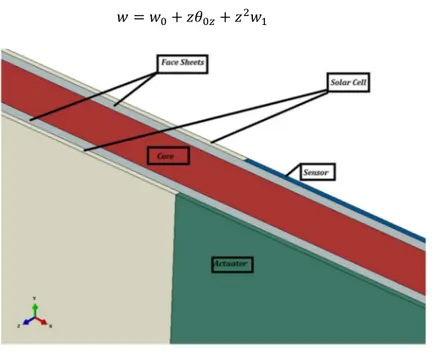
Higher order displacement field as given by (Correia & Gomes 2000), is considered to approxi-mate the three-dimensional problem with a reduced two-dimensional plate model. The displacement field is given by (Correia & Gomes 2000):
(1-a)
(1-c)
Figure 1: Schematic of smart sandwich plate.
Constitutive equations of the piezoelectricity can be written as (Correia & Gomes 2000):
(2-a)
(2.b)
Where {σ} = {σxxσyyσzzσxyσyzσxz}T is the elastic stress vector and {ε} = {εxxεyyεzzγxy γyzγxz}T is
the elastic strain vector. is the matrix of elastic coefficients and is the piezoelectric
coeffi-cients matrix. is the electric displacement vector and is the dielectric matrix. It
is assumed that only the through thickness component of electric field vector is nonzero, thus
, where is given by:
(3)
where is the electric potential across the thickness of the piezoelectric layer. Assuming linear var-iation of the electric potential through the piezo-layers thickness, due to their small thickness
val-ues, the electric field is given by / , where refers to a sensor or actuator piezo patch
layer.
Following the procedure that is given in detail by (Correia & Gomes 2000), and using an eight-noded isoparametric element with eleven displacement degrees of freedom per node and additional one electric potential degree of freedom for each node, the finite element formulation for the dynam-ic governing equation of the smart sandwdynam-ich plate in global form will be given as:
where is the mass matrix and is the structural stiffness matrix, which include
contribu-tions from the core layer, face sheet layers, and solar cells and actuator patches. and
are the elastic-dielectric coupling matrices and is the dielectric stiffness matrix, all of
which contribute to the piezo patch layers. {d, ϕ}T = {u
0, v0, w0, θ0x, θ0y, θ0z, u1, v1, w1, θ1x, θ1y, ϕ}T
is the unknown electro-mechanical nodal degrees of freedom. is the mechanical nodal force
vector and is the nodal electric force vector. Details of elemental mass and stiffness matrices
and the elemental force vectors that are assembled to form the global finite element matrices in Eq. (4) can be found in the work of (Correia & Gomes 2000) and are not repeated here for brevity.
The electric potential vector consists of sensory and actuator components. The electric
volt-age is only externally applied on the actuators. Thus it is possible to write Eq. (4) for sensors and actuators, separately:
(5-a)
(5-b)
(5-c)
Thus the induced electric potential of the sensors can be obtained from the last equation as:
(6)
where sub-indexes A and S refer to actuator part and sensor part of FE coupling stiffness matrices and electric vectors.
2.1 Static Analysis
For the static analysis, it is assumed that the structure is first deformed under the applied mechani-cal load and then the actuator control force is applied based on the sensor voltage which leads to additional deformation of the plate. The total deformation can be obtained from the superposition of two states as follows (Moita et al. 2004):
(7)
where is the total deformation of the plate and denotes deformation due to combination
effects of applied external mechanical load and induced potential in the sensors and denotes
deformation due to actuators voltage. Assuming that first occurs, the induced electric
poten-tials in sensors can be obtained from Eq. (6) by substituting . Substitution of the
result-ing expression for back in to Eq. (5-a) and disregarding inertia terms and actuator voltages,
and putting , can be obtained by solving the following equation (Moita et al. 2004):
(8)
It is assumed that the actuator voltages are the amplified signals of sensors potentials,
i.e. , where is a diagonal matrix of the amplifiers gains.
voltages in the sensors due to , displacement due to actuating voltage can be determined from the solution of the following equation (Moita et al. 2004):
(9)
Total deformation can be obtained by solving Eqs. (8) and (9), and then substitution of the ob-tained results in Eq. (7).
2.2 Dynamic Analysis
Assuming that the converse piezoelectric effect is negligible for sensors, integration of electric dis-placement over the surface of each piezoelectric sensor element determines the output charge of that element as follows (Wang et al. 2001):
,
(10)
where and denote the lower and upper surfaces of the jth element of the ith electroplated
sensor. The total charge of the ith sensor patch is then obtained by summation over all its
constitu-ents elemconstitu-ents (Wang et al. 2001):
Σ (11)
Using the electro-mechanical coupling matrix of the jth element of the ith sensor patch, Eq.
(10) can be re-written as:
(12)
where is the nodal displacement vector of jth element. The total electric charge on the ith
sen-sor can be obtained by assembling the electric charges of all elements in the ith sensor due to Eq.
(11), which gives:
(13)
Piezoelectric sensors are considered to measure the strain rate, thus the output voltage is given by:
(14)
where is the gain of charge amplifier of the ith sensor. Considering Ns total sensors bonded to
the smart sandwich plate, the sensor voltage vector can be expressed as:
… (15)
where is diagonal and is formed by assembling all the corresponding electro-elastic
For the purpose of vibration suppression, the error signal is considered to be the potential of the sensors which should be set to zero by applying appropriate actuating voltages. A PID controller is assumed to produce the required voltage of actuators from the output voltage of the sensors as (Rahman & Alam 2012):
(16)
It is assumed that each sensor patch is accompanied by a corresponding actuator patch with a unique gain. Thus using Eq. (15) it is possible to write:
(17)
where , , and are diagonal matrices of product of PID gains and sensor gains.
Substitu-tion of Eq. (17) into the first relaSubstitu-tion of Eq. (5), the governing equaSubstitu-tions of the moSubstitu-tion of the sys-tem with active damping can be derived as:
(18 )
where is the structural damping with and being the Rayleigh type
damping coefficients. , , and are respectively the active control mass, damping, and
stiffness effects given by:
(19)
(20)
(21)
Eq. (18) can be solved using a direct integration scheme such as the Newmark method (Bathe & Wilson 1976). The PID controller parameters can be obtained using a suitable method such as Ziegler-Nicholes.
3 VERIFICATION STUDIES
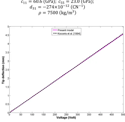
Two numerical examples are considered to assess the accuracy of the developed formulation. In the first example a cantilever bimorph Kynar piezoelectric beam is considered. The upper layer is polar-ized in the direction of applied voltage and the bottom layer has the opposite polarization. The material properties of the Kynar layer are given in (Shakeri et al. 2009). The effect of applied volt-age on the deflection of the free end of the beam is investigated by (Koconis et al. 1994) and are compared with the present study results in Fig. 2. Good agreement is seen between the numerical results of current study with the experimental results of (Koconis et al. 1994).
In the second example a cantilever bimorph piezoelectric beam with the ratio of length to
thickness / is considered. The beam is considered to consist of two PZT layers with opposite
. GPa ; . GPa ; CN
kg/m (22)
Figure 2: Comparison of the results of free end deflection of a cantilevered bimorph Kynar beam under applied voltage.
Exact results for the free end deflection of the beam under two loading conditions including (a)
applied uniformly distributed load of kN/m and (b) applied voltage of V are
given by (Yang & Xiang 2007). The first natural frequency of the beam is also reported in (Lee et al. 2005). These values are compared in table 1 with results of current study derived with FE mod-eling.
Free end deflection (m)
Loading type Exact (Yang & Xiang 2007) Present model
kN/m . .
V . .
First natural frequency (Hz)
(Lee et al. 2005) .
Present model .
Table 1: Comparison of the results of free end deflection and first natural frequency for a bimorph piezoelectric beam.
4 NUMERICAL RESULTS
Verifying the FE model and the corresponding numerical implementation, active control of a smart
at one of its edges and free to vibrate at other edges is considered in this section. The plate consists of an aluminum honeycomb core structure with two face-sheets attached above and below of the core layer which are also made from aluminum. A zig-zag combination of sensor/actuator pairs are located on the face-sheets as shown in Fig. 3. The rest of the surfaces of the sandwich plate is cov-ered with solar cells. Geometric properties and electro-mechanical properties of each layer of the smart plate are given in table 2 and table 3, respectively.
Figure 3: Sandwich plate configuration with zig-zag placement of piezo patches.
Component Thickness (mm) Width (mm) Length (mm)
Core 5 400 400
Face-sheets 1 400 400
Sensors 0.5 100 100
Actuators 0.5 100 100
Solar cells 0.5 100 100
Table 2: Geometric characteristics of the smart sandwich plate.
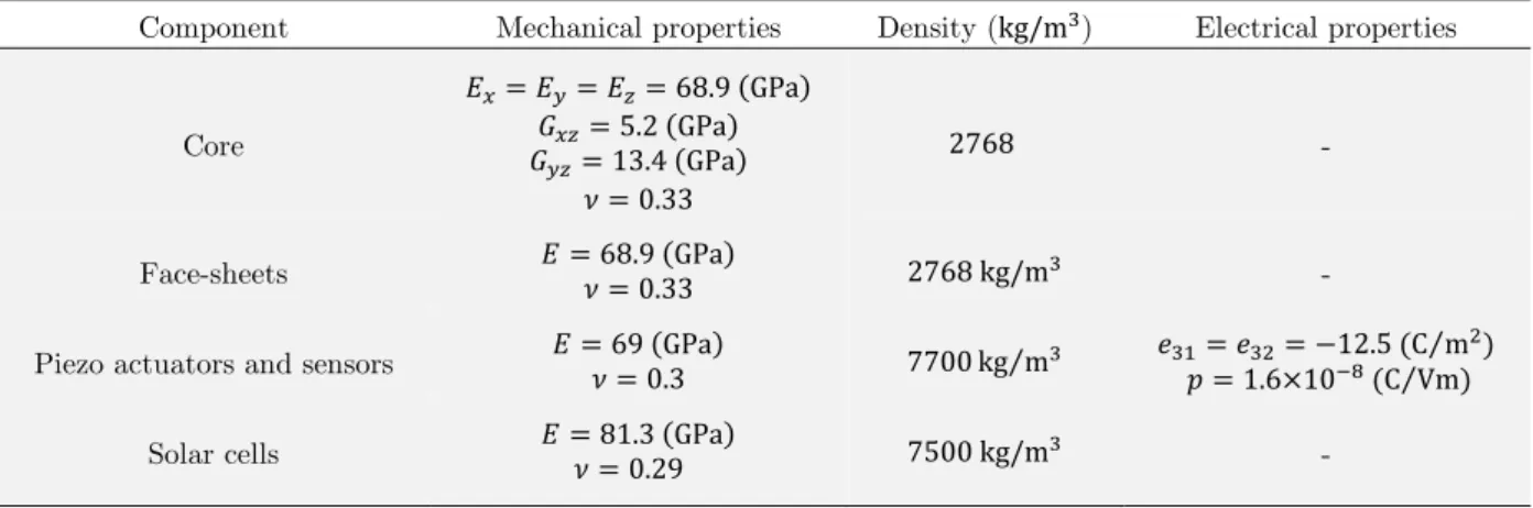
Component Mechanical properties Density (kg/m) Electrical properties
Core
. GPa . GPa
. GPa .
-
Face-sheets . GPa. kg/m -
Piezo actuators and sensors GPa. kg m⁄ . C Vm. C m⁄ ⁄
Solar cells . GPa. kg/m -
Table 3: Electro-mechanical properties of various layers of the smart sandwich plate.
deflec-tion of the line when the plate is subjected to a uniform distributed mechanical load
of / and applied voltage of are shown in Figs. 4 and 5, respectively.
Figure 4: Transverse deflection of the line y mm when the plate is subjected to uniform distributed load.
Figure 5: Transverse deflection of the line y mm when the actuators are subjected to uniform electric voltage.
The first five natural frequencies of the plate obtained from FE analysis based on the theory used in this study is compared with the results obtained from ABAQUS simulation in table 4.
Natural Frequency (Hz)
Mode 1 Mode 2 Mode 3 Mode 4 Mode 5 Present results 38.6 93.1 236.0 302.2 340.0 ABAQUS simulation 38.4 92.3 233.1 298.1 335.2
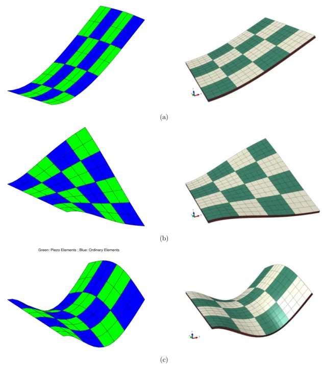
First to third mode-shapes extracted from current FE analysis to those obtained from FE simu-lation in ABAQUS are also compared in Fig 6 (a)-(c).
(a)
(b)
(c)
Figure 6: Sandwich plate mode shapes of free vibration (Left: Present FE analysis, Right: ABAQUS simulation) (a) mode 1, (b) mode 2, and (c) mode 3.
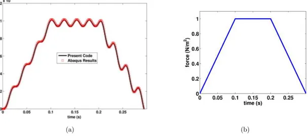
Transient deflection of the mid-node of the plate at the free end ( ,
7 (b) is obtained from FE analysis and simulation in ABAQUS. The results are compared in Fig. 7
(a) for a time period of . .
(a) (b)
Figure 7: Transient deflection of the mid-node at the free end (a) when the plate is subjected to a transient uniform load shown in (b).
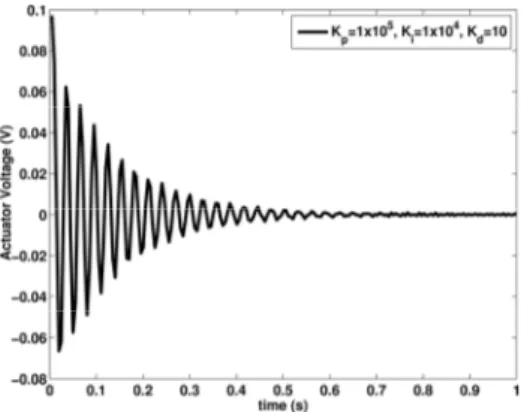
The performance of the PID controller in damping the transverse vibrations of the plate corre-sponding to its first mode of vibration is investigated in Fig. 8. The plate is initially bent by
apply-ing a uniformly distributed load of / , and then removing the load, making the plate to
vibrate at its first natural frequency. The displacement history of the mid-node located at the free
edge of the plate at is used to measure the performance of the PID controller. Structural
damping is neglected. It is observed that the PID controller is able to reduce the vibrations of the plate and make the steady-state response equal to zero. Variation of piezoelectric actuator voltage
for the piezo-patch with its centroid located at / and / , is shown in Fig. 9. The
pie-zoelectric actuator voltage tends to zero as the time increases.
Figure 9: Variation of actuator voltage with time.
5 THE SPILLOVER EFFECT
Flexible smart structures are distributed parameters systems which have infinite degrees of freedom. Active vibration control design usually requires a mathematical model of the structure which is at best a reduced model with finite degrees of freedom. A feedback controller designed based upon a reduced model may stimulate the residual modes (un-modeled dynamics) and make the structure unstable. Due to the sensor location a feedback signal may excite the un-modeled dynamics of the structure or the sensor signals may be contaminated with the residual modes. These are referred to control spillover and observation spillover, respectively.
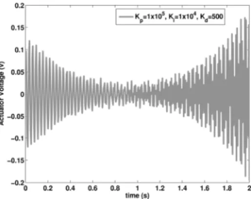
For the PID controller considered in this study, it has been observed that increasing the PID gains have two effects. First, increasing the controller gains results in reduction of the amplitude of vibrations pertaining to the first mode, which is expected since the controller is designed based on vibration suppressions of the first mode. The second effect is that increasing the PID gains results in appearance of vibrations pertaining to higher modes of structural vibration. Since the feedback control leads to excitement of un-modeled states, the performance of the controller is affected by the spillover, when the gains are increased. This can be clearly seen when investigating the response of the smart plate by increasing the derivational gain as shown in Fig. 10. A similar unstability in the voltage of the actuator is also observed as Fig. 11 indicates. As can be seen from this figure, the voltage does not tend to zero as expected and it diverges to higher values with time.
Figure 11: Effect of increasing the derivative gain on the actuator voltage history.
6 CONCLUSIONS
The problem of vibration control of a smart sandwich plate with bonded piezoelectric patches was considered in this study. A higher order plate model was adopted for displacement field variation across the plate thickness. A PID control algorithm was employed to convert sensor signals into actuator voltages. A FE code was written based on the derived formulation incorporating the con-trol algorithm in the transient analysis of the plate.
Verification studies were performed to investigate the accuracy of the developed FE formulation and the written code, and good correspondence was seen to exist between the results of the FE analysis based on higher-order 2-D formulation with the available results in the literature and the results of FE simulations by ABAQUS. Thus, it was shown that the developed model can accurate-ly predict the deflection of the plate under mechanical and electrical loads. The control algorithm was successfully employed to attenuate the flexural vibrations of the smart plate corresponding to its first mode shape. The spillover effect was shown to intensify by increasing the derivative gain of the PID controller. To minimize the spillover effects, it is suggested to optimally place the piezo actuators and sensors on the plate surface.
References
Azimi, M., Shahravi, M., Joubaneh, E. (2015). Dynamic analysis of maneuvering flexible spacecraft appendage using higher order sandwich panel theory, Latin American Journal of Solids and Structures 13: 296–313.
Baillargeon, B. P., Vel, S. S. (2004). Active Vibration Suppression of Sandwich Beams using Piezoelectric Shear Actuators, Advances in Computational & Experimental Engineering & Science 16: 2093–2098.
Bathe, K., Wilson, E. L. (1976). Numerical methods in finite element analysis, Prentice-Hall, Englewood Cliffs, NJ. Benjeddou, A. (2000). Advances in piezoelectric finite element modeling of adaptive structural elements: a survey, Computers and Structures 76: 347–363.
Chandrashekhara, K., Agarwal, A. (1993). Active vibration control of laminated composite plates using piezoelectric devices: a finite element approach, Journal of Intelligent Material Systems and Structures 4: 496–508.
Correia, V., Gomes, M. (2000). Modelling and design of adaptive composite structures, Computer Methods in Ap-plied Mechanics and Engineering 185: 325–346.
Farhadi, S., Hosseini-Hashemi, S. H. (2011). Active vibration suppression of moderately thick rectangular plates, Journal of Vibration and Control, 17: 2040–2049.
Fei, J., Fang, Y., Yan, C. (2010). The Comparative study of vibration control of flexible structure using smart mate-rials, Mathematical Problems in Engineering, 2010: Article ID 768256, 13 pages.
He, X. Q., Ng, T. Y., Sivashanker, S., Liew, K. M. (2001). Active control of FGM plates with integrated piezoelectric sensors and actuators, International Journal of Solids and Structures 38: 1641–1655.
Jovanović, M. M., Simonović, A. M., Zorić, N. D., Lukić, N. S., Stupar, S. N., Petrović, A. S., Wei, L. (2014). Exper-imental investigation of spillover effect in system of active vibration control, FME Transactions 42: 329–334.
Kim, M. H., Inman, D. J., (2001). Reduction of observation spillover in vibration suppression using a sliding mode observer, Journal of Vibration and Control 7: 1087–1105.
Koconis, D. B., Kollår, L. P., Springer, G. S. (1994). Shape control of composite plates and shells with embedded actuators. I. Voltages specified, Journal of Composite Materials 28: 415–458.
Lee, S. Y., Ko, B., Yang, W. (2005). Theoretical modeling, experiments and optimization of piezoelectric multi-morph, Smart Materials and Structures 14: 1343–1352.
Mei, C., Mace, B. R. (2002). Reduction of control spillover in active vibration control of distributed structures using multioptimal schemes, Journal of Sound and Vibration 251: 184–192.
Moita, J. M. S., Correia, I. F., Soares, C. M. M., Soares, C. A. M. (2004). Active control of adaptive laminated structures with bonded piezoelectric sensors and actuators, Computers & Structures, 82: 1349–1358.
Rahman, N., Alam, M. N. (2012). Active vibration control of a piezoelectric beam using PID controller: Experi-mental study. Latin American Journal of Solids and Structures, 9: 657–673.
Reddy, J. N. (1993). An evaluation of equivalent-single-layer and layerwise theories of composite laminates, Compo-site Structures 25: 21–35.
Schulz, S. L., Gomes, H. M., Awruch, A. M. (2013). Optimal discrete piezoelectric patch allocation on composite structures for vibration control based on GA and modal LQR, Computers & Structures 128: 101–115.
Shahravi, M., Azimi, M. (2015). A comparative study for collocated and non-collocated sensor/actuator placement in vibration control of a maneuvering flexible satellite, Proceedings of the Institution of Mechanical Engineers, Part C: Journal of Mechanical Engineering Science 229: 1415–1424.
Shakeri, M., Sadeghi, S. N., Javanbakht, M., Hatamikian, H. (2009). Dynamic analysis of functionally graded plate integrated with two piezoelectric layers, based on a three-dimensional elasticity solution, Proceedings of the Institu-tion of Mechanical Engineers, Part C: Journal of Mechanical Engineering Science 223: 1297–1309.
Tornabene, F., Viola, E., Fantuzzi, N. (2013). General higher-order equivalent single layer theory for free vibrations of doubly-curved laminated composite shells and panels, Composite Structures 104: 94–117.
Vashist, S. K., Chhabra, D. (2014, March). Optimal placement of piezoelectric actuators on plate structures for active vibration control using genetic algorithm, In SPIE Smart Structures and Materials+ Nondestructive Evalua-tion and Health Monitoring (905720-905720), InternaEvalua-tional Society for Optics and Photonics.
Wang, S. Y., Quek, S. T., Ang, K. K. (2001). Vibration control of smart piezoelectric composite plates, Smart mate-rials and Structures 10: 637–644.
Wu, D., Huang, L., Pan, B., Wang, Y., Wu, S. (2014). Experimental study and numerical simulation of active vibra-tion control of a highly flexible beam using piezoelectric intelligent material, Aerospace Science and Technology 37: 10–19.
Xu, S. X., Koko, T. S. (2004). Finite element analysis and design of actively controlled piezoelectric smart structures, Finite Elements in Analysis and Design, 40: 241–262.