Vučković, G. D., et al.: Avoidable and Unavoidable Exergy Destruction and …
THERMAL SCIENCE, Year 2012, Vol. 16, Suppl. 2, pp. S433-S446 S433
AVOIDABLE AND UNAVOIDABLE EXERGY DESTRUCTION AND
EXERGOECONOMIC EVALUATION OF THE THERMAL PROCESSES
IN A REAL INDUSTRIAL PLANT
by
Goran D. VU^KOVI]a*, Mi}a V. VUKI]a,
Mirko M. STOJILJKOVI]a, and Dragan D. VU^KOVI]b a Faculty of Mechanical Engineering, University of Niš, Niš, Serbia
b Faculty of Electronic Engineering, University of Niš, Niš, Serbia
Original scientific paper DOI: 10.2298/TSCI120503181V
Exergy analysis is a universal method for evaluating the rational use of energy. It can be applied to any kind of energy conversion system or chemical process. An exergy analysis identifies the location, the magnitude and the causes of thermo-dynamic inefficiencies and enhances understanding of the energy conversion processes in complex systems. Conventional exergy analyses pinpoint compo-nents and processes with high irreversibility. To overcome the limitations of the conventional analyses and to increase our knowledge about a plant, advanced exergy-based analyses are developed. These analyses provide additional infor-mation about component interactions and reveal the real potential for improve-ment of each component constituting a system, as well as of the overall system. In this paper, a real industrial plant is analyzed using both conventional and ad-vanced exergy analyses, and exergoeconomic evaluation. Some of the exergy de-struction in the plant components is unavoidable and constrained by technologi-cal, physical and economic limitations. Calculations related to the total avoida-ble exergy destruction caused by each component of the plant supplement the outcome of the conventional exergy analysis. Based on the all-reaching analysis, by improving the boiler operation (elimination of approximately 1 MW of avoid-able exergy destruction in the steam boiler) the greatest improvement in the effi-ciency of the overall system can be achieved.
Key words: exergy, exergy destruction, conventional exergetic analysis, advanced exergy analysis, exergoeconomic
Introduction and background
Exergy analysis is a mighty tool for development, assessment and improvement of all existing energy systems. A conventional exergy analysis denotes components and processes into the energy systems that are highly unrecoverable [1]. For complex energy sys-tems, with large number of components, exergy destruction of a certain component depends on its own characteristics, but also on other components inefficiencies. The conventional ex-ergy analysis displays certain limitations which are considerably decreased in an advanced or
––––––––––––––
* Corresponding author; e-mail: [email protected]
po širini i po
detailed exergy analysis [2]. In this point of view, the advanced exergy analysis performs the splitting total exergy destruction into the parts. In the one division, total exergy destruction can be splitting into the part which can be avoided, therefore called ''avoidable'', and into the part which can not be avoided, named ''unavoidable''. In the other division exergy destruction can be splitting into the endogenous and exogenous exergy destruction which are not going to be dealt with in this paper. An advanced exergy analysis has the purpose to supply engineers with more useful information related to energy systems improvement potential.
In their paper Tsatsaronis et al. [3] split exergy destruction into avoidable and un-avoidable parts and demonstrate the advantages of dividing exergy destruction and economic costs into avoidable and unavoidable parts on the example of cogenerative plants. In the paper Morosuk et al. [4] introduced how to calculate the parts of exergy destruction in an advanced exergy analysis. Application of this approach to a simple gas-turbine system reveals the po-tential for improvement and the interactions among the system components. The same authors in the paper [5] presented a detailed exergy analysis of a novel co-generation concept that combined LNG regasification with the generation of power.
The first idea of combining thermodynamics and costs originated from Lotka in 1921 [6]. In 1932, Keenan suggested using the second law of thermodynamics regarding the costs [7]. Even though the work was not about exergy costs, exergy (at that point “availabil i-ty”) has been used to separate costs of electricity and steam produced in cogeneration plants. Keenan showed that the ''availability'' is more convenient property to base evaluation of elec-tricity and steam than energy.
Tribus et al. was firstly expressed the interest for formulating connections between the efficiency and costs [8]. They suggested an idea about the costs of exergy and its uses in engineering economy, introducing the term “Thermoeconomics” in 1956 [9]. The essence of Evans-Tribus approach lies in the management of money, fuel costs, work costs, and amor-tized capital costs related to plants by connecting the usefulness of each step with its exergy. El-Sayed and Evans published in 1970 a crucial paper [10], which proposes the mathematical explanation/foundation for the optimization of heat systems. Many years later, Frangopoulos, in 1983, and Von Spasovsky, in 1986, applied and formalized Evans and El-Sayed’s optim i-zation method, in their Ph. D. theses.
Methodology
Energy and conventional exergy analysis
Since the engineering analyses, energy systems are very often idealized as being at steady-state, meaning that all the properties are not changed in time. For a control volume at steady-state, the identity of the matter within the control volume changes continuously, but the total amount of mass remains constant [17]. The control volume energy balance rate at the steady state for the k-th component, without kinetic and potential energy, is [18]:
cv cv
0 k k i k k e
i e
Q W m h m h (1)
The conventional exergy analysis, presented in this paper, can be classified as exer-gy flow method or exerexer-gy balance method [19, 20]. According to this method the control vo-lume exergy balance rate at the steady state for the k-th component of the energy system can be expressed as [18]:
, , cv , , D,
0 q k j k i k e k
j i e
E W E E E (2)
Fuel-product concept and splitting exergy destruction
Definitions of exergy efficiency and exergoeconomic analysis rely on the so-called concept of ''Fuel-Product'' [13]. The product is defined in accordance with the aim of purchase and the use of the component. The term fuel stands for the primary energy, raw materials, semi-products and others, which is needed for making product. In exergy analysis the fuel and the product are expressed by means of exergy dimensions. The value of exergy destruction for tne overall energy system, can be calculated using the ''Fuel-Product'' concept from the exergy balance for the total energy system:
F,tot P,tot L,tot D,tot
E
E
E
E
(3)Using the same concept for component level, exergy balans can be expressed as:
F,k P,k L,k D,k
E
E
E
E
(4)The loss of exergy is characterized as irreversibility as a result of the interaction be-tween the system and the surrounding environment. These irreversibility values may be de-termined by the transfer of matter in the surroundings or by transferring the heat energy or work in the surrounding. Often the exergy loss presents a small part of thermodynamic ineffi-ciencies, while the most part generates unrecoverable values within the system. If the bounda-ries of a system or a component are set where the temperature is equal to the referent envi-ronment temperature, all the thermodynamic inefficiencies are assigned to the exergy destruc-tion, while the exergy loss is equal to zero, ĖL,k = 0.
energy system have its fuel and products, but the whole system also has its fuel (the resource) and its products (finished products).
The total exergy destruction calculated from the exergy balance of the component can be splitting into an avoidable and unavoidable part [4, 21]:
AV UN
D,k D,k D,k
E E E (5)
The unavoidable part of exergy destruction of the component presents a part which cannot be eliminated, even if the best available technologies are used. In order to determine the unavoidable part of exergy destruction in a system component, it is required to consider each component separately from the others, as if it was removed from the system [22]. At the same time, the premise is that the component works in unavoidable conditions – with high ef-ficiency and minimal losses [1]. Under these conditions, the specific unavoidable exergy de-struction is defined as the ratio between the exergy dede-struction of the component and the ex-ergy of its product (ĖD,k/ĖP,k)UN. The specific unavoidable exergy destruction should be
mul-tiplied with the exergy of product of the component in real operating conditions [23]:
UN D, UN
D, P,
P,
k
k k
k
E
E E
E (6)
The calculated value using the equitation (6) represent a part of exergy destruction of the component which cannot be avoided in the observed energy system. When calculating the un-avoidable part of exergy destruction, the decision maker has to introduce certain presumptions re-lated mainly to the work conditions of the components, that are, to some extent, arbitrary and rely on the subjective comprehention and predictions related to the future enhancements.
The avoidable part of exergy destruction represents the difference between the total exergy destruction of the component and the part which cannot be avoided, eq. (5). Thus, the avoidable part of exergy destruction is the objective potential for improving the efficiency of the component in an energy system.
Real and unavoidable operation conditions and exergy efficiency
Making a distinction between the avoidable and unavoidable part of exergy destruc-tion is possible only after defining the total value of exergy destrucdestruc-tion for the component under considerations. Calculating the total value of exergy destruction is the first step in the conven-tional exergy analysis or in observes the energy system in realistic conditions. The real operation conditions include real in-going data and actual thermodynamic efficiency for all components in energy system under considerations. Using the data obtained from the conventional exergy analysis application, one cannot get insight into improvement potential of the entire energy sys-tem or certain components. Moreover, contributions of other components are not recognized.
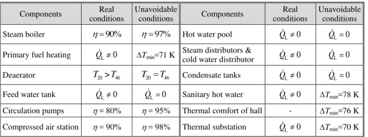
theoretical knowledge, following the current progress in science. In general, the unavoidable operation conditions are the better than the real working ones, but they are not equivalent to the ideal (theoretical) operation conditions. Table 1 summarizes assumptions of real and un-avoidable operation conditions based on approach published in [22]. In the heat exchanger, the minimum temperature differences in unavoidable conditions have been estimated in ac-cordance the temperature levels of steam and water in the referent plant. Heat losses to the environment for devices are estimated 2% of heat capacity.
Table 1. Assumptions of real and unavoidable operation conditions
The exergy efficiency is one of the most important criterions for evaluation of the system or components from the thermodynamic point of view. Exergy efficiency in a ''Fuel-Product'' concept was defined by Tsatsaronis in 1993 at the component level as a ratio be-tween the exergy values of the product and the fuel:
P,
F,
k k
k
E
E (7)
Exergy efficiency is frequently also given in the next form:
1
P, D,
P, D, P,
1
k k
k
k k k
E E
E E E (8)
Exergy efficiency shows what percentage of fuel exergy can be found in a product exergy of a system, plant or component under consideration. The difference between 100% and the actual value of exergy efficiency equals the percentage of fuel exergy which has been lost in a system either as exergy destruction or exergy loss [18].
When represented with a mathematical expression (8), exergy efficiency is suitable for determining the maximum exergy efficiency in a component [23]:
1 UN D, max
P,
1 k
k
k
E
E (9)
The component will have maximum exergy efficiency when it working with minim-al vminim-alue of specific unavoidable exergy destruction, eq. (9).
Components Real conditions
Unavoidable
conditions Components
Real conditions
Unavoidable conditions
Steam boiler 90% 97% Hot water pool QL 0 QL 0
Primary fuel heating QL 0 Tmin=71 K
Steam distributors
cold water distributor QL 0 QL 0
Deaerator T20>T46 T20 T46 Condensate tanks QL 0 QL 0
Feed water tank QL 0 QL 0 Sanitary hot water QL 0 Tmin=78 K
Circulation pumps = 80% = 95% Thermal comfort of hall - Tmin=76 K
A useful variable for comparison of dissimilar components is the exergy destruction ratio, defined at the component level as:
D, D,
F,tot
k k
E y
E (10)
The exergy destruction ratio is a measure of the contribution of the exergy destruc-tion within the k-th component to the reduction of the overall exergy efficiency [1].
Exergoeconomic analysis
Exergoeconomic costs basically stand for the monetary costs of stream of matter and energy flows. The functions of exergoeconomic costs for: incoming and outgoing stream of matter, exergy connected with the work transfer and exergy related to the heat transfer may be represented as products of average exergoeconomic costs per unit of exergy and a suitable value of exergy and work in the following forms [18], respectively: Ci c Ei i c m ei( i i),
( ),
e e e e e e
C c E c m e Cw c Ww , and Cq c Eq q c Qq (1 T T0/ )s .
In the “Fuel-Product” concept, for an energy system in a steady state, the cost of fi-nished products equals the sum of the resource costs, costs regarding capital investment, oper-ation and maintenance, and it can be presented in the following mathematical expression:
CI OM
P,tot F,tot tot tot F,tot tot
C C Z Z C Z (11)
Equation (11) represents exergoeconomic balances of the overall energy system. The same form of eq. (11) is valid for the component level, also.
Defining exergoeconomic costs implies determining exergoeconomic balance for every component individually within a system. Exergoeconomic balance for every component shows that the sum of exergoeconomic cost rates associated with all exiting exergy streams equals the sum of exergoeconomic cost rates of all entering exergy streams plus a value of costs regarding capital investment and operating and maintenance. For a component receiving a heat transfer and generating power, the exergoeconomic balance can be expressed as [18]:
, , , ,
e k w k q k i k k
e i
C C C C Z (12)
If it is a case of those components which exploit energy (such as compressors or pumps), the second term of eq. (12) moves to the right side. Furthermore, the first term on the right side of eq. (12) moves to the left side in the case of a heat emitting component. In gener-al, exergoeconomic balance is always given with the terms being positive. By using mathe-matical expressions for, Ċi, Ċe,Ċw, Ċq, equation (12) becomes:
, , ,
e e k w k k q k q k i i k k
e i
c E c W c E c E Z (13)
have any outgoing flows that are not qualified as the loss flows, or a branching there of, addi-tional equations for each component have to be added. The number of added equations is equal to the number of outgoing flows minus one.
The relative cost difference for the energy system components is defined as:
P, F,
F,
k k
k
k
c c
r
c (14)
This variable stands for the relative increase in costs per exergy unit between the fuel and product of the component in question. The relative increase in costs is very useful when both calculating and optimizing the system component.
Process description
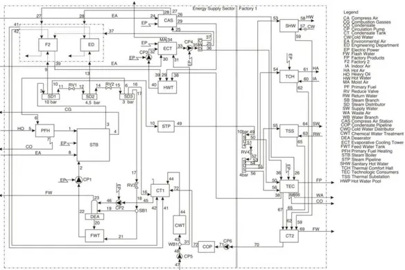
The energy system in a representative factory, fig. 1, consists of four parts: Energy supply sector (EN), Factory 1 (F1), Factory 2 (F2), and Engineering department (ED).
Energy supply sector is a part of the factory complex where chemical and thermal treatment of water is carried out, and superheated steam for their own use and supply of all other consumers is produced. Also, in this section, compressed air and cooling water for the whole factory complex are prepared. The boiler produces superheated steam at the pressure of 10 bar, which is then distributed to factories 1 and 2, and partly reduced at lower pressures in accordance with the needs of consumers. In this paper, it is assumed that the fuel used is heavy oil. Compressed air at pressure of 7 bar is prepared in the compressed air station where electricity is used to drive the compressors. Consumers of compressed air are Factory 1, Fac-tory 2, and Engineering department. Cooling water for both factories is prepared in the eva-porative cooling tower. A spray jet of cooling water, transported from the pool of hot water, spreads over the tube bundle of evaporative heat exchanger and collects into the reservoir. Forced air flow is provided with the centrifugal ventilator, while water drops removal within the air flow is prevented with the droplet eliminator. The cooled water transported with pump 4 to consumers in factories 1 and 2, and compressed air station.
the drain ditch. The production technology requires the use of compressed air, which is re-jected to environment after use.
Figure 1. Flow diagram of the representative industrial plant
Also, the cooling water in the factory is used for technological needs. During the production process, temperature of cooling water increases. All consumers of the electricity in the factory, as well as technological consumers are supplied with the electricity from a sepa-rate transformer station. Factory 2 is supplied with steam at pressure of 10 bar. Condensate from Factory 2 returns to the condensate tank 1. Engineering department requires steam at 4 bar. Condensate from the Engineering department is returned in the full amount.
In this paper, Factory 1 is discussed in detail. The effects of Factory 2 and the part that deals with Engineering department are considered on the basis of real values of super-heated steam that they use. The representative system of the considered rubber factory was mathematically modeled with 30 components and 72 streams.
Results and discussion
Each segment of the system shown in fig. 1 was separately analyzed and for each component mass, energy and exergy balances were defined. The results of the thermodynamic and exergoeconomic analysis for selected steams are presented in tab. 2. Input data for the calculation were pressures and temperatures in different points of the flows of streams ob-tained from the existing process of the referent plant. Official data on lower heating values for the fuel were used. The cost of air provided was considered to be zero. The highest values of the cost rate Ci, were reached in the representative industrial plant in streams that had high
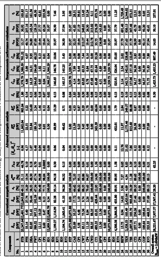
For solving the defined mathematical model, a specialized software package called Engineering Equation Solver [24] was used. The results of the conventional and advanced ex-ergetic analysis and exergoeconomic analysis at the component level are presented in tab. 3. The rate Zk for the steam boiler, circulation pumps and compressed air station was calculated
include the estimated investment cost for implementing energy efficiency measures and real annual operating and maintenance cost, and for the other components by dividing the real an-nual operating and maintenance cost with the 4000 hours of system operation per year.
Having in mind that the reduce valves typically serve other elements, the reduce valve and the component it serve should be considered together [18]. In the manner of con-ventional exergy analysis, exergy of fuel and product, exergy destruction, exergy efficiency and exergy destruction ratio for selected components are presented in this paper. Values of unavoidable and avoidable exergy destruction are also presented for selected components in the advanced exergy analysis in this paper. Values of operation and maintenance cost, goeconomc cost and relative cost difference for selected components are presented in exer-goeconomic evaluation.
Values for cooling tower were not calculated, because thay have no meaningful ef-fect on the product, and thus no meaningful exergy efficiency, for a heat exchanger that al-lows heat transfer across the temperature of environment [18]. The impact of technological consumers on the other system components is taken through the flow rate values of process fluids, which correspond to the real plant depending on the amount of finished products.
The exergy efficiency of a total plant indicates that some potential exists for the im-provement of the overall efficiency and reduction of costs. Exergy losses are mainly asso-ciated with the exhaust gases as well as the exergy transfer to the environment. From the total exergy losses, the loss of exhaust gas is 82.54% or 2,225.75 kW. All exergy losses account together for 9.82% or 2,696.69 kW of the fuel exergy supplied to the overall plant. More than 48% of the fuel exergy is destroyed within the plant components. The exergy destruction ratio provides information about the performance of each component and enables the comparison of dissimilar components. Values for exergy destruction ratio indicate that the boiler has most impact on reducing exergy efficiency of the overall system.
The steam boiler has a big potential for increasing the efficiency, forasmuch it hav-ing the highest value of exergy destruction ratio (46.78%), but very low value for exergy effi-ciency (49.12%).
When evaluating any energy system, we mainly focus on its avoidable exergy de-struction, because it represents the potential for improvement. Advanced exergy analysis gives us information that 7.66% (983.84 kW) of exergy destruction for steam boiler is avoid-able. Circulation pumps have the greatest potential for improvement (in %) using the best avoidable technology (more than 70%), but the absolute values are very small. Compressed air station has bigger values for improvement, 4.44 kW or 24.44%.
Exergy destruction in a deaerator is mainly caused by differences in temperature and pressure of the water streams being mixed. These thermodynamic inefficiencies can be com-pletely avoided when the feed water and the steam have the same temperature and pressure and the plant component is considered in isolation. Having in mind that the capital invest-ments of all existing components represent sunk costs in the real plant, capital investment is ignored in this paper for exergoeconomic performance evaluation.
Table 2. Calculated variables for selected streams
Str. mj pj tj hj sj
PH
j
e CH
j
e
E
j Cj cj[kgs1] [bar] [ C] [kJkg1] [kJkg1K1][kJkg1] [kJkg1] [kW] [€h1] [€GJ1]
Table 2. (Continuation)
Components such as CT1, SHW, TKH, and TSS have very high values of the rela-tive cost difference, but it is noticeable that their values of exergy of fuel and exergy destruc-tion are many times greater than the exergy of product. Therefore, the general suggesdestruc-tion is to reduce the exergy of flows 16, 53, 54, and 55 with the aim of increasing the efficiency of the overall system and reducing the consumption of heavy oil.
Str. mj pj tj hj sj
PH
j
e CH
j
e
E
j Cj cj[kgs1] [bar] [ C] [kJkg1] [kJkg1K1] [kJkg1] [kJkg1]
Ta
b
le 3
.
Re
sul
ts o
f
th
e
co
n
v
en
ti
o
n
a
l
a
n
d
a
d
v
a
n
ce
d
e
x
er
g
y
a
n
a
ly
sis
a
n
d
e
x
er
g
o
ec
o
n
o
m
ic ev
a
lu
a
tio
n
a
t
th
e
co
m
p
o
n
en
t
le
v
Conclusions
The results of the conventional exergy analysis are strongly supplemented by the ad-vanced exergy analysis. Irreversibilities identified in the conventional exergy analysis are split, ac-cording to their origins, in the advanced exergy analysis. Only the part of the irreversibilities that can be avoided should be considered for the improvement of a plant with interacting processes.
In this paper, an industrial plant was analyzed using both conventional and advanced exergy analysis, and exergeconomic performance evaluation. The highest exergy destruction is caused by the steam boiler. More than 97% of the total exergy destruction of the overall system comes from the boiler. Moreover 92.34% of the total exergy destruction in steam boi-ler cannot be avoided. Similar to the results of the conventional analysis, the advanced analy-sis ranks the improvement priority of the steam boiler first, followed by the thermal comfort of the hall and the thermal substation.
The splitting exergy destruction into endogenous and exogenous parts, combined splitting, and consideration the increase in pressure and temperature of the generated steam, in order to have a cogeneration plant, increasing the factory performances we are investigation in the next step in this study.
Nomenclature
Ċ – exergoeconomic cost rate, [€s1]
c – cost per unit of exergy, [€J1]
Ė – exergy flow rate, [kW]
e – specific exergy, [kJkg 1]
h – specific entalphy, [kJkg1] m – mass flow rate, [kgs1]
Q – heat transfer rate, [kW]
r – relative cost difference, [–]
s – specific entrophy, [kJkg1K1]
T – temperature, [K]
t – temperature, [C] W – work rate, [kW]
yD – exergy destruction ratio Z – non-exergy cost rate, [€s1]
Greek symbols
– difference – exergy efficiency – thermal efficiency
Subscripts
cv – control volume D – destruction e – outlet stream F – fuel
j – stream of matter k – system component L – loss
min – minimal P – product q – heat transfer tot – overall system w – work
Superscripts
AV – avoidable CH – chemical max– maximal PH – physical UN – unavoidable
References
[1] Petrakopoulou, F., et al., Conventional and Advanced Exergetic Analyses Applied to a Combined Cycle Power Plant, Energy, 41 (2012), 1, pp. 146-152
[2] Kelly, S., Tsatsaronis, G., Morosuk, T., Advanced Exergetic Analysis: Approaches for Splitting the Ex-ergy Destruction into Endogenous and Exogenous Parts, Energy, 34 (2009), 3, pp. 384-391
[3] Tsatsaronis, G., Park, H., On Avoidable and Unavoidable Exergy Destructions and Investment Costs in Thermal Systems, Energy Conversion and Management, 43 (2002), 9-12, pp. 1259-1270
[5] Tsatsaronis, G., Morosuk, T., Advanced Exergetic Analysis of a Novel System for Generating Electrici-ty and Vaporizing Liquefied Natural Gas, Energy, 35 (2010), 2, pp. 820-829
[6] Sciubba, E., Wall, G., A Brief Commented History of Exergy from the Beginnings to 2004, Internation-al JournInternation-al of Thermodynamics, 10 (2007), 1, pp. 1-26
[7] Keenan, J. H, A Steam Chart for Second Law Analysis, Mechanical engineering, 54 (1932), 1, pp. 195-204
[8] Abusoglu, A., Kaganlu, M., Exergoeconomic Analysis and Optimization of Combined Heat and Power Production: A Review, Renewable & Sustainable Energy Reviews, 13 (2009), 9, pp. 2295-2308 [9] Tribus, M., et al: Thermodynamic and Economic Considerations in the Preparation of Fresh Water from
Sea Water, First Draft, ULCA Report No. 56-16, University of California, Los Angeles, Cal., USA, 1956 [10] El-Sayed, M. Y., Evans, R. B., Thermoeconomics and the Design of Heat Systems, Journal of
Engi-neering for Power, 92 (1970), 1, pp. 27-35
[11] Kotas, T. J., The Exergy Method of Thermal Plant Analysis, Butterworths, London, UK, 1985
[12] Tsatsaronis, G., Combination of Exergetic and Economic Analysis in Energy-Conversion Processes, Proceedings, European Congress, Energy Economics and Management in Industry, Algarve, Portugal, 1984, Pergamon Press, Oxford, England, Vol. 1, pp. 151-157
[13] Tsatsaronis, G., Winhold, M., Exergoeconomic Analysis and Optimization of Energy Conversion Plants. Part I: A New General Methodology; Part II: Analysis of a Coal – Fired Steam Power Plant, Energy, 10 (1985), 1, pp. 69-94
[14] Rosen, A. M., Exergy and Economics: Is Exergy Profitable?, Exergy, 2 (2002), 4, pp. 218-220
[15] Rivero, R., Garcia, M., Urquiza, J., Simulation, Exergy Analysis and Application of Diabatic Distillation to Tertiary Amyl Methyl Ether Production Unit of a Crude Oil Refinery, Energy, 29 (2004), 3, pp. 467-489
[16] Valero, A., Cuadra, T. C., Application of Thermoeconomic to Operation Diagnosis of Energy Plants, in Exergy, Energy System Analysis and Optimization, Vol. 2 (Ed. C. A. Frangopoulos), EOLSS, Oxford, UK, 2009, pp. 146-161
[17] Moran, M., Shapiro, H., Fundamentals of Engineering Thermodynamics, John Wiley & Sons Inc., New York, USA, 2006
[18] Bejan, A., Tsatsaronis, G., Moran, M., Thermal Design and Optimization, John Wiley & Sons Inc., New York, USA, 1996
[19] Szargut, J., Morris, D., Steward, F., Exergy Analysis of Thermal, Chemical, and Metallurgical Processes, Hemisphere Publishing Corporation, New York, USA, 1988
[20] Wall, G., Conditions and Tools in the Design of Energy Conversion and Management System of a Sus-tainable Society, Energy Conversion and Management, 43 (2002), 9-12, pp. 1235-1248
[21] Morosuk, T., Tsatsaronis, G., How to Calculate the Parts of Exergy Destruction in an Advanced Exeget-ic Analysis, Proceedings, 21st ECOS Conference, Cracow, Poland, 2008, Vol. 1, pp. 185-194
[22] Cziesla, F., Tsatsaronis, G., Gao, Z., Avoidable Thermodynamic Inefficiencies and Costs in an External-ly Fired Combined Cycle Power Plant, Energy, 31 (2006), 10-11, pp. 1472-1489
[23] Kelly, S., Energy Systems Improvement based on Endogenous and Exogenous Exergy Destruction, Ph. D. thesis, Technische Universität Berlin, Berlin, 2008
[24] ***, Engineering Equation Solver, http://www.fchart.com
![Table 2. Calculated variables for selected streams Str. m j p j t j h j s j e PHj e CHj E j C j c j [kgs 1 ] [bar] [ C] [kJkg 1 ] [kJkg 1 K 1 ] [kJkg 1 ] [kJkg 1 ] [kW] [€h 1 ] [€GJ 1 ] 1 0.63 1.01 80.0 -2,256.00 2.21 8.60 43,707.00 27,4](https://thumb-eu.123doks.com/thumbv2/123dok_br/17247774.245506/10.722.73.656.111.945/table-calculated-variables-selected-streams-phj-kjkg-kjkg.webp)