AN EXPERIMENTAL INVESTIGATION OF PERFORMANCE
OF A DOUBLE PASS SOLAR AIR HEATER WITH
THERMAL STORAGE MEDIUM
by
Hafiz Muhammad ALI*, Arslan Iqbal BHATTI, and Muzaffar ALI
Department of Mechanical Engineering, University of Engineering and Technology, Taxila, Pakistan
Original scientific paper DOI:10.2298/TSCI140824140A
The performance of a double pass solar air heater was experimentally investigat-ed using four different configurations. First configuration containinvestigat-ed only absorb-er plate whabsorb-ereas coppabsorb-er tubes filled with thabsorb-ermal storage medium (paraffin wax) were added on the absorber plate in the second configuration. Aluminum and steel rods as thermal enhancer were inserted in the middle of paraffin wax of each tube for configurations three and four, respectively. Second configuration provided useful heat for about 1.5 hours after the sunset compared to first con-figuration. Configurations three and four provided useful heat for about 2 hours after the sunset. The maximum efficiency of about 96% was achieved using con-figuration three (i. e. using aluminum rods in the middle of copper tubes filled with paraffin wax).
Key words: paraffin wax, aluminum rods, stainless steel rods, thermal storage
medium
Introduction
Krishnananth and Murugavel [1] investigated experimentally the performance of double pass solar air heater (SAH). They used paraffin wax encapsulated in six aluminum pipes and studied the behavior of solar heater for four different configurations. In configura-tion 1, no thermal storage medium (TSM) was used. In configuraconfigura-tion 2 and 3, the Al pipes filled with TSM were placed above and below the absorber plate, respectively. In configura-tion 4, those pipes were placed above the back plate. The maximum efficiency was observed for configuration 2 during night hours in the absence of sunlight due to the addition of TSM. Fath [2] analyzed the SAH with TSM and inferred that the outlet air temperature remained above the ambient temperature (about 5 °C) extended for 16 hours and the system showed 63.3% daily average efficiency compared to 9 hours and 38.7%, respectively, for convention-al flat plate SAH.
Velmuruganl and Kalaivanan [3] investigated a double pass SAH and observed that the temperature of air at collector exit decreased at higher mass flow rate. Similar results were obtained for single pass experimental conditions. Further the glass plate temperature and ab-sorber plate temperature was found to be lower at higher mass flow rate employing double pass. Yeh and Ting [4] investigated experimentally the effect of free convection on
efficien-––––––––––––––
cies of SAH and concluded that considerable improvement in the efficiency was achieved by passing the air flow over the upper surface instead of lower surface of absorber plate. Prasad et al. [5] investigated the heat transfer and friction characteristics of SAH with packed bed us-ing wire mesh and found that the efficiency increased as a function of mass flow rate and po-rosity of bed. Akpinar and Kocyigit [6] investigated experimentally the performance of SAH having different obstacles on the absorber plate and concluded that the heater showed com-paratively higher efficiency. Hernandez and Quinonez [7] investigated analytically the behav-ior of SAH of double parallel flow and double pass counter flow configurations and conclud-ed that for higher mass flow rates the double parallel flow configuration showconclud-ed higher effi-ciency than the double counter flow configuration.
Sharma et al. [8] conducted an experimental investigation and concluded that the ef-ficiency of plane collector was improved appreciably by packing its duct with black wire screen matrices. El-Sebaii and Al-Snani [9] studied the use of selective coating on the thermal behavior of flat plate single pass SAH and concluded that the best performance was achieved with Ni-Sn as the selective coated absorber. Naphon [10] investigated mathematically the ef-fect of porous medium on the performance of double pass flat plate SAH and concluded that with porous medium about 26% higher thermal efficiency could be achieved.
Demireli and Kun [11] reported the performance of the air heater with flow channel below the absorber plate and found that the efficiency was considerably increased by the addi-tion of ring type packing. Bhargava and Rizzi [12] investigated the SAH with variable width passage flow and concluded that the efficiency increased with decreasing width of passage. Garg et al. [13] investigated a simple analytical model to study the effect of heat transfer area on a conventional type air heater and found that the efficiency increased considerably due to addition of fins. Indrajit et al. [14] studied performance of two SAH with and without fins un-der laboratory conditions and concluded that the addition of fins was useful only at lower flow rates. El-khawajah et al. [15] investigated experimentally the effect of transverse fins on double pass SAH with wire mesh as absorber. Three different models of the SAH were stud-ied with number of fins. They concluded that thermal efficiency increased with increasing mass flow rate of air between 0.012-0.042 kg/s. An increase in the number of fins also con-tributed to increase of efficiency for same mass flow rate. Omojaro and Aldabbagh [16] inves-tigated experimentally the performance of single and double pass SAH with fins and steel wire mesh as absorber and concluded that the air heater with steel wire mesh as an absorber plate showed considerable improvement in efficiency in comparison to conventional one. Mohammadi and Sabzpooshani [17] studied the effect of fins and baffles attached to absorber plate on the performance of single pass configuration and concluded that the efficiency and outlet air temperature considerably increased with the addition of fins and baffles over the ab-sorber plate.
perfor-mance of SAH and inferred that the efficiency increased about 10% due to the effect of ther-mal radiation. Aldabbagh et al. [23] investigated experimentally single and double pass SAH with wire mesh as packing bed. They showed that the efficiency of double pass was about 34%-45% greater than the single pass. There was a considerable improvement in thermal effi-ciency of the packed bed as compared to the conventional one. Ozgen et al. [24] investigated experimentally the performance of double pass SAH with aluminum cans on absorber plate in three different configurations and results showed that the best heater performance was achieved when the cans were arranged in a zig-zag manner over the absorber plate.
According literature review, it is clear that solar air heaters behave different operat-ing conditions and parameters. The performance of SAH depends largely on the way the heat transfer takes place within the heater. The effects of fins and baffles greatly increase the ther-mal efficiency of the SAH. For higher flow rates the parallel flow configuration gives better result than the cross flow configuration. Also, the effect of artificial roughness placed over the absorber plate increases the heat transfer within the heater and thus the thermal efficiency.
This paper presents the experimental results obtained by outdoor testing of double pass SAH with TSM in the month of April. The aim of this study is to use the latent heat of TSM to provide the required heat during the absence of sunlight. The present investigation was conducted at the site of Renewable Energy Research and Development Center (RERDC), UET Taxila (Latitude 33.74 °N, longitude 72.83 °E) situated near Islamabad, in north Paki-stan.
Experimental set-up
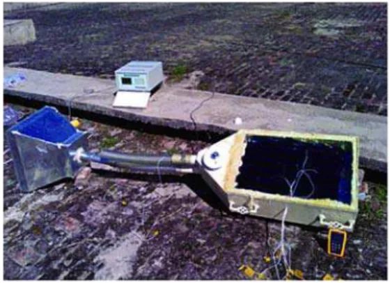
For this experimental study, a double pass SAH was fabricated using mild steel (fig. 1). Table 1 shows the general specifications of SAH. The bottom and side walls of heater were provided with 25 mm thick glass wool insulation. The top surface of heater was covered with a 5 mm window glass to receive the required solar radiation and to reduce the convection losses. Aluminum absorber plate was used. For
the integration of phase change TSM, five cop-per tubes were used and filled with paraffin wax (PW). The PW was first melted and then poured into the copper tubes. The absorber plate and copper tubes were painted black to absorb maximum solar radiation. Aluminum and stainless steel (SS) rods were also used and placed at the centre of the copper tubes in addi-tion to PW to check the heater’s performance for two other configurations. The heater was provided with conical inlet and outlet connec-tions and an exhaust fan was connected at the outlet to withdraw the heated air. The TBQ-type pyranometer having sensitivity of 11.36
µV/Wm2 and spectral range 280-3000 nm was used. The pyranometer was connected with the solar radiation monitoring system having a range of 0-2000 W/m2 and resolution of 1 W/m2 through a cable. The global solar irradiance is displayed on the LCD of data monitor-ing system. Calibration of pyranometer and solar monitormonitor-ing system was done by Pakistan Meteorological Department to within ±2%. For the measurement of temperatures at different locations of SAH, K-type thermocouples were used. These thermocouples were connected to
digital multimeter to read the temperature measurement. The temperatures were taken at five different positions on the absorb-er plate, one thabsorb-ermocouple was used for inlet air temperature and one for outlet air temperature and another one used to measure the temperature of lower glass sur-face. The thermocouples used had an accuracy of ±0.1 °C (ma-nufactured and calibrated by Omega). In order to calculate the energy stored in wax, Al and SS rods, one thermocouple was pla-ced in wax and one thermocouple was placed at the center of Al or SS rod by drilling a 1 mm hole in the rod.
Experiments were conduct-ed on double pass SAH for four different configurations. For each of the configuration, two consec-utive days readings were taken. The data was taken from 9 a. m. till 8 p. m. The heater was tilted at 34° (local latitude of Tax-ila, Pakistan) facing south to receive the solar radiation at its maximum. Figures 2(a) and (b) shows the schematic of the air heater and position of thermocouples, respectively.
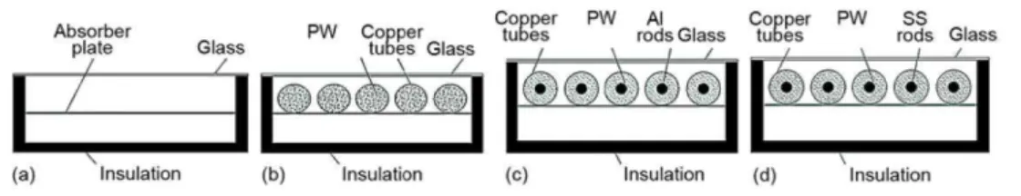
Figure 2. (a) double pass SAH schematic, (b) position of thermocouples
In the first configuration, fig. 3(a), no TSM was used. In the second configuration, fig. 3(b), copper tubes filled with PW were used. In the third configuration, fig. 3(c), alumi-num rods were placed at the center of the copper tubes and PW was filled at the outer periph-ery of the Al rods. In the fourth configuration, fig. 3(d), SS rods were placed at the center of the copper tubes with PW at the outer periphery of the SS rods.
The copper tubes were made to close at both of their ends by mean of threaded end caps, so that the possibility of leakage of PW is avoided. The flow rate of air as induced by the exhaust fan was calculated by first measuring the velocity of air by anemometer (resolu-tion 0.1 m/s, accuracy ±1%) and then from this velocity the flow rate was calculated:
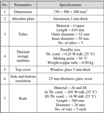
Table 1. Double pass SAH specifications
No. Parameters Specifications
1 Dimensions 750 × 500 × 200 mm3
2 Absorber plate Aluminum 2 mm thick
3 Tubes
Material = Copper Length = 610 mm Outer diameter = 52 mm Inner diameter = 50 mm
No. of tubes = 5
4
Thermal storage medium
Paraffin wax
Th. cond. = 0.25 W/mK (25 oC) Melting point = 56 °C Weight/copper tube = 0.90 kg
5 Top cover Window glass 5 mm thick
6 Side and bottom
insulation 25 mm thickness glass wool
7 Rods
Material = Al and SS Al Th. cond. = 205 W/mK (25 oC)
Figure 3. (a) configuration 1, (b) configuration 2, (c) configuration 3, (d) configuration 4
a = πr2 (1)
where a is the area of pipe, and r – the radius of pipe, and
m = ρaV (2)
where m is the air mass flow rate, ρ – the air density calculated at inlet temperature, and c – the air velocity.
The thermal efficiency of SAH is calculated using the following relations. For con-figuration 1, with no thermal energy storage medium:
Qin = Qsolar = IA (3)
where Qin is the input energy rate which is equal to solar energy rate i. e. Qsolar for
configura-tion 1.
Qout = mCpΔT (4)
where Qout is the output energy rate, Cp – the air specific heat capacity, calculated at average
of inlet and outlet temperature.
out 1
in Q
Q
η = (5)
where η1 is the thermal efficiency of configuration 1.
For configuration 2, with PW as phase change thermal energy storage medium:
Qin = Qsolar – Qstored (6)
where Qstored is the energy rate stored by wax i. e. Qwax for configuration 2 is:
w stored wax
T
Q Q MC
t ∆
= = (7)
where M is the mass of PW, C – the wax specific heat capacity calculated at measured wax temperature, and ∆Tw – the change in PW temperature in time t. Finally, thermal efficiency of
configuration 2 is calculated:
out 2
in Q
Q
η = (8)
For configuration 3, with PW and Al rods as thermal energy storage medium:
Qstored = Qwax + QAl (9)
a Al a a
T
Q M C
t ∆
= (10)
where Ma is the mass of Al rods, Ca – the Al specific heat capacity calculated at measured Al
rod temperature, and ∆Ta – the change in Al rod temperature in time t. Finally, thermal
effi-ciency of configuration 3 is calculated:
out 3
in Q
Q
η = (11)
For configuration 4, with PW and SS rods as thermal energy storage medium:
Qstored = Qwax + QSS (12)
where Qss is the rate energy stored by SS rods and is calculated:
S SS S S
T
Q M C
t ∆
= (13)
where Ms is the mass of SS rods, Cs – the SS specific heat capacity calculated at measured SS
rod temperature, and ∆Ts – the change in SS rod temperature in time t.
Finally, thermal efficiency of configuration 4 is calculated:
out 4
in Q
Q
η = (14)
Uncertainty analysis
The final parameters of interest (e. g. Qout, Qin, Qstored, etc.) were calculated using
measured experimental parameters i. e. air mass flow rate, inlet and outlet temperatures, solar irradiance, etc. Error caused by the uncertainties in the measured parameters into the final cal-culated parameters is estimated using Kline and McClintock [25] method. The maximum er-ror raised in Qout was just under 5%; air mass flow rate, and inlet and outlet temperatures
found to be equally important for the propagation of this error.
Results and discussion
For each of the configuration, two consecutive days readings were taken and are presented here for analysis. The data were taken from 9 a. m. till 8 p. m. The heater was tilted at 34o (local latitude of Taxila, Pakistan) facing south to receive the solar radiation. The graphs for inlet air temperature, outlet air temperature, absorber plate temperatures, heat in-put, heat outin-put, and thermal efficiency are considered for analysis.
(a) (b)
(c) (d)
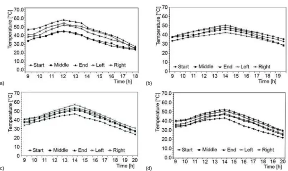
Figure 4. Absorber plate temperature at different locations as a function of time; (a) configuration 1, (b) configuration 2, (c) configuration 3, (d) configuration 4
Figure 5 shows the intensity variation of solar flux as a function of time for all four configurations. It can be seen that the variation in solar flux and trend is almost the same for all configurations. Solar energy becomes almost zero after 6 p. m.
Figure 6 shows the comparison of the temperature differences (outlet minus inlet) as a function of time for all four configurations. It can be seen that for configuration 1, with no thermal energy storage medium, temperature difference is greater at the start of the day as com-pared to other configurations, it is due to the fact that almost all of the energy absorbed by the absorber plate (excluding the losses through apparatus) is available for heating the incoming air by convection since no thermal energy storage medium is used. Also for this configuration, the highest temperature difference was observed around noon when the solar flux was maximum, after that temperature difference started decreasing and became zero at about 6 p. m.
Figure 5 – Solar flux variation as a function of time for all configurations
For other configurations with TSM, in contrast with configuration 1, temperature differences (outlet minus input) were lower than configuration 1 till about 2 p. m. (fig. 6). This is due to the fact that in the earlier part of the day, a part of the solar energy received, was kept storing by the TSM, as a consequence less energy was available to heat the air by convection. However, after 2 p. m., when solar flux started decreasing, the stored energy re-leased and participated to heat the air by convection. As a result higher temperature differ-ences were achieved after 2 p. m. compared to configuration 1. Also, as can be seen from the figure, for these configurations temperature difference was available even after 6 p. m. that was used to heat air after sunset up to few more hours.
Configurations 2, 3, and 4 contain TSM i. e., PW, PW plus Al rod in the center, and PW plus SS rod in the center. As explained in fig. 6, temperature difference was available for configuration 2 up to 7 p. m. and for configurations 3 and 4 up to 7:30 p. m. In order to under-stand the superiority of configurations 3 and 4 (i. e. with Al and SS rods in the center of tubes) over configuration 2 (only filled with PW), fig. 7 is presented. As can be seen from fig. 7, till 2 p. m. configurations 3 and 4 store energy at a higher rate compared to configura-tion 2. Also, after 2 p. m. the rate of release of energy for configuraconfigura-tions 3 and 4 is generally more consistent and prolonged as compared to configuration 2. This is due to the fact that for configuration 2 (only with PW) when initially receives energy, this energy melts the PW as latent energy. Once on the upper part of tube, PW is melted then its temperature starts increas-ing creatincreas-ing a temperature gradient which leads to a sensible heat transfer. So for configura-tion 2, PW present at the lower part of tube takes long time to melt. On the other hand, for configurations 3 and 4, rods inserted at the middle of the tubes surrounded by PW act as a thermal enhancer due to their higher value of thermal conductivity. This helps more effective-ly for the transfer of energy to the PW in the lower part of tube, so energy received by the tube absorbs as latent energy. It should be noted that configuration 3 stores energy at margin-ally higher rates compared to configuration 4, because Al has higher value of thermal conduc-tivity compared to SS.
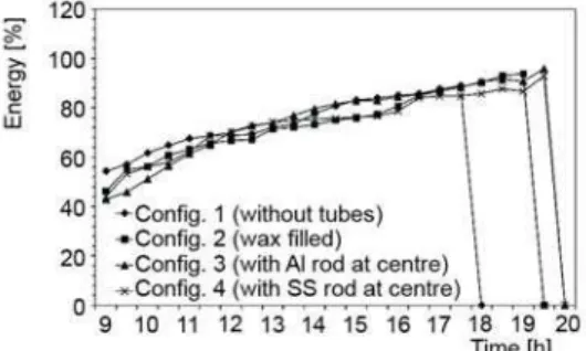
Figure 8 compares the efficiency variation as a function of time for four configura-tions of double pass SAH. It can be seen that for configuration 1, at the start of the day effi-ciency was higher than other configurations which was due to the well explained fact that a part of energy was stored in the configurations with TSM. However, in the later part of day (onward 12 p. m. to 5:30 p. m.), this difference in efficiency variation decreased. For configu-ration 1, maximum efficiency achieved was 88% at 5:30 p. m. Configuconfigu-ration 2, provided use-ful heat till 7 p. m. (i. e. 1:30 hours more than the configuration 1 after sunset), with a maxi-mum efficiency value of 91% at 7 p. m. Configurations 3 and 4, gave the prolonged
perfor-Figure 7. Energy store/release rate for configurations 2, 3, and 4
mance till 7:30 p. m. (i. e. 2 hours more than configuration 1 after sunset) researched to their maximum efficiencies values of 93% and 96%, respectively, at 7:30 p. m.
Conclusions
A double pass SAH was investigated experimentally for four different configura-tions. Following important results were found.
● By using TSM in a double pass SAH, energy can be used effectively to operate heater af-ter the sunset.
● A simple TSM i. e. PW can only be used to store energy to use it after sunset; however, it has its limitations. In present investigation, configuration 2 (with PW only) provided use-ful heat for about 1.5 hours more than the configuration 1 (without any TSM).
● By using a thermal enhancer in a TSM, as used in configurations 3 and 4 (Al and SS rods) more energy can be stored (compared to simple thermal energy storage medium i. e. PW) during the earlier hours of the day. Configurations 3 and 4 provided useful heat for about 2 hours more than configuration 1.
● The maximum efficiency of about 96% was achieved using configuration 3 (i. e. using Al rods with PW).
● More effective arrangements of thermal enhancer materials in a TSM can be employed and analyzed for a double pass SAH to store energy more effectively in future.
Nomenclature
A – collector area, [m–2]
a – cross-sectional area of pipe, [m–2]
C – specific heat of PW, [Jkg–1K–1]
Ca – specific heat of aluminum, [Jkg–1K–1]
Cp – specific heat of air, [Jkg–1K–1]
Cs – specific heat of SS, [Jkg–1K–1]
I – solar radiation intensity, [Wm–2]
M – total mass of PW, [kg]
Ma – total mass of aluminum rods, [kg]
Ms – total mass of SS rods, [kg]
m – mass flow rate of air, [kgs–1]
Qal – energy stored by aluminum, [W]
Qin – heat input, [Wm–2]
Qout – heat output, [Wm–2]
Qsolar – energy received from solar radiation, [Wm–2]
Qss – energy stored by SS rods, [Wm–2]
Qstored – energy stored, [Wm–2]
Qwax – energy stored by PW, [Wm–2]
r – inlet pipe radius, [m]
∆Tw – temperature difference of PW for time t, [K]
∆Ta – temperature difference of aluminum for time t, [K]
∆Ts – temperature difference of SS for time t, [K]
t – time for which the energy is stored, [s] V – velocity of air, [ms–1]
Greek symbols
η1 – thermal efficiency for configuration 1
η2 – thermal efficiency for configuration 2
η3 – thermal efficiency for configuration 3
η4 – thermal efficiency for configuration 4
ρ – density of air, [kgm–3] Acronyms
LCD – liquid crystal display PW – paraffin wax SAH – solar air heater SS – stainless steel
TSM – thermal storage medium
References
[1] Krishnananth, S. S., Murugavel, K. K., Experimental Study on Double Pass Solar Air Heater with Ther-mal Energy Storage, Journal of King Saud University-Engineering Sciences, 25 (2013), 2, pp. 135-140
[2] Fath, H. E. S., Thermal Performance of a Simple Design Solar Air Heater with Built-in Thermal Energy Storage System, Energy Conversion & Management, 36 (1995), 10, pp. 989-997
[3] Velmuruganl, P., Kalaivanan, R., Evaluation of Thermal Performance of Wire Mesh Solar Air Heater,
Indian Journal of Science and Technology, 4 (2011), 1, pp. 12-14
[4] Yeh, H.-M., Ting, Y.-C., Effects of Free Convection on Collector Efficiencies of Solar Air Heaters,
[5] Prasad, S. B., et al., Investigation of Heat Transfer and Friction Characteristics of Packed Bed Solar Air Heater using Wire Mesh as Packing Material, Solar Energy, 83 (2009), 5, pp. 773-783
[6] Akpinar, E. K., Kocyigit, F., Experimental Investigation of Thermal Performance of Solar Air Heater Having Different Obstacles on Absorber Plates, International Communications in Heat and Mass
Trans-fer, 37 (2010), 4, pp. 416-421
[7] Hernandez, A. L., Quinonez, J. E., Analytical Models of Thermal Performance of Solar Air Heaters of Double-Parallel Flow and Double-Pass Counter Flow, Renewable Energy, 55 (2013), July, pp. 380-391 [8] Sharma, S. P., et al., Thermal Performance of Packed-Bed Solar Air Heaters, Solar Energy, 47 (1991), 2,
pp. 59-67
[9] El-Sebaii, A. A., Al-Snani, H., Effect of Selective Coating on Thermal Performance of Flat Plate Solar Air Heaters, Energy, 35 (2010), 4, pp. 1820-1828
[10]Naphon, P., Effect of Porous Media on the Performance of the Double-Pass Flat Plate Solar Air Heater,
International Communications in Heat and Mass Transfer, 32 (2005), 1-2, pp. 140-150
[11]Demireli, Y., Kun, S., Thermal Performance Study of a Solar Air Heater with Packed Flow Passage,
En-ergy Conversion and Management, 27 (1987), 3, pp. 317-325
[12]Bhargava, A. K., Rizzi, G., A Solar Air Heater with Variable Flow Passage Width, Energy Conversion
and Management, 30 (1990), 4, pp. 329-332
[13]Garg, H. P., et al., A Study on the Effect of Enhanced Heat Transfer Area in Solar Air Heaters, Energy
Conversion and Management, 23 (1983), 1, pp. 43-49
[14]Indrajit. N. K., et al., An Experimental Study on a Finned Type and Non-Porous Type Solar Air Heater with a Solar Simulator, Energy Conversion and Management, 25 (1985), 2, pp. 135-138
[15]El-Khawajah , et al., The Effect of using Transverse Fins on a Double Pass Flow Solar Air Heater using Wire Mesh as an Absorber”, Solar Energy, 85 (2011), 7, pp. 1479-1487
[16]Omojaro, A. P., Aldabbagh, L. B. Y., Experimental Performance of Single and Double Pass Solar Air Heater with Fins and Steel Wire Mesh as Absorber, Applied Energy, 87 (2010), 12, pp. 3759-3765 [17]Mohammadi, K., Sabzpooshani, M., Comprehensive Performance Evaluation and Parametric Studies of
Single Pass Solar Air Heater with Fins and Baffles Attached over the Absorber Plate, Energy, 57 (2013), Avg., pp. 741-750
[18]Wijeysundera, N. E., et al., Thermal Performance Study of Two-Pass Solar Air Heaters, Solar Energy,
28 (1982), 5, pp. 363-370
[19]Badescu, V., The Dependence of Solar Air Heater Performance Upon Tilt and Orientation, Energy
Con-version & Management, 30 (1990), 2, pp. 179-185
[20]Ho, C.-D., et al., Performance Improvement of Wire Mesh Packed Double-Pass Solar Air Heaters with External Recycle, Renewable Energy, 57 (2013), Sep., pp. 479-489
[21]El-Sebaii, A. A., et al., Year Round Performance of Double Pass Solar Air Heater with Packed Bed,
En-ergy Conversion and Management, 48 (2007), 3, pp. 990-1003
[22]Al-Kamil, M. T., Al-Ghabeeb, A. A., Effect of Thermal Radiation inside Solar Air Heaters, Energy
Con-version and Management, 38 (1997), 14, pp. 1451-1458
[23]Aldabbagh, L. B. Y., et al., Single and Double Pass Solar Air Heaters with Wire Mesh as Packing Bed,
Energy, 35 (2010), 9, pp. 3783-3787
[24]Ozgen, F., et al., Experimental Investigation of Thermal Performance of A Double-Flow Solar Air Heat-er Having Aluminum Cans, Renewable EnHeat-ergy, 34 (2009), 11, pp. 2391-2398
[25]Kline, S. J., McClintock, F. A., Describing Uncertainties in Single-Sample Experiments, Mech. Eng., 75 (1953), Jan., pp. 3-8