ISSN 1553-345X
© 2009 Science Publications
Corresponding Author: Ebrahim M. Ali Alfegi, Solar Energy Research Institute, University Kebangsaan Malaysia, 43600 UKM Bangi, Selangor Darul Ehsan, Malaysia
Mathematical Model of Double Pass Photovoltaic Thermal Air Collector with Fins
Ebrahim M. Ali Alfegi, Kamaruzzaman Sopian, Mohd Yusof Hj Othman and Baharudin Bin Yatim
Solar Energy Research Institute, University Kebangsaan Malaysia, 43600 UKM Bangi,
Selangor Darul Ehsan, Malaysia
Abstract: Problem statement: The efficiency of photovoltaic cells is generally temperature dependent (efficiency decrease when the temperature of the photovoltaic cells increase). This problem can be solved by cooling the solar cells during operation and operated at low temperature. Approach: This study presented a numerical model of double pass Photovoltaic Thermal (PV/T) solar air collector with fins attached to the back side of the absorber plate to improve heat transfer to the flowing air for predicting the performance of the system. Results: Five coupled of unsteady nonlinear partial differential equations were formulated by using first order forward scheme in time and second order central difference scheme in space to predict the performance of PV/T solar air heater at different parameters and conditions. The temperatures of the solar cells, outlet fluid temperature and the temperature distribution of every static element in both models were predicted. The performance of the collector including photovoltaic, thermal and combined PV/T collector over range of operating conditions are discussed. Conclusion: Experimental and theoretical results were compared and showed that close agreement between these two values were obtained.
Key words: Hybrid PV/T solar collector, fin, performance analysis, unsteady state analysis INTRODUCTION
Hybrid photovoltaic thermal PV/T solar collector combines PV cells with a solar thermal unit as a composite absorber, thus generates electricity and heat simultaneously when solar radiation falls on it. Heat generated by the PV modules when solar radiation falls on it is converted into waste heat, causing a decrease in PV efficiency. This undesirable effect can be partially avoided by applying a heat recovery unit with fluid circulation (air or water) over PV module to keep the module electrical efficiency at acceptable level.
Extensive investigations have been carried out by many researchers on the design optimization of this hybrid collector in search of efficient and inexpensive designs suitable for mass production for different practical applications. Ong[2] carried out a steady state mathematical model and solution procedure for predicting the thermal performance for four common types of flat plate solar air collector designs. Sopian et al.[3] presented new design of double-pass PV thermal air collector, the performance of single pass and double pass combined PV/T air collectors were analyzed under steady state conditions. Garg and Adhikar[4] presented a computer simulation model for predicting the transient performance of PV/T air
593 state. Assoa et al.[13] developed simplified steady state 1-D mathematical model of PV/T air and water based collector with a metal absorber. Tonui and Tripanagnostopoulos[14] carried out experimental tests on PV/T air based solar collector and run it under steady state forced and natural air flow modes. Tripanagnostopoulos[15] performed an experimental study on PV/T collector with dual heat extraction operation, either with water or with air circulation.
To ensure good flow distribution across the flow channel it is necessary that the area of the channel is large. However, it is also necessary to keep the pressure drop low so that the energy spent in pumping the air through the channel is low to make the system cost effective. The use of a double pass resulted in an increase in the pressure drop across the collector. However, the increase in the operating cost due to the increased pressure drop in the collector is considered small.
This study reports numerical model of a double pass PV/T solar air collector with fins for predicting the performance of the system.
MATERIALS AND METHODS
Modeling: The double pass PV/T solar collector presented in this study has three essential static components: A glazing on the top, a plate containing numerous solar cells and a bottom plate as depicted in Fig. 1. Detailed heat balance equations for these components, including those concerning both upper and lower air stream moving through the collector are given below. The air enters through the channel formed by the glass cover and the PV plate and then through the lower channel as shown in Fig. 1.
One of the advantages of having two channels stems from the possibility of the air to be heated twice. Thus, more thermal energy should be transferred to the air compared with any one-pass PV/T collector. The subsequent mathematical formulation has been written under the following assumptions:
• Air behaves as an incompressible fluid
• The temperatures of the glass cover, solar cells and plates are varying only in the direction of working fluid flow. Moreover, we limit our study from x = 0 to x = L and assume Tf1 (L,t) = Tf2 (L,t) at anytime
• The thermal contact between solar cells and the absorber where they are mounted on is good enough for not making the distinction between their respective temperatures
Fig. 1: Schematic diagram of double pass (PV/T) air collector with fins
Fig. 2: Schematic diagram of heat transfer coefficients in the double pass PV/T air collector with fins
• Heat losses are neglected since we assume that both channels are correctly sealed preventing any leakage of air from the collector
• The glazing, the photovoltaic plate and the bottom plate are thin enough to consider their respective temperature as equal over the entire thickness
• The model uses only total irradiation
• Long wavelengths and short wavelength radiation are not taken into consideration
The schematic diagram of the double pass PV/T solar air collector with heat transfer coefficients is shown in Fig. 2.
The thermal energy balance equations for the different nodes of the system are as follows:
For glass cover:
g
g g pg g rg,s s g cg,w w g
cg,f1 f1 g rg,p p g
T
t C I h (T T ) h (T T )
t
h (T T ) h (T T )
∂
ρ = α + − + −
∂
+ − + −
For air stream in upper channel:
.
f1 pf1
f1 f1
1 f1 pf1 cg,f1 g f1 cp,f1 p f1
m C
T T
H C h (T T ) h (T T )
t W x
−
∂ ∂
ρ = + − + −
For absorber plate:
p p pp g p g pv pv
cp,f1 f1 p rp,g g p
ab(B)
cp,f 2 p f 2 p
c
ab(B)
rp,bp bp p
c
Tp
t C I (1 P) I(1 )P
t
h (T T ) h (T T )
A
h (T T ) A
A
h (T T ) A
∂
ρ =τ α − +τ α −η
∂
+ − + −
+ η −
+ − Where: fin p f ab(B) f f f
pv ref pav ref
1 2 c
f f
A
1 (1 )
A
tanh mh mh
(1 0.0054(T T ))
2h m
k t
η = − − η
η =
η = η − −
=
For air stream in lower channel:
.
f 2 pf 2
f 2 f 2
2 f 2 pf 2 cbp,f 2 bp f 2
ab(B)
cp,f 2 p p f 2
c
m C
T T
H C h (T T )
t W x
A
h (T T ) A
−
∂ −∂
ρ ∂ = ∂ + −
+ η −
For back plate:
bp
bp bp pbp b a bp cbp,f 2 f 2 bp
ab(B)
rp,bp p bp
c
T
t C U (T -T ) h (T T )
t
A
h (T T ) A
∂
ρ = + −
∂
+ −
Many heat transfer coefficient expressions are available in literature. The radiative and convective heat transfer coefficients from top surface to the sky and between two parallel plates are obtained from Ong[2] as follows:
2 2
g g s g s g s
rg,s
g a
(T T )(T T )(T T ) h
(T T )
σε + + −
=
−
2 2
g p g p
rp,g
g p
(T T )(T T ) h
1 1
( 1)
σ + +
=
+ −
ε ε
where, (Ts) is the sky temperature and calculated as:
1.5
s a
T =0.0552 T
We will utilize the same above expression to compute the radiative heat transfer coefficient (hrp,bp).
The convective heat transfer coefficient in enclosed spaces is calculated by the Nusselt number which is defined by: h u hD N k = Where: f h
4A 4(W * H)
D
perimeter 2(W H)
= =
+
The correlation for the convective heat transfer coefficient (hw) with the speed of wind (Vwind) on the surface of the collector was suggested by Mc Adam[16] as:
w wind
h =5.7+3.8V
Kays[17] formulated the convective heat transfer coefficient in the upper channel which is forced convection. The force convective heat transfer coefficient depends on the Reynolds number (Re) that flow through the certain channel. The flow can be divided into three regimes of flow as:
Laminar flow regime (Re < 2300):
m h e r
u u n
h e r
D a R P
L N (N )
D 1 b R P
L ∞ = + + Where:
a = 0.00190 b = 0.00563 m = 1.71 N = 1.17 (Nu)∞= 5.4 Pr = 0.7
Transition flow regime (2300 < Re < 6000):
2 0.14
2 1 3
h
3 3
u e r
w
D N 0.116 R 125 P 1
L
µ
= − + µ
Turbulent flow regime (Re > 6000):
0.8 0.4
u e r
595 The empirical equation to calculate the heat transfer coefficient inside the channel formed by the back surface of the absorber plate with fins and the back plate of the collector has formulated by Manglik and Bergless[1] as:
1
0.4597 0.1541 0.1499 0.0678 3
u r e
0.1 5 1.340 0.504 0.456 1.055
e
N 0.6522P R * 1 5.269 *10 R
− −
− −
= β δ γ
+ β δ γ
The physical properties of air are assumed to vary linearly with temperature owing to low temperature range to be encountered. The expressions for as functions of temperature are available from Ong[2]. Dynamic viscosity:
5
1.983 0.00184(T 27) *10− µ = + −
Density:
1.1774 0.00359(T 27)
ρ = − −
Thermal conductivity:
k=0.02624+0.0000758(T−27)
Specific heat:
p
C =1.0057+0.000066(T−27) *1009
The performance parameters of combined photovoltaic thermal solar collector are obtained in terms of the thermal efficiency and electrical efficiency as:
PV / T thermal electrical
η = η + η
.
p o i E
PV / T
c
m C (T T )dt P dt
A Idt Idt
−
η =
∫
+∫
∫
∫
Solution procedures: Based on the first order forward scheme in time and second order central difference scheme in space to predict the PV/T solar air heater at different parameters and conditions, an explicit transient model was developed for the double pass PV/T air collector with fins. An explicit transient analysis can be worked on through solving the transient energy balance equations for the various collector components.
The first order forward scheme in time is as follows:
j, n 1 j, n
T T T
t t
+
∂ = −
∂ ∆
The second order central difference scheme in space is as follows:
j 1, n j 1,n
T T T
x 2 x
+ −
∂ = −
∂ ∆
2 j 1, n j,n j 1,n
2 2
T T 2T T
x x
+ −
∂ = − +
∂ ∆
The energy balance equations are subjected to the following boundary conditions:
For x = 0, x = L:
g p bp
f 1
f 1 measured
x L , t 0
f 1 f 2
T T T
0
x x x
T
T (0, t) T (t ) 0
x
T (L, t) T (L, t)
= = ∂ ∂ ∂ = = = ∂ ∂ ∂ ∂ = = ∂ =
No boundary condition is assigned to the second air stream temperature at the exit of the lower channel. Indeed, we will compute Tf2 (0,t) at x = 0.
The space interval [0,L] is decretized by the Nx + 1 following points xj = jδx where j = 0,1,…,Nx and δx = L/Nx. Similarly, time interval [0,t] is divided by
the instants tn = nδt where n = 0,1,…., Nt and δt = t/ Nt.
We solve energy balance equations along with their boundary conditions, the first order forward scheme and second order central difference scheme which applied for example to equation for air stream in upper channel yields:
.
j,n 1 j,n j 1,n j 1,n
f1 pf1
f1 f1 f1 f1
1 f1 pf1
cg,f1 g f1 cp,f1 p f1
m C
T T T T
H C
t W 2 x
h (T T ) h (T T )
+ − + −
− −
ρ =
∆ ∆
+ − + −
The final formula for the above equation is as follow:
.
j 1,n j 1,n
f1 pf1 f1 f1
j,n 1 j,n
f1 f1
1 f1 pf1
cg,f1 g f1 cp,f1 p f1
m C T T
t
T T W 2 x
H C
h (T T ) h (T T )
+ − + − − ∆ = + ∆
ρ
+ − + −
We proceed in the same way for other energy balance equations.
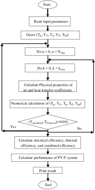
simulate the transient performance of the system at a time interval of 0.0001 min. Its inputs require radiation intensity, mass flow rate and inlet temperature while its outputs contain the temperature of the glass cover, absorber plate with photovoltaic cells, back plate and air flow in both channels. The output data used to determine the efficiency of PV/T system. The flow chart in Fig. 3 shows the key steps in the simulation program is capable to determine the performance of photovoltaic thermal collectors with any input parameters changes.
Read input parameters
Gu ess (Tg, Tf1, Tp, Tf2, Tbp)
Do n = 0, n = Nmax
Calculate Physical properties of air and heat transfer co efficients
Nu merical calculation of (Tg, Tf1, Tp, Tf2, Tbp)
Calculate electrical efficiency, thermal efficien cy, and combined efficiency
Start
Yes No
En d
Calculate performance of PV/T system
Print result Do k = 0, k = kmax
(Tcalc ula ted-TG uesse d)<0.0 01
Fig. 3: The flow chart to calculate the performance of the double pass PV/T air collector with fins
RESULTS AND DISCUSSION
The effect of mass flow rate on temperature of photovoltaic cells is shown in Fig. 4. Results show that by increasing the mass flow rate the photovoltaic cell Temperature (Ts) decrease at all radiation intensity used. At same mass flow rate, photovoltaic Temperature (Ts) is increase at increasing radiation intensity. It can see this increasing obvious at low mass flow rate and by increasing of mass flow rate; the differences of photovoltaic Temperature (Ts) are getting smaller. As known well, increasing photovoltaic temperature will decrease the photovoltaic efficiency. Therefore, photovoltaic cell temperature must be reduced to increase the photovoltaic efficiency.
Air mass flow rate has an effect on temperature rise of the collector which is the differences in temperature between the outlet temperature and inlet temperature (To-Ti) is shown in Fig. 5. Results show that the temperature rise (To-Ti) is decrease when mass flow rate increase at various operating conditions. Temperature rise at radiation intensity of 400 W m−2 and inlet temperature of 30°C decrease from 4.649°C at mass flow rate of 0.0316 kg sec−1 to 2.112°C at mass flow rate of 0.09 kg sec−1. From Fig. 5, it can see that at certain mass rate flow, temperature rise (To-Ti) for higher radiation intensity bigger than low radiation intensity.
Changes mass flow rate on photovoltaic cell temperature gives clear effect to the electrical efficiency. Also, changes mass flow rate on temperature rise gives clear effect to the thermal efficiency of the PV/T collector. Effect on electrical and thermal efficiencies will give effect on combined efficiency which the sum of electrical and thermal efficiencies.
597 Fig. 5: Changes on temperature rise versus changes of
mass flow rate at various intensity of radiation and [Ti = 30°C]
Fig. 6: The effect of mass flow rate on photovoltaic, thermal and combined photovoltaic thermal efficiencies at radiation intensity of [I = 700 W m−2] and [Ti = 30°C]
Figure 6 show the effect of mass flow on photovoltaic, thermal and combined photovoltaic thermal efficiencies. Generally, it can be observed that collector operating at higher mass flow rate will increase the efficiencies. Also, it is found that the theoretical results are higher than experimental results. The trend between experimental and theoretical photovoltaic efficiency is very close together. Otherwise, trend between experimental and theoretical thermal and combined photovoltaic efficiencies are converging at low flow rate. Meanwhile, it’s diverging with acceptable agreement at high flow rates. The reason for this
diverging is the value of heat transfer coefficient chosen in the theoretical analysis.
CONCLUSION
A hybrid photovoltaic-thermal (PV/T) solar collector was theoretically and experimentally studied. The simulation model can predict the performance of the system such as air outlet temperature, electrical, thermal and combined efficiencies for different air mass flow rates, radiation intensity and inlet temperatures. The study shows that the predicted results were in good agreement with the experimental results which were conducted in the laboratory of University Kebangsaan Malaysia. Thus the proposed mathematical model can be used to predict quite accurately the temperatures of all static parameters of the double pass PV/T solar collector. The model has to be completed in further developments and the collector has to be tested in real conditions. It can also be concluded that by using fins as an integral part of the absorber surface, can achieve significant meaningful efficiencies for both thermal and electrical output of the hybrid PV/T solar collector.
ACKNOWLEDGEMENT
This research was partially supported by the Solar Energy Research Institute (SERI), University Kebangsaan Malaysia. The authors wish to thank The Solar Energy Research for their support.
REFERENCES
1. Manglik, R.M. and A.E. Bergles, 1995. Heat transfer and pressure drop correlations for the rectangular offset strip fin compact heat exchanger. Exp. Thermal Fluid Sci., 10: 171-180. http://cat.inist.fr/?aModele=afficheN&cpsidt=3451319 2. Ong, K.S., 1995. Thermal performance of solar air
heaters: Mathematical model and solution procedure. Solar Energ., 55: 93-109.[
3. Sopian, K., K.S. Yigit, H.T. Liu, S. Kakac and T.N. Veziroglu, 1996. Performance analysis of photovoltaic thermal air heaters. Energy Conv.
Manage., 37: 1657-1670.
http://cat.inist.fr/?aModele=afficheN&cpsidt=3084 865
4. Garg, H.P. and R.S. Adhikari, 1998. Transient simulation of conversional hybrid photovoltaic/thermal (PV/T) air heating collectors.
Energy Res., 22: 547-62.
5. Garg, H.P. and R.S. Adhikari, 1999. Performance analysis of a hybrid Photovoltaic/Thermal (PV/T) collector with integrated CPC troughs. Energy
Res., 23: 1295-304.
http://cat.inist.fr/?aModele=afficheN&cpsidt=1201 042
6. Hegazy, A.A., 2000. Comparative study of the performance of four photovoltaic/thermal solar air collectors. Energy Conver. Manage., 41: 861-881. http://cat.inist.fr/?aModele=afficheN&cpsidt=1258 699
7. Sopian, K., K.S. Yigit, H.T. Liu, S. Kakac and T.N. Veziroglu, 2000. Performance of a double pass photovoltaic thermal solar collector suitable for solar drying system. Energy Conver. Manage., 41: 53-365.
http://cat.inist.fr/?aModele=afficheN&cpsidt=1221 279
8. Sopian, K. and M.Y. Othman, 2000. On the cost-effectiveness of photovoltaic thermal solar collector. Proceeding of the World Renewable Energy Congress, July 1-7, Brighton, pp: 2057-2060. http://cat.inist.fr/?aModele=afficheN&cpsidt=1417 5767
9. Tripanagnostopoulos, Y., Nousia, Th., M. Souliotis and P. Yianoulis, 2002. Hybrid photovoltaic/thermal solar system. Solar Energy, 72: 217-234.
http://direct.bl.uk/bld/PlaceOrder.do?UIN=109564 254&ETOC=RN&from=searchengine
10. Zondag, H.A., D.W. de Vries, W.G.J. Van Hendel, R.J.C. Van Zolingen and A.A. Van Steenhoven, 2003. The yield of different combined Pv-thermal collector designs. Solar Energy, 74: 253-269. http://cat.inist.fr/?aModele=afficheN&cpsidt=1497 9679
11. Othman, M.Y., B. Yatim, K. Sopian and M.N. Abu Bakar, 2005. Performance analysis of a double-pass Photovoltaic/Thermal (PV/T) solar collector with CPC and fins. Renewable Energy, 30: 2005-2017.
http://cat.inist.fr/?aModele=afficheN&cpsidt=1698 3022
12. Othman, M.Y., B. Yatim, K. Sopian and M.N. Abu Bakar, 2007. Performance studies on a finned double-pass Photovoltaic-Thermal (PV/T) solar collector. Desalination, 209: 43-49. http://cat.inist.fr/?aModele=afficheN&cpsidt=1879 9303
13. Assoa, Y.B., C.G. Menezo, R. Fraisse, Yezou and J. Brau, 2007. Study of a new concept of photovoltaic-thermal hybrid collector. Solar
Energy, 81: 1132-1143.
http://cat.inist.fr/?aModele=afficheN&cpsidt=19118349 14. Tonui, J.K. and Y. Tripanagnostopoulos, 2007.
Improved PV/T solar collectors with heat extraction by forced or natural air circulation. Renewable Energy, 32: 623-637. DOI: 10.1016/j.renene.2006.03.006
15. Tripanagnostopoulos, Y., 2007. Aspects and improvements of hybrid photovoltaic/thermal solar energy systems. Solar Energy, 81: 1117-113. http://cat.inist.fr/?aModele=afficheN&cpsidt=1911 8348
16. McAdam, W.H., 1954. Heat Transmission. 3rd Edn., McGraw-Hill Book Company, New York., pp: 532. http://books.google.com.pk/books?id=AgtRAAAA MAAJ&q=Heat+Transmission&dq=Heat+Transmi ssion

![Fig. 6: The effect of mass flow rate on photovoltaic, thermal and combined photovoltaic thermal efficiencies at radiation intensity of [I = 700 W m −2 ] and [Ti = 30°C]](https://thumb-eu.123doks.com/thumbv2/123dok_br/18375616.355794/6.918.147.409.134.386/photovoltaic-thermal-combined-photovoltaic-thermal-efficiencies-radiation-intensity.webp)
