INTELLIGENT DTC FOR PMSM DRIVE
USING ANFIS TECHNIQUE
AHMED A. MAHFOUZ
Professor of Electrical Power & Machines, Faculty of Engineering, Cairo University Giza, Egypt
WAEL MOHAMED MAMDOUH
Electrical Power Engineer, Science & Technology Center of Excellence Cairo, Egypt
Abstract
This paper describes intelligent direct torque control (DTC) technique for Permanent Magnet Synchronous Motor (PMSM) drive based on Adaptive Neuro Fuzzy Inference Systems (ANFIS). The proposed system has proven successful in controlling the instantaneous torque so as not to depend only on the estimation flux, torque and position, but also the estimation of the lookup table and the generation of driver switching table. Experimental results prove the MATLAB simulation results for torque, speed and flux estimations.
Keywords: DTC; PMSM; ANFIS; Drive.
1. INTRODUCTION
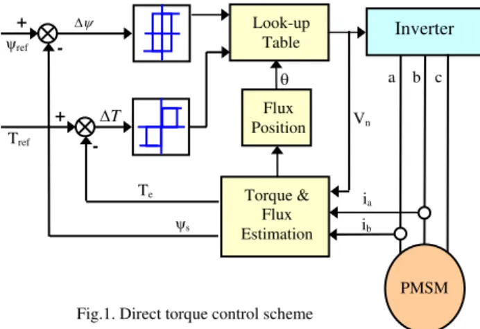
A simplified variation of field orientation known as direct torque control (DTC) was developed by Takahashi and Depenbrock [1]. Figure1 shows a DTC of PMSM. In direct torque controlled PMSM drives, it is possible to control directly the stator flux linkage and the electromagnetic torque by the selection of an optimum inverter switching state. The selection of the switching state serves two functions: the flux and the torque errors within their respective hysteresis bands and to obtain the fastest torque response and highest efficiency at every instant. DTC is simpler than field-oriented control and less dependent on the motor model, since the stator resistance value is the only machine parameter used to estimate the stator flux. One of the disadvantages of DTC is the high torque ripple. Under constant load at steady state, an active switching state causes the torque to continue to increase past its reference value until the end of the switching period; then a zero voltage vector is applied for the next switching period causing the torque to continue to decrease below its value. Direct torque control (DTC) is considered as one of the best alternatives for motor drive designers in order to get a fast torque response; especially when torque control instead of speed or position control, is the control objective. Besides high torque dynamics, it is well known for being robust to motor parameters change, except the stator resistance [2]. The flux command is usually kept constant and equal to the nominal value for speeds under the nominal speed. However, this does not give the maximum torque to amp ratio.
In section I, The proposed technique looks for an optimal voltage vector that results in a maximum torque change in each sampling time. In Section II, the model of an Interior Permanent Magnet (IPM) machine, besides the fundamentals of DTC, is presented. To show the relationship between the flux command and torque dynamics, the effect of choosing different flux commands for the same machine is investigated in Section III. In Section IV, a new real time strategy is presented to estimate the torque, speed, and flux using ANFIS technique in order to get rapid torque dynamics in a low cost way.
Section V discusses the experimental results. Finally, section VI summarizes the conclusion and the main contributions of this paper.
2. IPM MACHINE MODEL AND DTC FUNDAMENTALS
Using the d–q transformation, the voltage equations of an IPM machine in the rotor reference frame are as follows [5]:
d e q
d s d
dt
d
i
R
v
(1)d e q q s q dt d i R
v (2)
Where ψd = Ldid + ψm , ψq = Lqiq and the stator flux linkage is ψs = (ψd + ψq)2. The corresponding equivalent
circuits are shown in figure 2.
It has been shown that the electromagnetic torque in an IPM machine can be regulated by controlling the magnitude and angle of the stator flux linkage or load angle that is seen in figure 4 [10].
This can be performed by applying the proper output voltage vectors of an inverter to the machine.
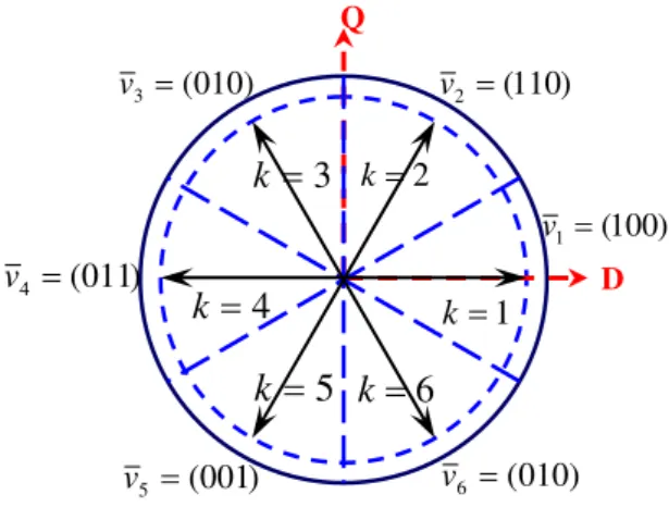
There are six nonzero voltage vectors and two zero voltage vectors for a two level inverter as depicted in figure 3. They can be represented by:
. 6 6 , 6 ; k k k k k
Where k is the sector number,
) (
3
2 23 j43
c j b a DC
s V S S e S e
v
Sa, Sb and Sc are used to show the state of each leg in the inverter, which is either 0 or 1. They are 0 when the leg
is connected to zero and 1 when it is connected to the DC bus voltage VDC. It has also been proved that the torque dynamics is dependent on the speed of rotation of the stator flux linkage with regard to the magnet flux
linkage. In other words, to get a fast torque response, one should increase the load angle as quickly as
Look-up Table Torque & Flux Estimation Flux Position Inverter PMSM + + --
Fig.1. Direct torque control scheme
T
a b c
ia ib ψs Te Tref ψref Vn
+
_
+ -q e d v Direct axis+
_
+ -d e q v Quadrature axisFig. 2. Equivalent circuit model. s
R Ld Rs Lq
d
possible. There are two different inverter switching tables introduced for IPM machines [9]. One of the switching tables is suitable for low speed operation. Table 1 is such a switching table that does not use zero voltages to decrease the machine torque.
After sampling the motor voltages and currents, the stator flux magnitude and machine torque are estimated as:
vs Rsis
dt s
(3)
Te P
DiQQiD
2 3
(4)
TABLE I
SWITCHING TABLE OF DTC
Torque Flux linkage Switching state
(k)
eref e T
T s sref
sref
s
k + 1 k + 2
eref e T
T s sref
sref
s
k + 3 k + 4
The D and Q subscripts are used to represent the quantities in the stationary reference frame. Based on the estimated torque and flux errors and the stator flux region number k (k: 1–6 as depicted in figure 4) the switching table generates the proper switching commands for the inverter.
3. MOTOR EQUATIONS IN STATOR FLUX REFERENCE SYSTEM
Stator magnetic flux vector s and rotor magnetic flux vector m, can be represented on rotor flux (dq), stator
flux (xy) reference system as shown in figure 4.
The angle between the stator and rotor magnetic fluxes is the load angle. It is constant for a constant load torque [7][2][11].
m d d
d L i
(5)
q Lqiq (6)
q r d d s d dt d i R
v (7)
d r q q s q dt d i R
v
(8)Q D ) 100 ( 1 v ) 110 ( 2 v ) 010 ( 3 v ) 011 ( 4 v ) 010 ( 6 v ) 001 ( 5 v 1 k 2 k
3
k
4
k
5
k
k
6
d q q d
e p i i
T
2
3 (9)
m q q d d q
e p i L L i i
T
2 3
(10)
Where the symbols of parameters are as follows; d D axis stator magnetic flux,
q Q axis stator magnetic flux, m Rotor magnetic flux,
Ld D axis stator leakage inductance,
Lq Q axis stator leakage inductance,
Rs Stator winding resistance,
Te Electromagnetic torque,
P Double pole number,
Using equations (3), and (4) and figures 2-4 the expressions (5)-(9) are obtained, and it can be transformed into equation (10)
y x q
d
f f f
f
cos sin
sin
cos (11)
Here f represents the voltage, current and magnetic flux. Using figure 4;
s q
sin (12)
s d
cos (13)
The expression s; represents the stator magnetic flux amplitude. When the necessary terms are placed using figure 1, the following equation is obtained.
It is clear that electromagnetic torque is directly proportional to the y-axis component of the stator current. Controlling directly y-axis component of the stator current provides appropriate selection of the voltage switching vectors. Depending on less parameter is the main advantage of stator current control. It is possible to say that in a practical application the estimation technique shown in equation (6) requires saturation-dependent inductances. Therefore in equation (9) direct torque control over the stator current control is more convenient. At this paper new estimation technique will be discussed in the next section.
4. FLUX AND TORQUE ESTIMATOR
As mentioned in sector III the electromagnetic torque can be estimated with;
d q qd
e P i i
T
2 3
Where, the load angle can be determined by:
d q
1tan
The problems with the basic DTC system are:
4.1. Torque Ripple
The conventional DTC is considered as two position control technique, it depends on the torque and flux levels, so the torque margins permit the torque ripples. The good estimation and fast controller response are used to overcome this problem [6].
4.2. Drift in Flux Estimator
Direct Torque Control is very robust because it only uses one system parameter, stator winding resistance. This parameter, however, affects the stator flux estimation which is the heart of a DTC.
A deviance in stator resistance cause an under or over estimation of stator flux, if the estimator is implemented as an integrator, even the smallest discrepancy will eventually make the integrator drift away.
Since a DTC control system normally is implemented in discrete time and no measurement can ever be perfect, a pure integrator is prone to drift. Stator resistance has a high influence on flux estimation, especially at low speed where resistive voltage drop is comparable with the speed voltage.
If actual resistance is larger than that used in the flux estimation, an overestimation of flux will result, and then it leads to overestimation of calculated torque. PI-Estimator can be used to minimize the drift problems [3]. Due to the estimation problems that have been presented, this paper suggests the ANFIS technique.
A) ANFIS Estimation
The basic structure of the type of fuzzy inference system seen thus far is a model that maps input characteristics to input membership functions. The ANFIS tools apply fuzzy inference techniques to data modeling. The shape of the membership functions depends on parameters, and changing these parameters change the shape of the membership function. Instead of just looking at the data to choose the membership function parameters, the membership function parameters automatically can be chosen by using these Fuzzy Logic Toolbox applications [4].
The predetermined model structure of the system is not necessarily but the good training input/output data only are needed.
The neuro-adaptive learning method works similarly to that of neural networks. Neuro-adaptive learning techniques provide a method for the fuzzy modeling procedure to learn information about a data set.
The parameters associated with the membership functions changes through the learning process. ANFIS uses either back propagation or a combination of least squares estimation and backpropagation for membership function parameter estimation. The modeling approach used by ANFIS is:
1- A parameterized model structure is hypothesized
2- The input/output data is collected in a form that will be usable by ANFIS for training.
3- The ANFIS is used to train the FIS model to emulate the training data presented by modifying the membership function parameters according to a chosen error criterion.
This modeling works well if the training data is fully representative of the features of the data that the trained FIS is intended to model.
Model validation is the process by which the input vectors from input/output data sets on which the FIS was not trained, are presented to the trained FIS model, to see how well the FIS model predicts the corresponding data set output values.
B) MATLAB Training and ANFIS System Block Diagrams
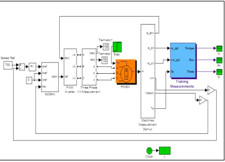
The simulation models of PI speed control of PMSM in MATLAB SIMULINK presented in figures 5-8, where figure 5 is the block diagram of training system and figure 7 is the block diagram with ANFIS estimation system. The GUI ANFIS editor is shown in figure 6.
Torque, flux and rotor position samples are taken from the training system by sampling rate of 10 kHz according to the instantaneous values for stator currents and voltages. The training samples are taken about 2400 points, and the torque reference values are 1 Nm, 2 Nm and 3 Nm as shown in figure 6. The system is run at reference speed of 700 rpm. The three-phase voltage and current (vabc and iabc) are transformed to dq values by using park transformation.
Figure 6 shows the GUI performed Loading, plotting, and clearing the data. Before the training is run, the initial FIS structure and generation parameters should be determined. During the training and generation the FIS file, the error value can be observed. The validating (testing) of the Trained FIS can be achieved by the GUI itself. The fis files are generated and saved to be used in the ANFIS subsystem.
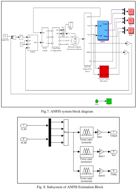
Figure 7 is the estimation system of the torque, flux and theta by using ANFIS subsystem. The reference torque is step from 0.5nm to 1.5nm. Each variable has two values (actual and estimated). The subsystem of ANFIS block shown in figure 8 consists of three fuzzy blocks that fed from three FIS files generated from training system.
Fig.5. training system block diagram
In other words, the same technique is applied to the PMSM with DTC drive as shown in figure 9. The block diagram for the DTC with ANFIS estimation is not only to estimate the torque, speed, flux, and theta but also is applied to estimate the switching table itself, while the load is adjusted to be pulsating load.
Fig.7. ANFIS system block diagram
3 Theta
2 flux
1 Torque Mux
-K-Gain2 -K-Gain1
-K-Gain
Fuzzy Logic Controller2 Fuzzy Logic
Controller1 Fuzzy Logic
Controller 2
vs_qd 1 is_qd
Fig. 8. Subsystem of ANFIS Estimation Block
C) SIMULINK Results
1- Torque Estimation
Figure 10 shows that the estimated motor torque ripples of the block diagram in figure 7 are approximately identical to the actual values with an error of 0.005%, and with no phase shift. From figure 11-a it is seen that the estimated motor flux fluctuates between 19 wb and 21wb and the actual value fluctuates between 20 wb and 21 with error value 0.09 % in magnitude with no phase shift.
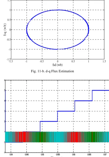
The filterization of training data (extreme data removal) leads to more accurate estimation values. Figure11-b shows the d-q stator flux representation for PMSM at light load.
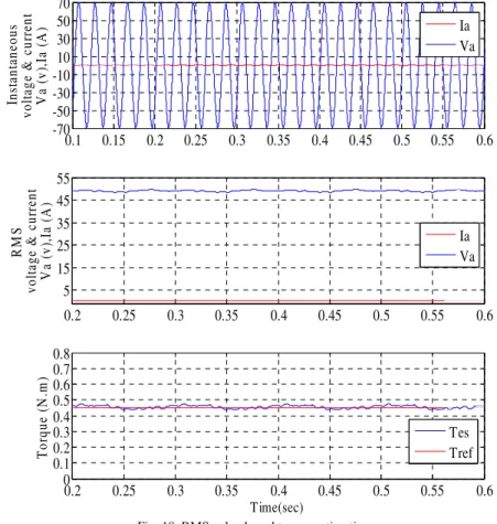
Figure 12 shows the estimated switching table during the six sectors of the motor revolution. It shows the 3 phase inverter switching for each of them throughout the 6 segments (blue). It is clear that every phase switching is shifted from the other by 120 degrees.
0.1 0.12 0.14 0.16 0.18 0.2 0.22 0.24 0.26 0.28 0.3
-1.5 -0.5 0.5 1.5 2.5 3.5
Time (sec)
Tor
q
u
e
(
N
.m
)
Estimated Actual
0.195 0.196 0.197 0.198 0.199 0.2 0.201 0.202 0.203 0.204
-0.5 0 0.5 1 1.5 2 2.5
Time (Sec)
To
rque (
N
.m
)
Estimated Actual
Fig. 10. Torque estimation
Fig. 11-a. flux estimation
0.2 0.201 0.202 0.203 0.204 0.205 0.206 0.207 0.208 5
10 15 20 25
Time (sec)
F
lux (
w
b)
Figure13 represents the motor torque estimation and actual value due to the DTC for pulsating load, the figure shows the torque ripples.
Figure13 shows the ANFIS success in estimating the moment direct control even with the sudden change of torque. Note that the momentum changes from the non-torque up to 1 n.m, the fig. shows the comparison between the real and the predicted torque.
Fig. 11-b. d-q Flux Estimation
-1.5 -1 -0.5 0 0.5 1 1.5
-1.5 -1 -0.5 0 0.5 1 1.5
fsd (wb)
fs
q
(w
b
)
0.54 0.545 0.55 0.555 0.56 0.565 0.57 -1
0 1 2 3 4 5 6
Fig.12. Estimated switching signals per 1 revolution
Sector
Time (sec)
0.8 0.9 1 1.1 1.2 1.3 1.4 1.5 -0.2
0 0.2 0.4 0.6 0.8 1 1.2
Time (Sec)
Torque (N.m)
5. EXPERIMENTAL RESULTS
The system that is used in the experimental results is shown in figure14. The system consists of a PMSM (SMB60) (3000 rpm – 230 V – 1.4 Nm) driven with SLVD2N converter coupled with a 300 w DC separate exited generator that feed variable load (resistance), 3 phase currents and voltages measurement cards, real time microcontroller card to process the training data, and an optional 3 phase to dq conversion cards. Samples of supply voltages and currents that feed the PMSM were taken according to load torque. Instantaneous values (data) of voltages and currents were used to train ANFIS system.
Figure15 shows the 3 phase supply voltages and currents feed the motor, and their conversion to D and Q values to minimize the calculations, especially in real time. These signals have been read through the computer and real time measuring interface devices. Moreover, the figure shows the estimated torque determined through the ANFIS system relying on the incoming signals with an error of 0.05%.
Figure 16 shows the trained system ability to estimate the variable torque. Note that the estimated values (actual) follow up the reference through out the different values.
Fig. 14. Experimental setup
Fig. 15. Voltages, currents and estimated torque
0 0.02 0.04 0.06 0.08 0.1 0.12 0.14 0.16 0.18 0.2
-80 -40 0 40 80
ab
c
vo
lt
age
s (
v
)
0 0.02 0.04 0.06 0.08 0.1 0.12 0.14 0.16 0.18 0.2
-0.5 0 0.5
ab
c
cu
rren
ts (A
)
0 0.02 0.04 0.06 0.08 0.1 0.12 0.14 0.16 0.18 0.2
-80 -40 0 40 80
dq
vo
lt
age
s (
v
)
0 0.02 0.04 0.06 0.08 0.1 0.12 0.14 0.16 0.18 0.2
-0.5 0 0.5
dq
cu
rren
ts (A
)
0 0.02 0.04 0.06 0.08 0.1 0.12 0.14 0.16 0.18 0.2
0.399 0.4 0.401
Time(sec)
T
o
rq
u
e (N
.m
)
Va Vb Vc
Ia Ib Ic
Vd Vq
Id Iq
Figure 17 shows how to track the estimated torque to the resource signals transformed to D and Q. It is clear that the signals can be transferred directly by analog cards from 3 phases to 2 phases. This case is characterized by being rapid in converting the signal immediately to deal with it.
The ANFIS system has estimated the points that have not been trained by the system, even though the system didn't train upon it with a high degree of accuracy. However, the estimated torque follows up the reference torque with error doesn't exceed 0.1%.
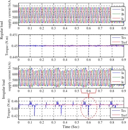
Figure18 shows the reliability of using the RMS value instead of the instantaneous value to estimate the torque that reduce the time of calculations, by experiment, it is shown that this method is preferred at high speed and it is characterized by being very cheap as we do not need to measure the instantaneous values. Inverter switching affects on the shape of the output voltages and currents. So, the ANFIS technique was applied to the switched voltages and currents.
Figure 19 shows the slight switching effect in estimating the torque where compared to existing ripples the direct torque control is relatively low. Figure 20 shows the possibility to estimate the torque by the current training only. In this case the estimation error is lower in comparison with currents and voltages training. It shows that the mechanical or loading fault diagnosis of the motor, such as misalignments between motor and load, or load vibration or any other problems. The figure compare between estimated torque at the healthy (regular) load and the other at faulted (irregular) load.
Fig. 16. Variable torque estimation
0 0.1 0.2 0.3 0.4 0.5 0.6 0.7
-0.2 0 0.2 0.4 0.6
Time (sec)
T
or
que
(
N
.m
)
Actual Ref
Fig. 17. Non-Trained data torque estimation
0 0.01 0.02 0.03 0.04 0.05 0.06 0.07 -75
-50 -25 0 25 50 75
Time(sec)
d
q
su
p
p
ly
v
o
lt
ag
es &
cu
rr
en
ts
V
sd
q
(v
),
Is
d
q
(A
)
0 0.01 0.02 0.03 0.04 0.05 0.06 0.07 0.2
0.3 0.4 0.5
Time(sec)
T
o
rq
u
e(N
.m
)
Tes Tref
0 0.02 0.04 0.06 0.08 0.1 0.12 0.14 0.16 0.18 0.2 400 500 600 700 Time(sec) Va ( v )
0 0.02 0.04 0.06 0.08 0.1 0.12 0.14 0.16 0.18 0.2
400 500 600 700 Time(sec) Ia ( A )
0 0.02 0.04 0.06 0.08 0.1 0.12 0.14 0.16 0.18 0.2
0.2496 0.2498 0.25 0.2502 Time(sec) To rq u e( N .m )
Fig. 19. switching effect on torque estimation Note: the voltage and current values are ADC output data
Phase voltage
P
h
ase curr
ent
Fig. 18. RMS value based torque estimation
0.1 0.15 0.2 0.25 0.3 0.35 0.4 0.45 0.5 0.55 0.6 -70 -50 -30 -10 10 30 50 70 I ns ta nt an eous v o lt age & c ur re nt V a (v ), Ia (A )
0.2 0.25 0.3 0.35 0.4 0.45 0.5 0.55 0.6 5 15 25 35 45 55 RM S vol ta ge & c ur re nt V a (v ), Ia (A )
The speed estimation is not difficult to the ANFIS where this technique make the DTC can abandon the resolver or speed encoder. Figure 21 shows the ability of speed estimation depending on the RMS voltage only. Figure 21-b shows the speed change according to the same values of the voltage training data, where figure 21-c shows the speed change according to the new values of voltage values.
Fig. 20. Current based torque estimation
0 0.1 0.2 0.3 0.4 0.5 0.6 0.7 0.8 0.9
400 500 600 700 su p p ly c u rre n t Is (A
0 0.1 0.2 0.3 0.4 0.5 0.6 0.7 0.8 0.9
0.449 0.45 0.451 T o rq u e (N .m )
0 0.1 0.2 0.3 0.4 0.5 0.6 0.7 0.8 0.9
400 500 600 700 su pp ly cur rent I s( A )
0 0.1 0.2 0.3 0.4 0.5 0.6 0.7 0.8 0.9
0.42 0.44 0.46 Time (Sec) T o rq u e (N .m ) Ia Ib Ic Ia Ib Ic Tes Tref Tes Tref
Note: the lower currents and torque diagrams are for irregular load Note: the current values are ADC output data
Regular load Irreg u lar lo ad
0 0.04 0.08 0.12 0.16 0.2 0.24 0.28 0.3 500 600 700 800 900 1000 Time (Sec) M o to r S p eed ( rp m ) Actual Estimated
0 0.04 0.08 0.12 0.16 0.2 0.24 0.28 0.3
20 25 30 35 Time (sec) Su pp ly V o lt ag e ( R M S )
0 0.04 0.08 0.12 0.16 0.2 0.24 0.28 0.3
500 600 700 800 900 1000 Time (sec) M o to r Spe ed ( rpm ) Actual Estimated
Fig. 21. Variable speed estimation (a)
(b)
6. CONCLUSION
The Standard DTC with on-off current limit scheme is a fast and effective way to control electric torque and flux in a PMSM machine. Nevertheless, if no modulation on the vectors selected by the commutation table is used, its behavior is rather bang-bang like, producing prominent ripple on the generated torque and stator currents. The estimation problems of torque, flux and position are the main contribution of this paper .This paper found intelligent, accurate and easy way to solve the problems.
In the simulation part, it is proved that the sensor-based system can be converted to sensorless system depending on ANFIS training technique. This technique is not only used for the estimation of torque, speed, position, and flux, but also it can estimate the switching table of the DTC. In addition, it solves the conventional estimation problems used with a direct torque control such as the drift problem; it does not rely on parameters of the machine whatever its type is. Accordingly, ANFIS is suitable for linear and nonlinear systems. The experimental results assure that the ANFIS is perfect estimator in different forms.
Only what is needed the well training and the perfect data (filtered) to give a low error rate. Therefore it is considered to be a low-cost/devices technique.
This technique is tested on the space vector and on the induction motor as well and found to be effective. It is preferable to reduce the transformation calculations equations from 3 phases to 2 phases by using analog electronic circuits to ensure the micro-controller speed and unload it for the expectation process only.
The microcontroller have been used, even though, real time compatible, other new generations of microcontroller could be used specially that are fast and MATLAB interface compatible.
7. REFERENCES
[1] Takahashi and T. Noguchi, “A new quick-response and high-efficiencycontrol strategy of an induction motor,” IEEE Trans. Ind. Applicat., vol. 22, no. 5, pp. 820–827, Sept./Oct. 1986.
[2] Laurent, J., Jabbar, M. A.,Qinghua, L., “Optimization of the Constant Power Speed Range of a Saturated Permanent-Magnet Synchronous Motor”, IEEE Transactions on Ind. App., Vol.42, No.4, pp. 1024-1030, 2006.
[3] Weizhe Qian, Sanjib K. Panda, Jian-Xin Xu, “Torque Ripple Minimization in PM Synchronous Motors Using Iterative Learning Control”, IEEE Transactions on power electronics, vol. 19, 2004, pp272-279.
[4] Romeral Luis, Arias Antoni; Aldabas, Emiliano; Jayne, Marcel G. “Novel direct torque control (DTC) scheme with fuzzy adaptive torque-ripple reduction”; Transactions on Industrial Electronics, vol.50, June, 2003, pp 487-492.
[5] S.Dan, J.G. Zhu,H.Yikang.(2003). Continuous Direct Torque Control of Permanent Magnet Synchronous motor Based on SVM. Zhejiang university, Hangzhoa, China
[6] Y.Yan, J.Zhu, H.Lu . Direct Torque Control of a Surface-Mounted Permanent Magnet Synchronous motor Based on Accurate Modelling. University of Technology, Sydney, Australia.
[7] Khurram, “Position and speed sensorless control of permanent magnet synchronous motors.” Ph.D. dissertation, Michigan State University, East Lansing, MI, 2001.
[8] P. Vas. Vector Control of AC Machines. London, U.K.: Oxford Univ. Press, 1990.
[9] J. Luukko, “Direct torque control of permanent magnet synchronous machines - analysis and implementation.” Ph.D. dissertation, Lappeenranta University of Technology, Lappeenranta , Finland, 2000.
[10] T. Kim, “Sensorless control of the BLDC motors from near-zero to full speed.” Ph.D. dissertation, Texas A&M University, College Station, TX, 2001.
[11] L. Hao, “Permanent magnet AC motor full speed range operation using hybrid sliding mode observer.” Ph.D. dissertation, Texas A&M University, College Station, TX, 2002.
8. BIBLIOGRAPHY