materials
ISSN 1996-1944 www.mdpi.com/journal/materials ArticleAnodization Mechanism on SiC Nanoparticle Reinforced Al
Matrix Composites Produced by Power Metallurgy
Sonia C. Ferreira 1, Ana Conde 2, María A. Arenas 2,*, Luis A. Rocha 3,4 and Alexandre Velhinho 1,5
1 Materials Research Centre/Institute for Nanostructures, Nanomodelling and Nanofabrication (CENIMAT/I3N), Faculdade de Ciências e Tecnologia, FCT, Universidade Nova de Lisboa, 2829-516 Caparica, Portugal; E-Mails: [email protected] (S.C.F.); [email protected] (A.V.) 2 Centro Nacional de Investigaciones Metalúrgicas (CENIM-CSIC), Avda. Gregorio del Amo, 8,
28040 Madrid, Spain; E-Mail: [email protected]
3 Centre for Mechanics and Materials Technologies (CT2M), Research Group on Functionalized Materials and Surfaces Performance, Campus de Azurém, 4810-058 Guimarães, Portugal
4 Departamento de Física, Faculdade de Ciências, Campus de Bauru, Universidade Estadual Paulista “Júlio de Mesquita Filho” (UNESP), Av. Eng. Luiz Edmundo Carrijo Coube, 14-01,
17033-360 Bauru, SP, Brazil; E-Mail: [email protected]
5 Departamento de Ciência dos Materiais (DCM), Faculdade de Ciências e Tecnologia, Universidade Nova de Lisboa, Quinta da Torre, 2829-516 Caparica, Portugal
* Author to whom correspondence should be addressed; E-Mail: [email protected]; Tel.: +34-91-553-8900 (ext. 292); Fax: +34-91-534-7425.
External Editor: Mady Elbahri
Received: 8 October 2014; in revised form: 13 November 2014 / Accepted: 11 December 2014 / Published: 19 December 2014
voltage step increases with the SiCnp volume fraction due to the oxidation of the SiCnp. The formation mechanism of the anodic film on Al/SiCnp composites is different from that occurring in AA1050, partly due the heterogeneous distribution of the reinforcement particles in the metallic matrix, but also to the entrapment of SiCnp in the anodic film.
Keywords: aluminum matrix composite; powder metallurgy; anodizing; oxide film; nanosized reinforcements
1. Introduction
Hard ceramic particle-reinforced aluminum matrix composites (Al-MMCs) have received great interest due to their mechanical and physical properties; as a result, they are widely used to fabricate diverse components for the automotive and aerospace industries [1,2]. Al-MMCs can be reinforced with various oxides, carbides, nitrides and borides, such as SiC, Al2O3, B4C, TiC, TiB2, MgO, TiO2, AlN, BN and Si3N4 [3–7]. The literature is quite extensive on studying the system aluminum matrix reinforced with silicon carbide particles (Al/SiCp), in order to characterize its mechanical [8–10], wear [11,12], corrosion [13,14] and tribocorrosion [15,16] behavior, showing that the fraction volume and/or particle size of SiCp play an important role in the composite behavior.
Powder metallurgy is a solid phase process for the production of particle-reinforced metal matrix composite (MMCs) [17]. Some advantages of solid phase powder metallurgy (PM) compared to casting, such as the improved uniform distribution of the reinforcement within the matrix, minimal solid-state reactions between the metal matrix and the ceramic reinforcement avoiding undesired phases and enhanced bonding between the constituents, have been reported [17–19].
The mechanical properties of the particle-reinforced MMCs are significantly affected by the amount and size of hard ceramic reinforcements [8,9,20]. The SiC nanometric particulate-reinforced Al-MMCs have shown an improvement in the mechanical properties when compared with reinforcement by SiC micrometric ceramic particles [20]. Reinforcement particle size has a strong effect on the failure mode of the MMCs. Large ceramic particles act as micro-concentrators of stress and give rise to cleavage in the particle, leading to failure of the composites [8]. Both tensile strength and ductility decrease with increasing particle size [8,9,20,21]. Similarly, agglomerates of particles degrade the mechanical properties [8,9,20–22], since they cannot transfer shear and tensile stress as a result of the lack of a metal matrix between the reinforcement particles forming the agglomerate [22].
In addition to the mechanical properties, the type of particle-reinforcement, their size and their amount have also a strong influence on Al-MMCs’ corrosion resistance [23–26]. The different electrochemical properties between the metallic matrix and the ceramic reinforcement make MMCs more susceptible to corrosion, and therefore, additional protection is required.
anodic layers on nanoparticle-reinforced Al-MMC using environmentally-friendly procedures, such as tartaric-sulfuric acid (TSA), recently adopted by the European aircraft industry [30–33].
In general, the poor corrosion resistance of the anodic films fabricated on Al/MMC is due to their discontinuity and non-uniform thickness [24,28,29]. He et al. [34] studied the effect of the size of reinforcement particles on the thickness of the anodic layers on Al(2024)/SiC-MMC, showing that the anodic layers are thicker for bigger particles, with an average diameter of 10 µm, but also, they have a lack of uniformity in thickness more remarkable than those fabricated on MMC with SiCp of a smaller diameter, 3.5 µm.
Unlike the mechanical properties, where the use of finer reinforcement particles has demonstrated to enhance the performance of the MMC [8,9,20–22], the influence of the reinforcement nanoparticles on the anodizing process of MMC has been scarcely studied.
In the present work, the anodizing process in tartaric-sulfuric acid (TSA) electrolyte has been used to grow anodic oxide layers on Al-MMC reinforced with SiC nanoparticles produced by PM. The influence of different volume fractions of nanosized SiC reinforcement particles on the morphology, composition and thickness of the anodic film grown on Al/SiCnp-MMCs substrates is discussed.
2. Results and Discussion
2.1. Raw Materials Characterization
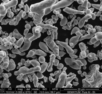
Figure 1 shows the morphology of the as-received Al powders, which exhibit a mixture of cylindrical and spherical shapes. Table 1 gathers the particle size distribution determined by laser diffraction (low angle laser light scattering (LALLS)); the average particle size was 7.70 ± 5.57 µm.
Figure 1. Morphology of as-received Al powders.
distribution: a set of fine particles of 0.07-µm average size and two sets of larger particles (average sizes 0.50 and 2.40 µm, respectively, as individual size or as agglomerates), as shown in Table 1.
Table 2 shows the different composition of the powders after the milling determined by XRF. After 1 h of milling, the unreinforced Al powder shows increased Si and Fe contents [7]. As was expected, when increasing contents of SiC powder were mixed into the Al powder, the overall Si content increased. Moreover, there is also an increase in Fe and Mn due to contamination by the steel balls used during the ball-milling.
Table 1. Particle size distribution of as-received Al and SiC powders.
Powders Average particles size distribution
As-Received Al 7.70 ± 5.57 µm
As-Received SiC 0.07 µm 0.50 µm 2.40 µm
Figure 2. Morphology for the as-received SiC powders.
Table 2. XRF results of the composition of mixture powders (wt%).
Material Al Si Fe Cu Mn Cr
As-received Al 99.60 0.13 0.18 0.01 >0.01 >0.01
60-min milled
Al 99.50 0.20 0.21 0.01 >0.01 >0.01
Al/1 vol% SiCnp 98.00 1.69 0.20 0.01 0.03 >0.01 Al/5 vol% SiCnp 94.50 5.05 0.26 0.03 0.13 >0.01
Al/10 vol% SiCnp 89.80 9.66 0.31 0.02 0.14 0.02
2.2. Microstructure of Al/SiCnp Composites after Sintering
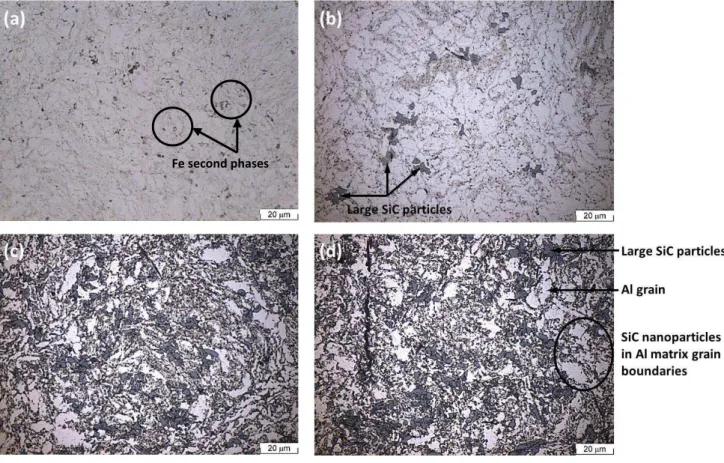
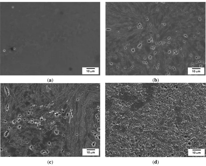
particles. The microstructure of the Al/5 vol% SiCnp and Al/10 vol% SiCnp composite was very similar (Figure 3c,d). Both composites show the typical microstructure of a PM processed material. As can be seen, the reinforcement particulates are distributed in the aluminum matrix, and due to a significant difference between the particle size of the SiC powder and the Al powder (Figures 1 and 2), the SiC nanometric particles tend to fill in the gaps between aluminum powders during powder mixing. Some particles aggregate to form clusters in the Al matrix. This effect is most evident in the composite with higher SiCnp contents (5 and 10 vol%).
Figure 3. Optical micrographs: (a) Unreinforced Al-powder metallurgy (PM) alloy; (b) Al/1 vol% SiCnp; (c) Al/5 vol% SiCnp; (d) Al/10 vol% SiCnp. All of the specimens were etched in a solution of 0.5 vol% hydrofluoric acid (HF) for 30 s.
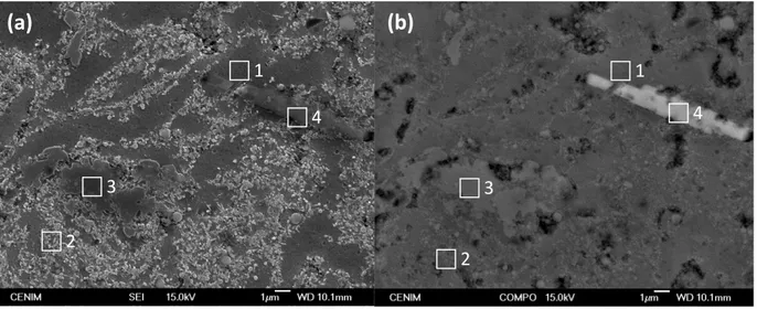
Figure 4 shows the constituent phases of the microstructure of the Al/5 vol% SiCnp in secondary electron imaging (SEI) and in backscattered electron imaging (BEI) mode, respectively. The corresponding chemical compositions are listed in Table 3. The dark grey areas observed in SEI mode (identified by No. 1 in Figure 4a) correspond to the aluminum matrix showing the lowest silicon content. In the same figure, light grey areas (e.g., No. 2) correspond to zones densely reinforced with small SiC nanoparticles. The larger particles, more clearly observed in BEI mode, (No. 3 in Figure 4b), are identified as SiC. Finally, in all of the specimens produced, including the unreinforced Al-PM alloy, the elongated white phases, (No. 4 in Figure 4b), are Fe-rich precipitates resulting from the presence of Fe impurities in the aluminum powder and the erosion of the grinding balls during the fabrication process. These precipitates are Al/Fe intermetallics, the size of which depends on the sintering temperatures [35].
Figure 4. (a) SEI image showing the surface appearance of the Al/5 vol% SiCnp composite etched in 0.5 vol% HF for 30 s; (b) BEI image of the same area. Elemental analysis of the phase constituents is given in Table 3.
Table 3. EDX results at different locations shown in Figure 4 (at%).
at% C O Al Si Mn Fe
Spectrum 1 2.49 3.22 92.64 1.76 – –
Spectrum 2 20.12 10.33 52.02 17.53 – –
Spectrum 3 8.73 7.40 32.90 50.97 – –
Spectrum 4 8.09 13.97 56.29 12.14 0.85 8.65
2.3. Surface Modification of Al/SiCnp by Alkaline Etching and De-Smutting
Before the anodizing process, the specimens were pre-treated in an alkaline bath in sodium hydroxide solution and then de-smutted in nitric acid solution. This is a common pre-treatment used in the aircraft industry for preparing the aluminum alloys surfaces before the anodization. The alkaline treatment promotes the formation of a smut layer composed of oxides, which is subsequently removed by immersion in the acid solution de-smutting. Figure 5a shows the pre-treated surface topography of the Al/5 vol% SiCnp composite. After the pretreatment, the surface reveals a high concentration of SiC particles, as well as some porosity in those areas where particles are concentrated. At higher magnifications, the areas with a lower presence of reinforcement particles (dotted line rectangle of Figure 5a) show a grooved surface, pointing out the composite dissolution during the alkaline etching; Figure 5b. This area is not entirely free of particles, since finer reinforcement particles are distinguished on the surface.
These pre-treated surfaces will be subsequently anodized in TSA. 2
1
4
3
(b)
1
4
2
3
Figure 5. (a) SEM image of the Al/5 vol% SiCnp after alkaline etching and de-smutting; (b) close view of the boxed area.
2.4. Anodizing of Al/SiCnp Composites in TSA Bath
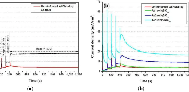
During the anodizing process performed in TSA under controlled voltage conditions, the current density-time response is recorded for a better control of the process. Figure 6a shows the current transients corresponding to unreinforced Al-PM alloy and the commercial AA1050 aluminum alloy. The current density-time responses corresponding to the Al/SiCnp composites are shown in Figure 6b.
All of the current density curves show five stages corresponding to each 4-V step applied. At the beginning of each stage, there is a surge in current, followed by decay towards a steady value. This surge arises from rapid thickening of the anodic oxide in response to the increase of field following the voltage step [36]. Additionally, in the specimens containing SiCnp, a peak is recorded in Stage V at 270 s, approximately, just before the steady state at 20 V is reached.
Figure 6. Comparison of the anodizing current-time responses at 20 V in a TSA bath at 35 °C: (a) unreinforced Al-PM alloy and commercial AA1050; (b) Al/SiCnp composites prepared by PM.
(a) (b)
Porosity
The comparison of the current density-time response corresponding to the unreinforced Al-PM and the commercial AA1050 aluminum alloy reveals significant differences; Figure 6a. The current density achieved at steady state is around 18 mA·cm−2 for AA1050 and 4 mA·cm−2 for unreinforced Al-PM alloy. This result suggests that even though their chemical compositions are similar, the processing method of the aluminum alloys has a remarkably influence on the anodizing process. The residual porosity of the specimens obtained by PM might influence the current density-time responses (see Figure 7). The residual porosity significantly increases the effective area available during the anodizing process, but it also modifies the electrical conductivity of the material.
In fact, the conductivity seems to be the key parameter to explain the different behavior observed between the AA1050 and unreinforced Al-PM alloy. In the commercially pure aluminum alloy, the efficiency of the anodizing process is the highest, since all of the applied charge is mostly used to grow the alumina film. In this sense, the lower current density recorded for the unreinforced Al-PM alloy indicates a lower efficiency of the anodizing process regarding the commercial alloy.
Figure 7. SEM micrographs after alkaline etching and de-smutting for: (a) commercial AA1050; (b) unreinforced Al-PM alloy; (c) Al/1 vol% SiCnp; (d) Al/5 vol% SiCnp; (e) Al/10 vol% SiCnp.
(a) (b)
(c) (d)
10 m 10 m
Figure 7. Cont.
(e)
The current density-time response, Figure 6b, recorded for the unreinforced Al-PM alloy and Al/1 vol% SiCnp have similar features in the five stages. Surges, decays and plateaus of current density are analogous, presenting in Stage V a steady current density of about 4 mA·cm−2.
With the increase of the reinforcement volume fraction of SiCnp in Al composites, the current densities of each stage increase, and the steady state is more difficult to achieve. Moreover, in the Al/10 vol% SiCnp, the curve shows that the current density exhibits a continuous decay until the next voltage step is applied, and the steady state is only reached in the last voltage step (Stage V). The Al/SiCnp composites reinforced with 5 and 10 vol% achieve a steady current density of about 9 and 16.5 mA·cm−2, respectively, at 1200 s. At the beginning of Stage V, after the initial current time surge, the composites reinforced with 5 and 10 vol% clearly reveal a peak that decreases slowly until reaching the steady state. This peak appears related to the presence of higher SiCnp content, suggesting that the higher the content of reinforcement particles, the higher the contribution of the SiCnp, which is being oxidized at the applied voltage. Therefore, the changes observed on the current density vs. time responses suggest that the incorporation of the nanometer SiCp in the alloy varies the formation mechanism and growth rate of the anodic layer regarding the unreinforced Al-PM alloy.
It has to be mentioned that the residual porosity observed on the specimens with 5 and 10 vol% after pre-treatment (Figure 7d,e) also affects the electrical conductivity of these materials and, therefore, the anodizing process. Moreover, Srivastava et al. [36] and Padmavathi et al. [37] found that the electrical conductivity of Al/SiCp decreases with the increase in the volume fraction of the SiCp, not only due to the addition of a phase with lower conductivity than the Al matrix, but also because when high volume fractions of reinforcement particles are present, reinforcement clusters and porosity are often observed to decrease the electrical conductivity of the composite material.
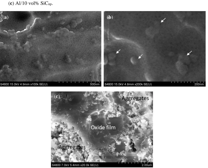
Figure 8a shows the top view of the porous anodic film grown on the Al/5 vol% SiCnp. The average pore diameter ranges between 5 and 15 nm. These values are similar in all of the specimens evaluated in this work. Thus, the pore diameter is not influenced by the reinforcement volume fraction or the processing method of the aluminum alloys. These values are in the same range as those reported in the literature for some aluminum alloys anodized under similar conditions [38,39]. Moreover, the surface of
the 5 vol% SiCnp specimen also shows rounded morphologies of 30–80 nm in diameter that appear to be the SiC particles embedded in the film, as can be observed in Figure 8b (white arrows).
Figure 8. Top-view of the anodic film formed on: (a,b) Al/5 vol% SiCnp; (c) Al/10 vol% SiCnp.
Conversely, when the reinforcement volume fraction increases up to 10 vol% SiCnp the top view of the anodized surface shows great areas of particle aggregates. In these regions, the film is not formed; close to them, there are other areas covered by the anodic film; Figure 8c. Thus, the highest amount of reinforcements in these composites hinders the formation and growth of the film.
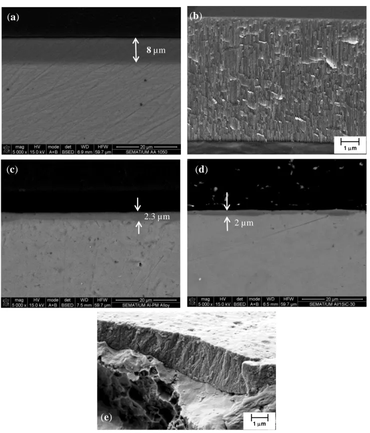
The cross-sections of the anodic layer grown on AA1050, unreinforced Al-PM alloy and Al/1 vol% SiCnp composite are shown in Figure 9. On the AA1050 substrate, a relatively uniform oxide film of 8 µm, approximately, was formed (Figure 9a,b), Additionally in Figure 9b,e the characteristic porous structure growing perpendicularly to the substrate is observed for the oxide layer grown on AA1050 and on 1 vol% SiCnp.
Aggregates
Oxide film
Aggregates
(c)
Figure 9. SEM micrographs of cross-sections of the anodic films formed on: (a,b) AA1050; (c) unreinforced Al-PM alloy; (d,e) Al/1 vol% SiCnp.
Conversely, for unreinforced Al-PM alloy (Figure 9c) and for Al/1 vol% SiCnp (Figure 8d,e), the oxide films are thinner and have a non-uniform thickness. The thickness of the anodic film is about 2.0–3.0 µm for the unreinforced Al-PM alloy and 0.6–2.1 µm for Al/1 vol% SiCnp.
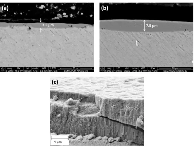
For Al/5 vol% SiCnp, the anodized specimen is much more heterogeneous. The thickness of the anodic film varies from 0.5 to 7.5 µm, depending on the area (Figure 10a,b). This large variation of
1 m
(b)
(a)
8 µm
(c)
2.3 µm
1 m
(e)
2 µm
film thicknesses is due to the heterogeneous distribution of SiCnp in the Al matrix, as was observed in Figure 5a,b). Figure 10a shows dark regions within the cross-section, the size of which is much higher than the SiCnp. This suggests that, in fact, these morphologies appear to be cavities associated with the partially oxidized SiC nanoparticles/clusters. Several authors [25,40] have demonstrated that the anodic oxidation of silicon particles proceeded at a significantly reduced rate compared with that of the adjacent aluminum matrix. The occlusion of the partly oxidized particle in the film appears to be associated with cavities above the silicon particles, which had sizes and shapes dependent on the particle morphology. The silicon particles oxidize as a result of the O2− ingress under the high field, and the growth of the anodic SiO2 rim around the particle proceeds with oxygen generation, presumably as a result of the semi-conducting nature of the Si-O bond. As a consequence, oxygen gas-filled voids develop above the oxidizing particles. In areas remote from SiC particles, regular porous anodic film develops.
Figure 10. Cross-sections of the anodic films formed on Al/5 vol% SiCnp specimens: (a,b) areas with a non-uniform thickness film; (c) microstructure of the porous anodic layer.
Figure 10c shows the cross-section of the anodic film grown on the Al/5 vol% SiCnp where the characteristic pores perpendicular to the substrate are clearly seen on the anodized specimen.
This work has shown that Al composites reinforced with SiC nanoparticles produced by PM can be anodized, resulting in the growth of a continuous and potentially protective oxide film. Nevertheless, the amount of reinforcing SiCnp should be limited to 5 vol%, avoiding the formation of aggregates in the Al matrix, since there is no film in the areas with high concentration/aggregates of SiCnp.
3. Experimental Section
3.1. Materials
Particle size distributions of raw materials, i.e., as-received pure Al and as-received SiC powders, supplied by Goodfellow (Cambridge, UK), were measured by LALLS method using a Coulter LS 230 (Coulter Electronics, Krefeld, Germany) equipped with the PIDS technique (polarization intensity differential scattering).
The Al/SiCnp composites were produced by a powder metallurgy method and were prepared with different reinforcement volume fractions, namely 1, 5 and 10 vol%. For comparison purposes, an unreinforced Al-PM alloy specimen was also produced. Proper proportions of the powders were placed in a high-energy ball mill for 60 min, together with 5 mm diameter AISI (American Iron Steel Institute) 52100 steel balls. The total powder mass was 11 g, the ball to powder weight ratio being 2:1. Acetone was used as a process control agent (0.05 mL·g−1). The milled powders were consolidated by cold pressing at 200 MPa for 1 min into bulk specimens of 30 mm in diameter.
The chemical composition of the green compact specimens was measured using a Philips Analytical sequential X-ray fluorescence (XRF) spectrometer Model X’Unique II (Philips, Amsterdam, The Netherlands). In the sintering step, the green compact specimens are placed on a high-vacuum atmosphere furnace at 650 °C for 1 h, with a heating rate of 4 °C min−1.
3.2. Metallographic Preparation and SEM Analysis
The sintered specimens were ground to 1200 grit emery paper and polished to a 1-µm diamond suspension. In order to identify any second phases present, the specimens were etched by 0.5 vol% hydrofluoric acid (HF) for 30 s.
The morphology of the specimens was investigated using an optical microscope (OM) and scanning electron microscopes with energy dispersive X-ray (EDX): a JEOL 6500F (Musashino 3-chomeAkishima, Tokyo, Japan), a Hitachi S-4800 (Hitachi, Chiyoda-Ku, Tokyo, Japan), a NanoSEM-FEI Nova 200 (FEG/SEM, Nova, Hillsboro, OR, USA) and a ZEISS Auriga CrossBeam workstation (Carl Zeiss Microscopy GmbH, Jena, Germany).
3.3. Pretreatment and Anodizing Surface Treatment
The pretreatment process of the specimen prior to anodizing comprised the following steps: degreasing in ethanol, alkaline etching for 30 s in 0.5 M NaOH solution at 40 °C and de-smutting for 15 s in a 7.2 M nitric acid solution at room temperature. After each step, the specimens were gently rinsed with distilled water and dried.
60 s were applied up to a final value of 20 V, which was then maintained constant for 1200 s until completion of the anodizing process. A platinum mesh was used as a cathode. After anodizing, the specimens were immediately immersed for 10 min in deionized water at room temperature to remove any acid within the porous layer, then finally dried.
For comparison purposes, a commercial electropolished AA1050 sheet (minimum of 99.5% Al, with Fe < 0.30% and Si < 0.20% as principal alloying elements) was pre-treated and anodized under the same conditions as Al/SiCnp composites.
4. Conclusions
Specimens of unreinforced Al-PM alloy and nanosized Al/SiCp composites produced by PM were anodized in tartaric-sulfuric acid at 20 V to study the ability of this surface treatment to fabricate homogeneous anodic films with potential protective properties for the SiCnp-reinforced Al-MMCs. The current density versus time response reveals that the SiCnp reinforcement volume fraction
influences the anodizing mechanism.
The increasing content of nanosized SiC particles in Al composites induces a rise of the current density values due to the partial oxidation of the SiCnp. These particles are finally occluded in the film due to the preferential oxidation of the surrounding Al matrix. The presence of gas-filled voids throughout the cross-section of the anodizing film reveals the uniform entrapment of the SiCnp within the anodic film.
SiC particles in the nanoscale range and with contents of about 1% and 5% decrease the efficiency of the anodizing process and hinder the film formation, but still, a continuous anodic oxide layer covers the surface; conversely, if the content is too high (10%), particles agglomerate, shielding the matrix, and the film is not formed.
Acknowledgments
Sonia Cristina Ferreira and Alexandre Velhinho would like to acknowledge Portuguese Science and Technology Foundation/Portuguese Ministry for Science, Technology and Higher Education for funding granted to Materials Research Centre/Institute for Nanostructures, Nanomodelling and Nanofabrication under Strategic Project on Materials Science and Technology (Strategic Project-LA25-2013-2014). Sonia Cristina Ferreira would also like to acknowledge FCT for funding Ph.D. Grant SFRH/BD/28474/2006. Ana Conde and María Ángeles Arenas acknowledge to the Spanish Ministry of Science and Innovation under Consolider-Ingenio 2010 CSD 2008-0023 FUNCOAT Project.
Author Contributions
Conflicts of Interest
The authors declare no conflict of interest.
References
1. Chawla, N.; Chawla, K.K. Metal-matrix composites in ground transportation. JOM 2006, 58, 67–70.
2. Abdoli, H.; Saebnouri, E.; Sadrnezhaad, S.K.; Ghanbari, M.; Shahrabi, T. Processing and surface properties of Al–AlN composites produced from nanostructured milled powders. J. Alloy. Compd. 2010, 490, 624–630.
3. Toptan, F.; Kilicarslan, A.; Karaaslan, A.; Cigdem, M.; Kerti, I. Processing and microstructural characterisation of AA 1070 and AA 6063 matrix B4Cp reinforced composites. Mater. Des. 2010, 31, S87–S91.
4. Lee, K.B.; Ahn, J.P.; Kwon, H. Characteristics of AA 6061/BN composite fabricated by pressureless infiltration technique. Metall. Mater. Trans. A 2001, 32A, 1007–1018.
5. Ipek, R. Adhesive wear behaviour of B4C and SiC reinforced 4147 Al matrix composites (Al/B4C–Al/SiC). J. Mater. Process. Technol. 2005, 162–163, 71–75.
6. Abenojar, J.; Martinez, M.A.; Velasco, F. Effect of the boron content in the aluminium/boron composite. J. Alloy. Compd. 2006, 422, 67–72.
7. Abenojar, J.; Velasco, F.; Martinez, M.A. Optimization of processing parameters for the Al + 10%B4C system obtained by mechanical alloying. J. Mater. Process. Technol. 2007, 184, 441–446. 8. Kang, Y.C.; Chan, S.L.I. Tensile properties of nanometric Al2O3 particulate-reinforced aluminum
matrix composites. Mater. Chem. Phys. 2004, 85, 438–443.
9. Ma, Z.Y.; Li, Y.L.; Liang, Y.; Zheng, F.; Bi, J.; Tjong, S.C. Nanometric Si3N4 particulate-reinforced aluminum composite. Mater. Sci. Eng. A 1996, 219, 229–231.
10. Hong, S.J.; Kim, H.M.; Huh, D.; Suryanarayana, C.; Chunin, B.S. Effect of clustering on the mechanical properties of SiC particulate-reinforced aluminum alloy 2024 metal matrix composites. Mater. Sci. Eng. A 2003, 347, 198–204.
11. Veeresh Kumar, G.B.; Rao, C.S.P.; Selvaraj, N. Studies on mechanical and dry sliding wear of Al6061–SiC composites. Compos. Part B Eng. 2012, 43, 1185–1191.
12. Vieira, A.C.; Sequeira, P.D.; Gomes, J.R.; Rocha, L.A. Dry sliding wear of Al alloy/SiCp functionally graded composites: Influence of processing conditions. Wear 2009, 267, 585–592. 13. Singh, I.B.; Mondal, D.P.; Singh, M.; Das, S. Influence of SiC particle addition on the corrosion
behaviour of 2014 Al-Cu alloy in 3.5% NaCl solution. Corros. Sci. 2009, 51, 234–241.
14. Pardo, A.; Merino, M.C.; Merino, S.; Viejo, F.; Carboneras, M.; Arrabal, R. Influence of the reinforcement proportion and matrix composition on pitting corrosion behaviour of cast aluminium matrix composites (A3xx.x/SiCp). Corros. Sci. 2005, 47, 1750–1764.
16. Vieira, A.C.; Rocha, L.A.; Mischler, S. Influence of SiC reinforcement particles on the tribocorrosion behaviour of Al–SiCp FGMs in 0.05 M NaCl solution. J. Phys. D Appl. Phys. 2011, 44, 185301–185309.
17. Torralba, J.M.; Costa, C.E.; Valasco, F. P/M aluminum matrix composites: An overview. J. Mater. Process. Technol. 2003, 133, 203–206.
18. Wang, H.; Zhang, R.; Hu, X.; Wang, C.; Huang, Y. Characterization of a powder metallurgy SiC/Cu–Al composite. J. Mater. Process. Technol. 2008, 197, 43–48.
19. El-Eskandarany, M.S. Mechanical solid state mixing for synthesizing of SiCp/Al nanocomposites. J. Alloy. Compd. 1998, 279, 263–271.
20. Tjong, S.C. Novel nanoparticle-reinforced metal matrix composites with enhanced mechanical properties. Adv. Eng. Mater. 2007, 9, 639–652.
21. Rahimian, M.; Ehsani, N.; Parvin, N.; Baharvandi, H.R. The effect of particle size, sintering temperature and sintering time on the properties of Al–Al2O3 composites, made by powder metallurgy. J. Mater. Process. Technol. 2009, 209, 5387–5393.
22. Sivasankaran, S.; Sivaprasad, K.; Narayanasamy, R.; Iyer, V.K. Synthesis, structure and sinterability of 6061 AA100−x−x wt.% TiO2 composites prepared by high-energy ball milling. J. Alloy. Compd. 2010, 491, 712–721.
23. Shahid, M. Mechanism of film growth during anodizing of Al-alloy-8090/SiC metal matrix composite in sulphuric acid electrolyte. J. Mater. Sci. 1997, 32, 3775–3781.
24. He, C.; Liu, C.; Li, F.; Cai, Q.; Shi, Z.; Chen, L.; Bi, J. Corrosion behaviour and protection efficiency of 2024Al and SiCp 2024Al metal matrix composite. J. Mater. Sci. Technol. 2002, 18, 351–353.
25. He, C.; Lou, D.; Wang, J.; Cai, Q. Corrosion protection and formation mechanism of anodic coating on SiCp/AL metal martrix composite. Thin Solid Films 2011, 519, 4759–4764.
26. Picas, J.A.; Martín, E.; Baile, M.T.; Rupérez, E.; Forn, A. Hard anodizing of aluminium matrix composite A6061/(Al2O3)p for wear and corrosion resistance improvement. Plasma Process. Polym. 2007, 4, S579–S583.
27. Wernick, S.; Pinner, R.; Sheasby, P.G. The Surface Treatment and Finishing of Aluminium and Its Alloys, 6th ed.; ASM International Finishing Publications Ltd.: Herts, UK, 2001; Volume 1. 28. Lin, S.; Greene, H.; Shih, H.; Mansfeld, F. Corrosion protection of Al/SiC metal matrix composites
by anodizing. Corrosion 1992, 48, 61–67.
29. Hou, J.; Chung, D.D.L. Corrosion protection of aluminum-matrix aluminum nitride and silicon carbide composites by anodization. J. Mater. Sci. 1997, 32, 3113–3121.
30. Ocón, P.; García-Rubio, M.; Lavía, A.; García, I. Procedure for Anodising Aluminium or Aluminium Alloys. EP 2055 810A2, 29 October 2007.
31. Garcia-Rubio, M.; Ocon, P.; Curioni, M.; Thompson, G.E.; Skeldon, P.; Lavia, A.; Garcia, I. Degradation of the corrosion resistance of anodic oxide films through immersion in the anodising electrolyte. Corros. Sci. 2010, 52, 2219–2227.
33. Arenas, M.A.; Conde, A.; de Damborenea, J.J. Effect of acid traces on hydrothermal sealing of anodising layers on 2024 aluminium alloy. Electrochim. Acta 2010, 55, 8704–8708.
34. He, C.; Zhou, Q.; Liu, J.; Li, F.; Geng, X.; Cai, Q. Effect of size of reinforcement on thickness of anodized coatings on SiC/Al matrix composites. Mater. Lett. 2008, 66, 2441–2443.
35. Abenojar, J.; Velasco, F.; Martinez, M.A. Differential thermal analysis of the Al + 20% (Fe–50%B) system. J. Solid State Chem. 2006, 179, 2787–2790.
36. Srivastava, V.C.; Ojha, N. Microstructure and electrical conductivity of Al-SiCp composites produced by spray forming process. Bull. Mater. Sci. 2005, 28, 125–130.
37. Padmavathi, C.; Upadhyaya, A. Densification, microstructure and properties of supersolidus liquid phase sintered 6711Al-SiC metal matrix composites. Sci. Sinter. 2010, 42, 363–382.
38. Bartolomé, M.J.; Lopez, V.; Escudero, E.; Caruana, G.; Gonzalez, J.A. Changes in the specific surface area of porous aluminium oxide films during sealing. Surf. Coat. Technol. 2006, 200, 4530–4537.
39. Boisier, G.; Pébère, N.; Druez, C.; Villatine, M.; Suel, S. FESEM and EIS study of sealed AA2024 T3 anodized in sulfuric acid electrolytes: Influence of tartaric acid. J. Electrochem. Soc. 2008, 155, C521–C529.
40. Fratila-Apachitei, L.E.; Tichelaar, F.D.; Thompson, G.E.; Terryn, H.; Skeldon, P.; Duszczyk, J.; Katgerman, L. A transmission electron microscopy study of hard anodic oxide layers on AlSi(Cu) alloys. Electrochim. Acta 2004, 49, 3169–3177.