INFLUENCE OF E-GLASS AND
GRAPHITE PARTCLE ON AL-356
ALLOY COMPOSITE PRODUCED BY
VORTEX METHOD
K.ANNAMALAI *Professor, School of Mechanical & Building Sciences (SMBS), VIT University, Vellore - 632014, Tamil Nadu, India
RAMANGOUDA PATIL**, ARJUN C C, VENUGOPAL PILLARISETTI
SMBS, VIT University, Vellore - 632014, Tamil Nadu, India
Abstract
Aluminium hybrid composites have been under analytical and experimental investigation for decades in the context of aerospace, marine and mechanical applications. Of late, the use of aluminum hybrid composites in civil engineering applications is steadily increasing. The objective of this work is to characterize and quantify the properties of hybridized aluminium reinforced composites. Different configurations of aluminium E-glass and graphite particles are manufactured using vortex method and subjected to heat treatment where the residual stresses are relieved. Specimens of composite with 1.25% & 2.5% of both E-glass fibers and graphite particles by weight are prepared for macrostructure and microstructure study to understand the distribution of reinforcements. Further these specimens are subjected to experiments to identify the mechanical behavior. The plots of properties bring out a composition in which, a composite of 1.25% & 2.5% of both E-glass fibers and graphite particles by weight show satisfactory results when compared to Al-356 alloy.
Key words: Aluminium, Hybrid Composite, E-glass, Graphite, Vortex Method.
1. Introduction
Many of our modern technologies require materials with special properties that cannot be met by the conventional metal alloys, ceramics and polymeric materials. This is especially true for materials that are needed for aerospace, automobile and underwater applications. For example, aircraft engineers are increasingly searching for structural materials that have low densities, higher strength, better stiffness, increased abrasion and impact resistance and having improved corrosion resistance which is a rather formidable combination of characteristics. Strong materials are relatively denser than composites, increasing their strength or stiffness generally results in decrease in impact strength. Therefore when an application exists where no single material exhibits all the desired properties, different materials comprising the desired properties are combined to meet the requirements, and the resulting material is called composite.
A composite is a multi-phase material that is artificially made, as opposed to the one that occurs or forms naturally. For example, bone is a composite of the strong yet soft protein collagen and the hard, brittle mineral apatite. Composites have been developed with great success by the use of constituent phases, which are chemically dissimilar and separated by a distinct inter-phase. Thus, most metallic alloys and ceramics do not fit into this definition of composites because of their multiple phases formed as consequences of natural phenomena. Generally, composite materials are composed of two phases; first one is termed the matrix, which is continuous and surrounds the second phase, often known as the dispersed phase. Newly evolved reinforced composites are the hybrid composites, which are obtained by using two or more different kinds of reinforcement in a single matrix. Hybrid composites have better all round combination of properties than composites containing only a single reinforcement [Deteresa et al (1998)]
large and increasing number of commercial mechanical engineering applications, such as internal combustion engines, machine components, thermal control and electronic packaging, automobiles and mechanical components such as brakes, drive shafts, flywheels, tanks and pressure vessels [Surappa M K, (2003)].
2. Need for Aluminium Composites
Aluminum is a versatile metal, which has tremendous usage in the realm of industries and other spheres of life. Aluminum oxide, which is an alloy of aluminum, forms a protective layer over the aluminum saving it from further wear and tear. Aluminum has vast usage in the water treatment industry. For water treatment, aluminum sulphate is prepared using aluminum hydroxide which is used in water treatment plants and paper industries. In recent past, drink cans are being made from aluminum and several steps are being undertaken to recycle these cans. Aluminium is also used as foils, which keep food warm and protected. Foils can be used to wrap up rooms in winter to keep them warm.
Although aluminum has a lot of applications and is renowned as a versatile metal, there are certain specific properties which are absent in the native form of aluminum. In order to tap these distinct properties, constant efforts have been put in for the development of a material which would answer to the need of the day. The designers enjoy the freedom of using aluminum composites for the fact that the structural properties of these can be varied throughout the design in order to address key constraints and hence minimize the overall cost of the material unlike that in the case of conventional practices.
3. Processing Methods of Composites
Primary processes for manufacturing of Aluminium Matrix Composites (AMC) in industrial scale can be classified into two main groups, Solid State Processes and Liquid State Processes. Solid State Processes include powder blending followed by consolidation of the blend, diffusion bonding and vapour deposition techniques. Liquid State Processes include stir casting or compo casting, infiltration, spray casting, vortex method (stir casting method) and in-situ (reactive) processing. The selection of the processing route depends on many factors including type and level of reinforcement loading and the degree of micro-structural intensity desired. It is possible to manufacture AMC of specific formulation (having the same matrix and reinforcement combination) by more than one route.
The Vortex method is one of the simplest processing methods and the quality of the casting obtained is also superior. Hybrid AMCs using Aluminium alloy AL-356 reinforced with E-glass fibers and Graphite particles using stir-cast method are studied in this work. The base metal matrix containing different percentages of reinforcements are produced by this process. Furthermore, hybrid AMCs produced are characterized by different tests such as hardness, compression, wear and micro-structural studies.
4. Material Used in Processing of Aluminium Hybrid Composites
4.1. Aluminium alloy (AL-356)
Aluminium alloy (AL-356 or LM-25) alloy conforms to BS 1490:1988. Castings are standardized in the cast (M) condition, the precipitation treated (TE) condition, the solution treated and stabilized (TB7) condition and the fully heat treated (TF) condition [Brown John R handbook].
4.1.1 Mechanical properties
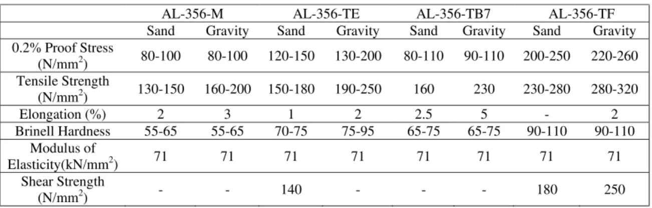
Table 1. Mechanical Properties
AL-356-M AL-356-TE AL-356-TB7 AL-356-TF
Sand Gravity Sand Gravity Sand Gravity Sand Gravity
0.2% Proof Stress
(N/mm2) 80-100 80-100 120-150 130-200 80-110 90-110 200-250 220-260
Tensile Strength
(N/mm2) 130-150 160-200 150-180 190-250 160 230 230-280 280-320
Elongation (%) 2 3 1 2 2.5 5 - 2
Brinell Hardness 55-65 55-65 70-75 75-95 65-75 65-75 90-110 90-110
Modulus of
Elasticity(kN/mm2) 71 71 71 71 71 71 71 71
Shear Strength
AL-356 has good strength at elevated temperatures and possesses good machinability characteristics with corrosive resistance.
5. Reinforcements Used
5.1 Graphite particles (Gp)
Graphite is one of the three allotropic forms of carbon the other two being coal and diamond. It crystallizes in hexagonal system but it is rare to find perfect crystals of graphite. The size of the graphite particles used in this study is 20-120 micrometers.
5.2 E-Glass fibers (Ef)
E-Glass or Electrical Grade glass was originally developed for standoff insulators for electrical wiring. It was later found to have excellent fiber forming capabilities and is now used almost exclusively as the reinforcing phase in the material commonly known as fiber glass and also in composites.
5.2.1 Composition of E-glass
E-Glass is a low alkali glass with a typical nominal composition of SiO2 - 54wt%, Al2O3 - 14wt%, CaO
+ MgO - 22wt%, B2O3 - 10wt% and Na2O + K2O are less then 2wt%. Some other materials may also be present
at impurity levels.
6. Processing of Aluminium Hybrid Composites
6.1 Production of casting
The production of casting involves the following steps:
Melting of alloy.
Degassing.
Stirring (creating a vortex) and simultaneous addition of reinforcements.
Pouring of the molten mixture in moulds
6.1.1 Melting of alloy
The ingots of aluminium alloy (AL-356) are accurately weighed and are taken in a graphite crucible. The crucible is placed in a 3-Phase electrical resistance furnace. The pouring temperature of AL-356 is about 710° C but the maximum temperature is set to 810°C for better pouring results.
Fig. 1. Melting and Degassing
6.1.2 Degassing
0.5 % by weight of molten metal is used for removing the gases from the metal. It is dipped inside the molten metal and the following reaction takes place
C2Cl6 + 2 Al 2 AlCl (slag) + 2 Cl2 (gas) + 2 C (particles)
The chlorine gas which is released starts moving to the top of the molten metal in the crucible. Chlorine gas absorbs hydrogen and other gases into it which results in gas free molten metal. [Brown John R handbook]
6.1.3 Stirring (Creating a Vortex) and simultaneous addition of reinforcements
The molten metal which is in the crucible is stirred continuously which creates a vortex [Ejiofor J.U. and Reddy R.G. (1997)]. In the vortex, low pressure region is created and preheated mixture of reinforcements (fibers + particulates) is added slowly. Due to the agitation of the molten metal, reinforcements takes place, hence forming a homogeneous mixture.
Fig. 2. Vortex Method setup and Pouring
6.1.4 Pouring of molten mixture in moulds
Cast iron moulds of diameter 60mm and height 175mm are used. After a few minutes of stirring, the molten metal with reinforcements is transferred into metallic moulds and allowed to solidify. After cooling, the casting is taken out.
6.2 Heat treatment
Heat treatment is done for changing the mechanical properties, the metallurgical structure and the residual stress state of a metal. It increases the strength and hardness of the aluminum alloys. It is a three step process:
Solution Heat Treatment: Dissolution of soluble phases.
Quenching: Development of super saturation.
Age Hardening: Precipitation of solute at elevated temperatures (artificial ageing or precipitation heat treatment) [ASM Handbook (2000)]
7. Study of Properties
7.1 Macrostructure
Fig.. 3. Macrostructure of aluminium alloy (AL-356) without reinforcements.
Fig. 4. Macrostructure of aluminium alloy (AL-356) reinforced with 1.25 % of E-Glass fibers and 1.25 % of Graphite particles
Fig. 5. Macrostructure of aluminium alloy (AL-356) reinforced with 2.5 % of E-Glass fibers and 2.5 % of Graphite particles
Table 2. Macrostructure table of the three cases considered
AL-356 + 0% E-Glass Fibers + 0% Graphite Particles
Top Middle Bottom
Distribution _ _ _
Porosity No No No
AL-356 + 1.25% E-Glass Fibers + 1.25% Graphite Particles
Top Middle Bottom
Distribution Evenly Evenly Evenly
Porosity No No No
AL-356 + 2.5% E-Glass Fibers + 2.5% Graphite Particles
Top Middle Bottom
Distribution Less More More
7.2 Metallographic results
Fig. 6. Optical micrographs of the base, aluminium alloy (AL-356) showing aluminium and silicon.
Fig. 7. Optical micrographs of aluminium alloy (Al-356) reinforced with 1.25% of E-glass fibers and 1.25% of graphite particles.
Fig. 8. Optical micrographs of aluminium alloy (Al-356) reinforced with 2.5% of E-glass fibers and 2.5% of Graphite particles.
7.3 Hardness test results
Table 3. Comparison of hardness test of base AL-356 reinforced with 0%Gp + 0%Ef, 1.25% Gp+1.25%Ef and 2.5% Gp +2.5% Ef
Trial No. Specimen
Reading (mm) Average
Diameter (mm) BHN X-Axis Y-Axis 1 2 3 0% 2.841 2.710 2.789 2.839 2.713
2.811 2.784 80
1 2 3
1.25% Gp
+ 1.25% Ef
3.593 3.686 3.819
3.608 3.713
3.793 3.704 45
1 2 3
2.5% Gp
+ 2.5% Ef
2.671 2.844 2.844
2.765 2.810
2.930 2.833 78
Fig. 9. BHN v/s Percentage of reinforcement
The hardness results show that for lesser percentage of reinforcement, the BHN is less. However, for increased percentage of 2.5% each of E-glass fibers and Graphite particles, the BHN has again increased considerably.
7.4 Compression test results
Test specimen dimensions: Length – 15.00mm; Diameter – 11.25mm; Cross section area – 99.40mm2
Table 4. Tabular column of compression test for 0% of E-Glass fiber and graphite particles.
Sl.No. Decrease in Length
Load (kg) Load, F (N) Stress (MPa)
Strain
1 0.25 2740 26879.4 270.89 0.016
2 0.50 3140 30803.4 310.44 0.032
3 0.75 3360 32961.6 332.19 0.049
4 1.00 3520 34531.2 348.01 0.065
5 1.25 3670 36002.7 362.84 0.082
6 1.50 3780 37081.8 373.71 0.098
7 1.75 3890 38160.9 384.59 0.114
8 2.00 3990 39141.9 394.48 0.131
9 2.25 4080 40024.8 403.37 0.147
10 2.50 4170 40907.7 412.27 0.163
11 2.75 4250 41692.5 420.18 0.179
12 3.00 4350 42673.5 430.07 0.196
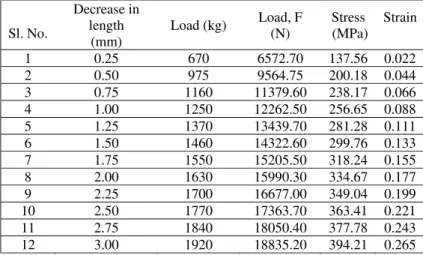
Fig. 11. Stress-Strain curve for Al-356 reinforced with 1.25% E-Glass Fiber + 1.25% Graphite Particles.
Table 5. Tabular column of compression test for Al-356 reinforced with 1.25% E-Glass fiber + 1.25% graphite particles.
Sl. No.
Decrease in length
(mm)
Load (kg) Load, F (N)
Stress (MPa)
Strain
1 0.25 670 6572.70 137.56 0.022
2 0.50 975 9564.75 200.18 0.044
3 0.75 1160 11379.60 238.17 0.066
4 1.00 1250 12262.50 256.65 0.088
5 1.25 1370 13439.70 281.28 0.111
6 1.50 1460 14322.60 299.76 0.133
7 1.75 1550 15205.50 318.24 0.155
8 2.00 1630 15990.30 334.67 0.177
9 2.25 1700 16677.00 349.04 0.199
10 2.50 1770 17363.70 363.41 0.221
11 2.75 1840 18050.40 377.78 0.243
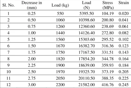
Fig. 12. Stress-Strain curve for Al-356 reinforced with 2.5% E-Glass fiber + 2.5% graphite particles
Table 6. Tabular column of compression test for Al-356 reinforced with 2.5% E-Glass fiber + 2.5% graphite particles.
Sl. No. Decrease in
(mm) Load (kg)
Load (N)
Stress (MPa)
Strain
1 0.25 550 5395.50 104.19 0.020
2 0.50 1060 10398.60 200.80 0.041
3 0.75 1260 12360.60 238.69 0.061
4 1.00 1440 14126.40 272.80 0.082
5 1.25 1560 15303.60 295.52 0.102
6 1.50 1670 16382.70 316.36 0.123
7 1.75 1750 17167.50 331.51 0.143
8 2.00 1820 17854.20 344.78 0.164
9 2.25 1900 18639.00 359.93 0.184
10 2.50 1970 19325.70 373.19 0.205
11 2.75 2050 20110.50 388.35 0.225
12 3.00 2200 21582.00 416.76 0.245
The compression result is as expected with higher content of E-glass and Graphite (i.e. 2.5% each of E-glass fiber and graphite particles) having the least compressive strength. This is followed by the hybrid composite reinforced with 1.25% each of E-glass and graphite. Finally, it can be noted that the base aluminium alloy has the highest compressive strength.
Fig. 14. For 0.5 Kg loading, (1) – Base metal, (2) - 1.25% Ef + 1.25% Gp, (3) - 2.5% Ef + 2.5% Gp
Fig. 15. For 1.0 kg loading, (1) – Base metal, (2) - 1.25% Ef + 1.25% Gp, (3) - 2.5% Ef + 2.5% Gp
Fig. 16. For 1.5 kg loading, (1) – Base metal, (2) - 1.25% Ef + 1.25% Gp, (3) - 2.5% Ef + 2.5% Gp
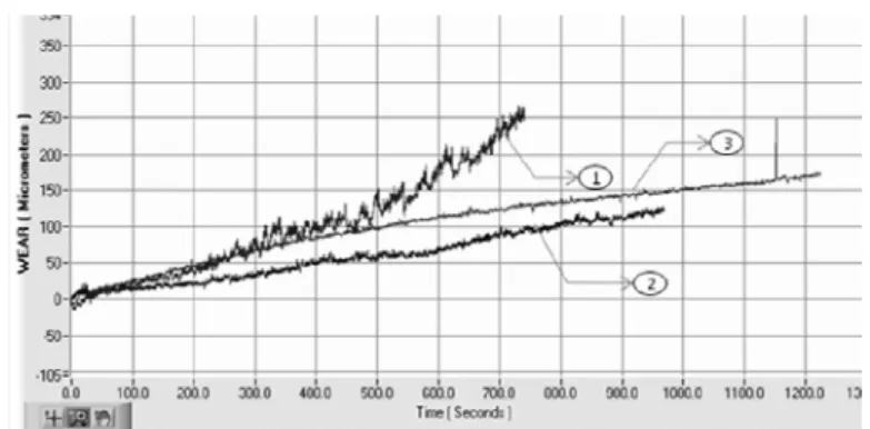
7.5 Wear test results
From the obtained graphs, it can be noted that there is considerable improvement in wear resistance of hybrid composites in comparison with base metal. Hence, it can be successfully used in applications which demand resistance to wear and tear. [Lee C. S., Kim Y. H., et al (1992)] [Basavarajappa Satyappa, Chandramohan Govindarajulu (2005)]
8. Applications of Hybrid Aluminium Composites
9. Conclusion
Present work in the paper unveils that aluminium hybrid composites are successfully produced by Vortex method with 1.25% each and 2.5% each of E-glass fibers and Graphite particles by weight. The macrostructure study reveals the fact that the cast specimens have no porosity and uniform distribution of reinforcement particles. A composite of 2.5% of both E-glass fibres and graphite particles by weight shows substantial increase in hardness and wear resistance in comparison to the one of 1.25% which offers better compressive strength. Scope of this work can be extended, where the percentage of reinforcements in the hybrid composite can be varied to study the individual effect of each reinforcement in a multiple-reinforcement scenario, i.e., percentage of one of the reinforcement can be kept constant while varying the percentage of other reinforcement. A computational model of fiber-particle reinforcement for a metal-matrix hybrid composite would be a step ahead towards understanding the bonding of the multiple reinforcements in a hybrid metal matrix composite [Mahagundappa, M. Benal, Shivanand H.K. (2007)]. In addition, similar experiments can be conducted on other types of reinforcements such as S-Glass, C-glass, silicon carbide etc.
10. References
[1]. ASM Handbook (2000), Vol. 2, pg. 143-167.
[2]. Basavarajappa Satyappa, Chandramohan Govindarajulu (2005), Dry Sliding Wear Behaviour of Hybrid Metal Matrix Composites, ISSN 1392–1320 Material Science, Vol.11, No. 3.
[3]. Brown John R, Foseco Non-Ferrous Foundryman’s Handbook (Eleventh Edition), Foseco International Ltd. [4]. Deteresa et al, Method of Producing a Hybrid Fiber Metal Matrix Composite, (1998) USPTO US 7018578.
[5]. Ejiofor J.U. and Reddy R.G. (1997), Developments in the Processing and Properties of Particulate Al-Si Composites, Journal of Materials Science.
[6]. Lee C. S., Kim Y. H., K. S. Han, T. Lim (1992), Wear Behavior of Aluminium Matrix Composite Materials, Journal Of Materials Science 793800.
[7]. Mahagundappa, M. Benal, Shivanand H.K. (2007), Effect of Reinforcement Content and Ageing Durations on Wear Characteristics of Al (6061) Based Hybrid Composites.
[8]. Specifications of Aluminium Casting Alloy, Hadleigh Aluminium Castings Technology, www.hadleighcastings.com