Anomalous metamagnetic-like transition in a FeRh/Fe3Pt interface
occurring at T ≈ 120 K in the field-cooled-cooling curves for low magnetic
fields
S. Salem-Sugui, A. D. Alvarenga, R. D. Noce, R. B. Guimarães, C. Salazar Mejia et al.
Citation: AIP Advances 2, 032168 (2012); doi: 10.1063/1.4754154
View online: http://dx.doi.org/10.1063/1.4754154
View Table of Contents: http://aipadvances.aip.org/resource/1/AAIDBI/v2/i3
Published by the AIP Publishing LLC.
Additional information on AIP Advances
Journal Homepage: http://aipadvances.aip.org
Journal Information: http://aipadvances.aip.org/about/journal
Top downloads: http://aipadvances.aip.org/most_downloaded
Anomalous metamagnetic-like transition in a FeRh/Fe
3Pt
interface occurring at T
≈
120 K in the field-cooled-cooling
curves for low magnetic fields
S. Salem-Sugui Jr.,1A. D. Alvarenga,2R. D. Noce,3R. B. Guimar ˜aes,4 C. Salazar Mejia,1H. Salim,1and F. G. Gandra5
1Instituto de Fisica, Universidade Federal do Rio de Janeiro, 21941-972 Rio de Janeiro,
RJ, Brazil
2Instituto Nacional de Metrologia, Qualidade e Tecnologia, 25250-020 Duque de Caxias,
RJ, Brazil
3Instituto de Quimica, UNESP, 1801-400, Araraquara, SP, Brazil 4
Instituto de Fisica, Universidade Federal Fluminense, 24210-346, Niteroi, RJ, Brazil
5
Instituto de Fisica, UNICAMP, Campinas, SP, Brazil
(Received 12 March 2012; accepted 31 August 2012; published online 13 September 2012)
We report on the magnetic properties of a special configuration of a FeRh thin film. An anomalous behavior on the magnetisation vs. temperature was observed when low magnetic fields are applied in the plane of a thin layer of FeRh de-posited on ordered Fe3Pt. The anomalous effect resembles a metamagnetic transition
and occur only in the field-cooled-cooling magnetisation curve at temperatures near 120 K in samples without any heat treatment. Copyright 2012 Author(s). This ar-ticle is distributed under a Creative Commons Attribution 3.0 Unported License. [http://dx.doi.org/10.1063/1.4754154]
The Fe1−xRhxsystem withx≈0.5 crystalize in the CsCl structure under certain heat-treatment
conditions.1–3In this cubic phase, equiatomic FeRh is antiferromagnetic and exhibits a metamagnetic magnetostructural phase transition at ambient temperature. The transition temperature is however highly sensitive to small changes out of the equiatomic stoichiometry4and microstructural scale.5,6
The magnetostructural phase transition is of first order kind with a volume expansion of about 1% when entering in the ferromagnetic phase and a temperature hysteresis of the order of 10 K.1,7–9
These characteristics make thin films of the FeRh system to present a good potential for applications as micro-electromechanical devices.10The study which motivated us, performed in the binary thin
film of FePt-FeRh presented in Ref.10, is, in particular, very interesting.
In this work, we study Fe1−xRhxin the compositionx≈0.5 as obtained by electrodeposition on
a foil of ordered Fe3Pt. This work addresses the possibility of obtaining a thin film of FeRh in the
antiferromagnetic phase by electrodeposition on a foil of a ferromagnetic compound, forming a self-sustained film. We chose the ferromagnetic systems to be ordered Fe3Pt, which is a well known and
studied ferromagnet,11,12for which the preparation of a thin foil is quite simple.13The preparation
and study of such a self-sustained film stack, searching for FeRh in the antiferromagnetic phase, was our main motivation. We report here the first results obtained in the film stack Fe3Pt-FeRh prior
to any heat treatment. The system as prepared, presents an anomaly near 120 K in the temperature dependent magnetisation curve when cooled from 300 K, in very low applied magnetic fields. The anomaly appears for fields as low as 20 Oe and it is reproducible, resembling a metamagnetic transition.
The Fe1−xRhx withx≈ 0.5 thin film was obtained by electrodeposition on a 0.6 cm2 of a
thick ordered Fe3Pt film. The electrodeposition occurred in galvanostatic conditions from a bath
composed of: 0.01 Molar Fe2(SO4)3, 0.001–0.0001 Molar Rh2(SO4)3, 0.1 Molar K2SO4 and 0.05
Molar Sodium citrate (Na3C6H5O7). The final film thickness of FeRh falls in the range of 30-50 nm,
depending on the applied current density, which was varied from 1 to 5 mAcm−2, and the charge
for preparing all deposits was kept to 10 C.14–16 An EG-G PAR potentiostat-galvanostat, model
032168-2 Salem-Suguiet al. AIP Advances2, 032168 (2012)
θ
θ
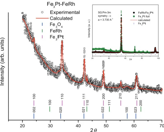
FIG. 1. Low angle XRD of the FeRh face. The Inset shows X-ray diffractions of Fe3Pt and FeRh-Fe3Pt films. Perpendicular
bars appearing below XRD in the main figure and its inset represent the peaks resolved for each correspondent structure.
273, served as a constant current source. The electrodeposition occur under previously established conditions producing an approximately equiatomic deposition of Fe and Rh.14The Fe
3Pt substrate
with≈3μm thickness was obtained by cold-rolling a previously prepared arc-melted sample. The ordered phase of the Fe3Pt foil was achieved after an appropriated heat treatment as described in
Ref.13. A foil with 0.6×0.5 cm2(m=0.00271 g) of the final film was used in the measurements.
Figure1shows a low angle (2 degrees) X-ray diffraction (XRD) curve obtained from the FeRh surface of the film and the inset shows usual XRD curves obtained in the same FeRh surface film and in the Fe3Pt foil used as substrate. It is important to mention that the FeRh structure could not
be resolved by means of usual XRD, as shown in the inset of Fig.1. The double plot in the inset of Fig.1evidences the one-to-one match of the peaks of the ordered Fe3Pt cubic structure in both
diffraction curves. The low angle XRD data was refined for the peaks indicated in Fig.1, following the Rietveld method with the MAUD software17and using ICSD data base. The low angle diffraction curve was obtained about one year after18 the diffraction curve presented in the inset of Fig.1was obtained and, besides the Fe3Pt peaks, it also shows a signal due to Fe3O4, which is absent in the
diffraction curve show in the inset figure. This fact evidences that Fe3O4grew in the FeRh surface
of the film. It should be mentioned that Energy Dispersive X-ray Spectrometry performed on many Fe1−xRhxthin films grown by electrodeposition under same conditions as here did not show oxygen
peaks.14Based on that, one may speculate that Fe
3O4grow on the FeRh surface as a result of surface
oxidation. Despite that, it was possible to identify small peaks in the low angle diffraction curve belonging to the FeRh cubic structure (CsCl type) with lattice parameter a=2.98 Å , as calculated
from the FeRh peaks indicated in Fig.1.
Magnetisation data were obtained by using a PPMS-9T Quantum-Design magnetometer. All data were obtained with the magnetic field applied parallel to the plane of the films. Isofield curves,
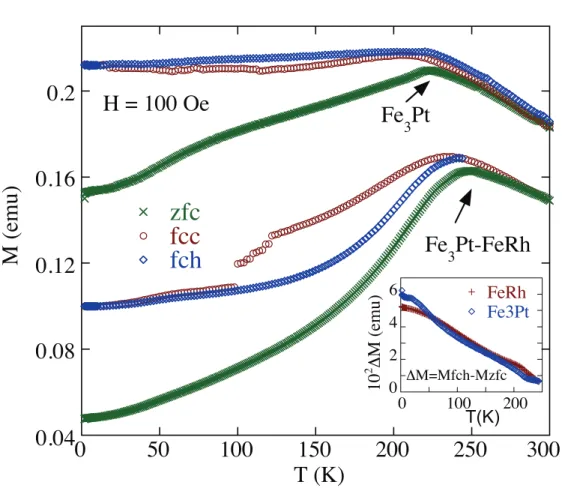
FIG. 2. Magnetisation curves for H=100 Oe for Fe3Pt and FeRh-Fe3Pt films. The inset shows a plot of Mfch-Mzfcvs. T as
obtained for each compound.
300 K, in zero applied magnetic field (zfc), but in the presence of the earth«s magnetic field,
to a desired temperature. After that, for the isofield Mvs.T curves, a magnetic field was applied reaching the desired value without overshooting. The zfc (zero-field-cooled) data was then collected by heating the sample at fixed increments of temperature up to 300 K, which was followed by the fcc (field-cooled-cooling) sequence with sameδTincrements down to 1.8 K. Finally, a fch (field-cooled-heating) process ends the sequence at 300 K. These procedures correspond to a cycle starting with a zfc (zero-field-cooled) curve obtained by heating from 1.8 K up to 300 K followed by a fcc (field-cooled-cooling) curve followed by a fch (field-cooled-heating) respectively. These data were obtained for fields ranging from 20 Oe to 10 kOe. For isothermals Mvs.H curves, magnetisation is measured as the magnetic field increases (or decreases depending on the branch of the hysteresis curve) at fixed increments.
Figure 2displays the Mvs.T curves obtained with a magnetic fieldH=100 Oe applied on a pure Fe3Pt thin foil and on the film stack Fe1−xRhx-Fe3Pt (both films with approximately same
mass). The curves of each system are shifted along the Y-axis for better presentation. Figure2allows the visualization of the overall effect of the thin FeRh layer deposited on the Fe3Pt foil. It is possible
to see that the fcc and fch curves in Fe3Pt are much closer below 200 K than in the film stack. For
FeRh-Fe3Pt, a separation between the fcc and fch curves starts below≈220 K, followed by an
anomaly in the fcc curve appearing as temperature drops below≈120 K, with a jump at 100 K. It is
interesting to observe that both fcc and fch curves for FeRh-Fe3Pt virtually join together below the
jump in the magnetisation at 100 K. One may interpret the anomaly in the fcc curve of the film stack as a metamagnetic transition, similar to that observed in pure FeRh but with a composition out of the equiatomic stoichiometry.4 However, the later can not explain the fact that the fch curve of the
032168-4 Salem-Suguiet al. AIP Advances2, 032168 (2012)
much closer when compared to the large separation of the same curves in the film stack, evidencing the effect of the FeRh layer in the fch curve in the temperature region 100 K–220 K. The same effect seems to explain the reduction in the magnetisation of the zfc curve of the film stack relatively to the zfc curve of Fe3Pt (for Fe3Pt, the reduction in magnetization observed in the zfc curve below
230 K is a consequence of a misalignment of the domains, since as the temperature (or field) is increased the domains become more aligned). The zfc curve of the film stack, which lies well below the correspondent fch curve, also evolves continuously from 1.8 K up to 220 K. To better exemplify this discussion, it is plotted in the inset of Fig.2results of the subtraction between the fch and zfc magnetisation curves of Fe3Pt, and between the fch and zfc curves of FeRh-Fe3Pt (both from Fig.2).
As it is possible to see in this inset, the resulting M =Mfch-Mzfc of each system show quite
similar values and behavior with temperature, highly suggesting that the effect which reduces the fch magnetisation in the FeRh-Fe3Pt film, also reduces the correspondent zfc magnetisation. These
facts may suggest that the deposited FeRh layer has an approximately equiatomic stoichiometry which, if isolated, would show the metamagnetic transition near 220 K. In that case, the anomaly in the fcc curve observed near 120 K when cooling the film in a low magnetic field, as well the continuously increasing of magnetisation observed in the fch curve (and in the zfc curve) when heating the sample from temperatures below the “jump”, might be explained, possibly, in terms of the magnetic coupling between the ferromagnetic Fe3Pt bulk and the antiferromagnetic thin layer
of FeRh. Within this scenarios, the differences between the Fe3Pt and FeRh-Fe3Pt curves of Fig.2
are due to the exchange antiferromagnetic-ferromagnetic coupling, which favor a metamagnetic-like transition occurring near 120 K, only when cooling the film in a fcc curve. It is also interesting to note in Fig.2that, contrary to what occurs for FeRh-Fe3Pt, the fch curve for Fe3Pt lies somewhat
above the fcc curve.
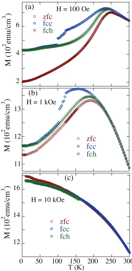
Figure 3 shows isofield curves for FeRh-Fe3Pt sample with H=100 Oe (Fig.3(a)), 1 kOe
(Fig.3(b)) and 10 kOe (Fig.3(c)) (Figure3(a)is the same of Fig.3and it is included here for the sake of comparison). It is possible to see on Figures3(a)and3(b), the anomaly in magnetisation occurring on the fcc curves, whereM starts dropping to lower values (with some apparent discontinuity) as temperature is cooled down below≈120 K. The size, temperature, and width of the anomaly in the
fcc magnetisation curves do not show considerable changes with field. ForH=10 kOe (Fig.3(c)),
the anomalous effect is absent (it is suggestive that this high field overcomes the antiferromagnetic-ferromagnetic exchange coupling) and, interestingly, the zfc curve appears above the fcc and fch curves while the zfc curves in Figs. 3(a) and3(b) appears below the fcc and fch curves. These differences are probably related to the alignment of ferromagnetic domains, which depends on the strength of the magnetic field. As already mentioned, it is interesting to note that, for temperatures above 120 K, the fcc curves in Figs.3(a)and3(b)lie well above the zfc and fch curves, though the fcc curves match almost perfectly the fch curves below 100 K. The later suggest the existence of some antiferromagnetic ordering (within theFeRhthin layer) occurring below 100 K. One may understand this fact as a coexistence of two phases below 100 K, an antiferromagnetic phase due to the FeRh thin layer and a ferromagnetic phase due to the bulk Fe3Pt, which is dominant.
To check for possible effects in the temperature region around 100 K, we plot in Fig. 4(a)
isothermal Mvs.Hcurves obtained from 80 K to 130 K. The main figure shows a 150 Oe window plot of the original M(H) curves presented in the inset. It is possible to see that each curve of Fig. 4(a) exhibit a typical ferromagnetic hysteresis behavior with a perfect symmetric coercive fields. It is also possible to see that the coercive field increases monotonically as temperature decreases.
One should note that the isofieldsMvs.T curves of Fig.3show a maximum in the magnetisation located approximately at 240–250 K. To check for possible effects related to this maximum on
032168-6 Salem-Suguiet al. AIP Advances2, 032168 (2012)
FIG. 4. (a) IsothermalMvs.Hcurves obtained at temperatures around 100 K plotted in a 150 Oe window. The inset shows the originalMvs.Hcurves; (b) IsothermalMvs.Hcurves obtained for several temperatures around 250 K.
FIG. 5. Magnetisation curves as obtained for the FeRh-Fe3Pt film for 100 Oe with 4 months delay.
dependent effect. We also mention that we search for time relaxation effects when in the fcc curve near the anomalous transition above 120 K, but no magnetic relaxation was observed.
Fig.3, the jump is estimated to be≈5 ×10³ emu/cm3 for a 50 nm thickness while the size of the antiferromagnetic-ferromagnetic (AF-F) transition observed in FeRh in Ref.7is of the order of 1.2x10³emu/cm3, but at aT
≈350 K. It should be mentioned that an AF-F transition was observed
in a Fe48Rh52film10atT≈100 K, also with a size of the order of 1.2×10³emu/cm3. So the “size”
of the metamagnetic-like transition observed here for the FeRh-Fe3Pt film appears to be 4 times
bigger than the AF-F transition observed for pure FeRh. This discrepancy might be also in part due to an under-estimative of our FeRh sample thickness. It should be mentioned that an increasing in the FeRh magnetisation above the antiferromagnetic transition has been observed in a FeRh/FePt thin film.10
Figure5depicts two measurements obtained in the same sample at same conditions but with approximately 4 months delay between each other. A comparison of both curves clearly shows the aging effect which shifted the onset temperature of the anomaly to a lower temperature (≈20 degrees below), broadened its width and reduced the size of the apparent discontinuity (by≈30%). We lack, at moment, on an explanation for this aging effect.
In conclusion we obtained a Fe1−xRhx-Fe3Pt withx≈0.5 system by electrodeposition of FeRh
on a Fe3Pt ordered foil. The resulting film stack show, prior to further heat-treatments, an anomaly
in the magnetisation when the sample is cooled in a magnetic field from 300 K down to lower temperatures, after reaching 300 K with the same applied field from a zero-field-cooled heating cycle from 1.8 K. The anomalous magnetisation is reproducible and appears at temperatures close to 120 K, from fields as low as 20 Oe up to fields as high as 1 kOe, and resembles a metamagnetic transition.
SSS, ADA, RBG, and FGG acknowledges support from CNPq and FAPERJ, Brazilian Agencies.
1J. S. Kouvel and C. C. Hartelius,J. Appl. Phys.33, 1343 (1962). 2J. S. Kouvel,J. Appl. Phys.37, 1257 (1966).
3J. M. Lommel and J. S. Kouvel,J. Appl. Phys.38, 1263 (1967).
4O. Kubaschewski,IRON-Binary Phase Diagrams(Springer, Berlin, 1982).
5K. Kang, A. R. Moodenbaugh, and L. H. Lewis,Appl. Phys. Lett.90, 153112 (2007).
6C. Marquina, M. R. Ibarra, P. A. Algarabel, A. Hernando, P. Crespo, P. Agudo, A. R. Yavari, and E. Navarro,J. Appl. Phys.
81, 2315 (1997).
7S. Maat, J. U. Thiele, and E. E. Fullerton,Phys. Rev. B72, 214432 (2005).
8M. R. Ibarra and P. A. Algarabel,Phys. Rev. B50, 4196 (1994).
9M. P. Annaorazov, S. A. Nikitin, A. L. Tyurin, K. A. Asatryan, and A. K. Dovletov,J. Appl. Phys.79, 1689 (1996).
10J.-U. Thiele, S. Maat, and Eric E. Fullerton,Appl. Phys. Lett.82, 2859 7 (2003). 11K. Tajima, Y. Endoh, Y. Ishikawa, and W. G. Stirling,Phys. Rev. Lett.37, 519 (1976). 12E. Kisker, E. F. Wassermann, and C. Carbone,Phys. Rev. Lett.58, 1784 (1987).
13E. E. Alp, M. Ramanathan, S. SalemSugui, F. Oliver, V. Stojanoff, and D. P. Siddons,Rev. Sci. Instrum.63, 1221 (1992).
14R. D. Noce, J. E. de Oliveira, D. R. Cornejo, V. M. T. S Barthem, D. Givord, and A. V. Benedetti, Abstracts of the 61st
Annual Meeting of the International Society of Electrochemistry, (2010), Nice, France.
15I. Tabakovic, S. Riemer, V. Vas’ko, and M. Kief,Electrochim. Acta53, 2483 (2008). 16E. N. Schulz, D. R. Salinas, and S. G. Garcia,Electrochem. Commun.12, 583 (2010). 17L. Lutterotti,Nucl. Instrum. Methods B268, 334 (2010).