CHINA FOUNDRY
366
Vol.9 No.4
Physical modeling of
spent-nuclear-fuel container
Female, born in 1962, professor. Her research interests are mainly focused on fabrication and simulation of heavy section ductile iron. E-mail: [email protected]
Received: 2011-11-22; Accepted: 2012-09-19 *Wang Liping
*Wang Liping1
, Guo Erjun1
, Jiang Wenyong1
, Xue Muyu2
, Liu Dongrong1
and Ren Shanzhi1
(1. School of Materials Science and Engineering, Harbin University of Science and Technology, Harbin 150040, China; 2. School of Materials Science and Engineering, Harbin Institute of Technology, Harbin 150001, China)
T
he ductile iron containers used for store and transportation of spent-nuclear-fuel, which is made by casting process, is designed to withstand both the significant mechanical and thermal loads [1]. Therefore, it is critical to choose the proper casting process and parameters for the production of the container. The container is a heavy-section casting part, and it is difficult and of high cost to investigate and optimize the metallurgy and casting processes on the actual container production scale. Simulation experiments, including both physical and numerical simulations, are necessary and suitable technologies for such challenges. Physical simulation has been widely used for optimizing container casting parameters, which can signiicantly reduce the cost of actual scale experiments [2-3]. Although the importance of physical simulation has been mentioned in many literatures [2-4], the technical details of the simulation have rarely been reported so far. For physical simulation, the basic rule is that the simulated model should be geometrically and physically similar to the actual casting [4-6].In this paper, a specific and detailed physical simulation model is developed for the spent-nuclear-fuel container. Both
Abstract: A new physical simulation model was developed to simulate the casting process of the ductile iron heavy section spent-nuclear-fuel container. In this physical simulation model, a heating unit with DR24 Fe-Cr-Al heating wires was used to compensate the heat loss across the non-natural surfaces of the sample, and a precise and reliable casting temperature controlling/monitoring system was employed to ensure the thermal behavior of the simulated casting to be similar to the actual casting. Also, a mould system was designed, in which changeable mould materials can be used for both the outside and inside moulds for different applications. The casting test was carried out with the designed mould and the cooling curves of central and edge points at different isothermal planes of the casting were obtained. Results show that for most isothermal planes, the temperature control system can keep the temperature differences within 6 ℃ between the edge points and the corresponding center points, indicating that this new physical simulation model has high simulation accuracy, and the mould developed can be used for optimization of casting parameters of spent-nuclear-fuel container, such as composition of ductile iron, the pouring temperature, the selection of mould material and design of cooling system. In addition, to maintain the spheroidalization of the ductile iron, the force-chilling should be used for the current physical simulation to ensure the solidiication of casting in less than 2 h.
Key words: physical simulation; heat transfer; spent-nuclear-fuel container
CLC numbers: TP391.9 Document code: A Article ID: 1672-6421(2012)04-366-04
the physical and geometrical similarities between the actual casting and this model have been investigated. The current model can serve as a valuable tool for optimization of casting process of container.
1 Theory of physical simulation
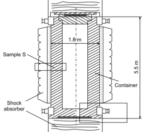
Schematic geometry of QN-X type cast ductile iron spent-nuclear-fuel container is shown in Fig. 1. The container is basically a cylinder tube with diameter 1.8 m and height 5.5
367 Research & Development November 2012
m. A sector portion of the container (Sample S in Fig. 1) was selected to construct the physical simulation model.
Figure 2 shows the simulation casting sample S embedded in the casting mould. The basic dimensions of the physical simulation sample S are LM 390 mm; LO 330 mm; arc PL 445 mm, and arc MQ 330 mm. The dimension of ribs is 285 mm × 235 mm × 20 mm. The difference between the simulation sample S in Fig. 2 and the actual casting container in Fig. 1 is the non-natural surfaces of the simulation sample S, i.e., LMNO, LMQP, QPFE, and ONEF surfaces in Fig. 2. Since the height of the sample S is signiicantly smaller compared with the actual height of the container, the amount of heat loss along the height direction can be neglected. This simpliication may bring some positive deviation for the simulation of solidiication time. In order to ensure the validity of physical simulation, the thermal behavior on surfaces LMNO and QPFE (Fig. 2) should be very close to that in the actual casting.
Fig. 2: Simulation sample S and its isothermal surfaces
(a) Front view of the simulation mould
(b) Top view of the simulation mould
Fig. 3: Schematic of simulation experimental apparatus (mould)
similarity between the physical simulation model and the actual casting.
Changeable mould materials can be used for both outside and inside mould for different applications. In this simulation model, the outside and inside moulds are the green sand mould and the sand coated iron mould, respectively.
Bush of SiC was used to cover the non-natural surfaces of the simulation casting mould. Heating unit was placed outside of the bush to compensate the heat loss. SiC, with the excellent high-temperature mechanical properties and significantly high thermal conductivity (10 to 40 W·m-1
·K-1 at 1,100 ℃) can ensure the stability of the mould and the heat transfer eficiency.
2.2 Design of heating unit
The pouring temperature for the ductile iron spent-nuclear-fuel container casting is around 1,300 ℃. Due to the fact that the time for eutectic reaction is much longer than the solidification time, the heating unit in Fig. 3 should perform a good and stable function in the temperature range from 1,300 ℃ to 1,147 ℃ (eutectic temperature). After a thorough material screening, DR24, an Fe-Cr-Al heating wire was chosen as the heating unit material. With the highest working temperature of 1,400 ℃, and long-time-working A heating unit has to be placed close to the non-natural
surfaces of sample S to compensate the heat loss across these surfaces in order to make the solidiication condition in sample S similar to the actual casting. Two points, i and f, are assigned in the cylinder plane ABCD in Fig. 2. Point i is located inside the sample, and point f is located on the surface LMNO. Upon the pouring of molten alloy into the casting mould in Fig. 2 to form the sample S, the initial temperatures at point i and point f were Tio and Tfo, respectively. Due to the fast mould filling course, it is assumed that Tio is not affected by Tfo at the beginning of casting, so that the variation of temperature at point i is similar to that in the actual casting. During the following solidification process, the cooling rate at point f
should be controlled to keep Tf equal to Ti at any time because that the cylinder surface ABCD should be an isothermal surface. Only in this way can the simulation sample show the physical similarity to the actual casting.
2 Design of mould for physical
simulation
2.1 Design of mould system
CHINA FOUNDRY
368
Vol.9 No.4
Fig. 4: Principle diagram of temperature control system
temperature between 1,200 ℃ to 1,300 ℃, the DR24 heating wire suficiently meet the simulation requirements. Five groups of DR24 heating wire have been used as the heating unit. Geometrical parameters of the heating wires are listed in Table 1.
2.3 Principal of temperature control system
As shown in Fig. 2, during the casting process, the temperature at point f, Tf has to be kept the same as the temperature at point
i, Ti, in order to guarantee that the solidiication process of the
simulation model is similar to that in the actual casting. As shown in Fig. 4, the temperature control system is designed to control the heating unit in Fig. 3 and eventually to make sure Tf
Table 1: Physical parameters of 5 groups of heating wires
Diameter Length Stud length Pitch Winding pitch diameter Power Rated voltage
(mm) (m) (m) (mm) (mm) (kW) (V)
1 2 29.958 4.768 6 12 1.633 152.3
2 2 31.567 5.024 6 12 1.720 160.8
3 2 33.169 5.279 6 12 1.808 168.6
4 2 34.067 5.422 6 12 1.857 173.2
5 2 36.386 5.791 6 12 1.983 185.0
Group
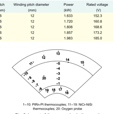
1-10: PtRn-Pt thermocouples; 11-19: NiCr-NiSi thermocouples; 20: Oxygen probe
Fig. 5: Layout of thermocouples in the sample
Vi1
Vf2
Magniier Comparator Relay Heating wire
and sample
Thermocouple 1
Thermocouple 2
is equal to Ti during the whole casting process. Thermocouples 1 and 2 are used to monitor the temperatures Ti and Tf
respectively. The voltage signals issued by the thermocouples 2 and 1, i.e., Vf2 and Vi1 respectively, are sent to a magniier. If Vf2 < Vi1, i.e., Tf < Ti, the comparator will output a negative signal to turn on the relay after receiving the two magniied voltage signals. Subsequently, the heating unit in Fig. 3 starts working to increase Tf until Vf2 > Vi1, i.e., Tf > Ti. Once Tf > Ti, the comparator will output a positive signal to turn off the relay and shut down the heating unit in Fig. 3. This feedback system can accurately monitor and control the thermal behavior of the simulation mould during casting process.
2.4 Temperature measurement
The temperature control system in Fig. 4 has two temperature monitoring sub-systems: the mould temperature monitoring system and the sample temperature monitoring system. As shown in Fig. 5, the sample temperature monitoring system is composed of thermocouples at points 1 to 10 and the mould temperature monitoring system is composed of thermocouples at points 11 to 19. All the thermocouples are inserted from top and extended to the middle height of the simulation mould. The PtRh-Pt type thermocouples in quartz tube are used at points 1 to 10. Figure 5 shows that there are total 5 isothermal planes under temperature monitoring and controlling. Each isothermal plane has two thermal couples, which are located at points 1, 6; 2, 7; 3, 8; 4, 9; and 5, 10 respectively. And each isothermal plane is under one temperature control system as shown in Fig. 4, for example, points 1 and 6 are connected with thermocouple-1 and thermocouple-2, respectively. These 5 temperature control systems can work together to accurately monitor and control the thermal behavior of the physical simulation sample S.
The temperature measurement in the outside mould (sand mould) and the inside mould (sand coated iron mould) provides reference for optimizing the casting parameters. In the outside mould, thermocouples are placed at points 11 to 15 with point 14 at the boundary between outside mould and casting sample. Points 11 to 15 are located with various radial distances away from the mould/casting boundary, which are 100 mm, 150 mm, 200 mm, 0 mm, and 50 mm, respectively. In the inside mould, thermocouples are placed at points 16 to 19. The radial distances between points 16 to 19 and the mould/ casting interface are 50 mm, 20 mm, 120 mm, and 80 mm, respectively. The type of thermocouples inserted in the outside and inside moulds is NiCr-NiSi (diameter 1 mm to 5 mm).
3 Precision of physical simulation
369 Research & Development November 2012
preheating took 3.5 h until the temperature of the casting mould reaches about 600 ℃. In Fig. 5, after preheating the mould and right before the pouring, the temperatures at points 1 to 5 were 530 ℃, 560 ℃, 570 ℃, 585 ℃ and 585 ℃, respectively, and the temperatures at points 15, 11, 12, and 13 were 230 ℃, 80 ℃, 40 ℃ and 40 ℃. Before the pouring process, the temperatures at the point 18 and 19 (Fig. 5) were kept at 24 ℃ and 30 ℃, respectively, so the thermal behavior of the physical simulation is similar to that in the actual casting before pouring according to practices. The cast alloy was melted in a 1.5 t electric furnace and taped at 1,493 ℃.
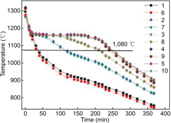
Right after the pouring, the temperature measuring system began to measure the cooling curves at points 1 to 10 in Fig. 2. Figure 6 shows the cooling curves of both central points 1 to 5 and edge points 6 to 10. For most isothermal planes, the temperature differences at the edge points were kept within 6 ℃ with the corresponding center points under the temperature control system. The only exception is point 1 vs. point 6, of which the temperature difference was 10 to 20 ℃ at the beginning of the test due to the air chilling close to point 6. This temperature difference decreased to below 10 ℃ during most of the casting process. Figure 6 shows the temperature control system in Fig. 4 successfully maintains the thermal behavior of surface LMNO similar to the central plane in Fig. 2. It is reported that spheroidalization could be maintained when the heavy section ductile iron is solidified in 2 h, otherwise the spheroidalization decaying will occur [7]. So it is essential that heavy section ductile iron should be solidiied in 2 h. It is found that in Fig. 6, except points 1, 6 and 2, 7, all other points are lower than 1,080 ℃ in 2 h. Therefore, force-chilling should be carried out to conine the solidiication time of the casting within 2 h.
Based on the testing results, the current physical simulation
model is feasible. And the experimental mould designed (Fig. 3) can be used for optimization of casting parameters of the spent-nuclear-fuel container, such as composition of ductile iron, the pouring temperature, the selection of mould material and design of cooling system.
4 Conclusions
A new physical simulation model was developed to simulate the casting process of the spent-nuclear-fuel container, which was characterized with a large cross section and symmetrical geometry. With the use of a precise and reliable temperature controlling/monitoring system, this physical simulation method is designed to make both geometry and the thermal behavior of the simulation casting similar to the actual casting.
The casting test results show that this new physical simulation method does keep the thermal behavior of simulation quite similar to the actual casting process. To maintain the spheroidalization of the ductile iron, the force-chilling should be used for the current physical simulation to ensure the solidiication of casting in less than 2 h.
The experiments show that this new physical simulation method is of high simulation accuracy and the physical simulation mould developed can be used for many basic simulation experiments to optimize casting process and casting parameters of spent-nuclear-fuel container, such as composition of ductile iron, the pouring temperature, the selection of mould and design of cooling system.
References
[1] Nakamura S. As-cast Heavy Section Ferritic Spheroidal Graphite Cast Iron. AFS Transactions, 1989, 97: 539-544. [2] Javaid A, Loper C R JR. Production of Heavy-section Ductile
Cast Iron. AFS Transactions, 1995, 103: 135-150.
[3] Li Z H, et al. Study on Thermal Simulation of Solidiication in Heavy Section Ductile Iron. Journal of Materials Science & Technology, 2003, 19: 122-124.
[4] Sun Wenshan, Liang Weizhong, Liu Jun, et al. A Review of the Study and Application of Heavy Section Nodular Cast Iron. Modern Cast Iron, 1999(3): 5-6. (in Chinese)
[5] Yan Hongying. Study on Preparation and Properties of Magnesium Matrix Composites Reinforced with Silicon Carbon Particles. Master Thesis, Xian University of Technology, 2008: 22-23. (in Chinese)
[6] Zhou Jiyang. Production Technology of Heavy Castings of Nodular Cast Iron in Federal Republic of Germany. Foundry, 1987(11): 1-4. (in Chinese)
[7] Ding Linpu, Lin Rui, Li Jiarong, et al. Effect of Cooling Condition on Solidification Property on Heavy Ductile Iron Casting. Foundry, 1989 (12): 19-22. (in Chinese)
Fig. 6: Cooling curves of different isothermal sections at the edge and in the center of casting
The study was inancially supported by the National Natural Science Foundation of China (Grant Nos. 50974049