CONSIDERATION UPON FIXED ANTI - ROLLING PASSIVE SYSTEMS
Iordan NOVAC1 Catalin FAITAR2 1
Associate Professor Eng., Constanta Maritime University
2
Eng., Constanta Maritime University
Abstract: Tanks anti - rolling Passive Systems, are those systems which have no separate source of movement and no special automatic control system like the Bilge keel, anti – rolling tanks (passive), fixed fins and passive moving weight system. For a vessel, roll motion has the highest amplitude at resonance (this motion is known as synchronous rolling). From the research done so far, the best thing to reduce this movement is increasing amortization. There are many ways to reduce roll motions, and the most known is equipping the vessel with bilge keels. If ship requires more control, there are methods such as anti-roll tanks and fins. Tanks have the advantage of functioning when the ship is not underway. The use of tanks with liquid free surfaces for reducing roll motion of ships is an old concept. Many research engineers have studied the design of anti-roll tanks. However, most of the past research has concentrated on studying the randament of anti-roll tanks in damping the roll motion of the vessel.
Keywords: roll motion, tanks, passive, fin, keel
Introduction
Reducing rolling motion is one of the most desired shipbuilders requirements. Because of this, there are a lot of reductions systems for ships amplitude and movement acceleration that act on its dynamical effect attenuation. In anti - rolling amortization systems study is all important to know forces values applied for getting an emphatic amplitude and acceleration reducing.From all oscillations type (vertical, pitching, rolling, etc.), through this moment can be successfully damped only anti - rolling motion because required moments are small, against the other ones.
For oscillation amortization there are three main type of constrained motion reductions:
• By rising ship amortization factor. This way means a destruction of energy and is referring to free oscillations for resonance area where is maximum effective power. For this category, we have anti - rolling fins and bilge keel.
• By reducing natural frequency of ship and cycle rising. This stabilization type is named ,,according amortization” and is applied only in constrained oscillations where we have a big variation of frequency. • By direct reducing forces and moments of excitation. This stabilization type is named ,,equilibration
stabilization” where applied moment is against perturbation moment. Because of this, the main moment is reduced. Also, stabilization system efficiency depends on the control system.
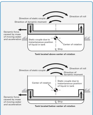
Anti – rolling passive tanks
The use of these tanks was implemented by Frahm in Germany at the start of the 20th century, and they are often referred to as Frahm tanks. These semi filled tanks consist of two wing tanks connected at the bottom by a substantial crossover pipe. The air columns above the liquid in the two tanks are also connected by a pipe. As in the free surface tanks, as the ship starts to roll the fluid flows from wing tank to wing tank causing a time varying roll moment to the ship and with a careful design this rolling moment is of correct phasing to reduce the roll motion of the vessel. They do not restrict fore, and aft passage as space above and below the water-crossover pipe is available for other purposes.
There are several types of roll damping systems that have been developed to reduce a vessel’s roll
motion during operation at sea. Passive roll damping tanks, also referred to as passive anti-roll tanks, use a hydro-dynamically controlled flow of liquid within a specially designed tank, filled with ballast water, to create a stabilizing moment opposing the wave moment that is causing the vessel to roll. The amount of stabilizing moment created depends on several factors, such as size and location of the roll damping tank as well as hull form and loading condition of the vessel. Generally, with a passive roll damping tank an average roll reduction between 40% to 60% can be achieved.
The U-Tank Stabilization System is individually designed for each specific application. A number of tanks, proper dimensions, shape, location, internal structure and volume, are varied to match each type of vessel and operating condition.
260 DOI: 10.21279/1454-864X-16-I2-038
Figure 1. Antirooling passive tanks
The stabilizers are installed on various types of vessels from 20 m up to 400 m length:
• Offshore Support (PSV, AHTS, DSV) vessel • Offshore Construction vessel
• RORO / ROPAX vessel • Container vessel • Research vessel • Pipe Lay vessel • Buoy Tender vessel • Fishing vessel • Naval
A U-Tank Stabilization System is a passive U-tube type anti-roll tank combined with monitoring and an active control system. The stabilizer consists of
two wing tanks interconnected via a crossover pipe either through or above the double bottom and a closed air pipe system including remotely operated valves. The fluid flow within the stabilizer is used to create a stabilizing moment reducing the roll motion of the vessel, hence decreasing roll angles and accelerations. The stabilizer’s dimensions and structural boundaries determine its natural response period which has to be close to the expected shortest roll period of the vessel. A change of the response period is achieved by
restricting the air flow. The system automatically controls the remotely operated valves to adapt the water oscillation period to the measured actual roll period of the vessel.
261 DOI: 10.21279/1454-864X-16-I2-038
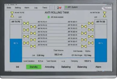
Figure 2. Antirooling passive tanks system
The monitoring and control system has been developed to operate the U-Tank stabilizer safe
and with high efficiency in all operation conditions. The control unit type HOMIP contains the software package for processing of data from the roll sensor unit, the tank pressure sensors, level switches and valve positions. The system
monitors permanently the vessel and tank movement as well pressure and level inside tank to act accordingly roll damping performance and safety. The actual system status is displayed in 6” HOMIP touch screen and on larger touch screens in control cabinet and bridge operation panel.
Figure 3. Antirooling passive tanks control system
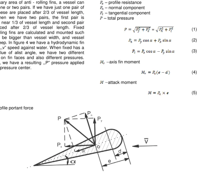
Fixed fins
Fixed fins and bilge keels do not move; they reduce roll by hydrodynamic drag exerted when the vessel rolls. Stabilizers are mostly used on
ocean-going (blue water) vessels. Not only retractable fins but also fixed fins are calculated and are mounted on vessel body like pairs (starboard – port side). Depending on the
262 DOI: 10.21279/1454-864X-16-I2-038
speed on fin faces and also different pressures. Finally, we have a resulting ,,P” pressure applied in ,,O” pressure center.
– profile portant force
axis fin moment
(4) attack moment
(5)
Figure 4. Passive fin forces
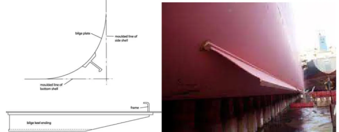
Bilge keel
A bilge keel is a long fin of metal, often in a "V" shape, welded along the length of the vessel at the turn of the bilge. Bilge keels are used in pairs (one for each side of the vessel). A vessel may have more than one bilge keel per side, but this is rare. Bilge keels increase the hydrodynamic resistance when a vessel rolls, thus limiting the amount of roll a vessel has to endure.
On commercial shipping the bilge keel is the form of a strake, or small keel or blister, running along much of the length of the hull. They are typically fitted one on each side, low down on the side of the hull, so as not to increase the draft of the vessel. In warships they were often quite large and used as part of the torpedo protection system.
263 DOI: 10.21279/1454-864X-16-I2-038
Figure 5. Bilge keel
Moving weight system
In a passive system, moving mass makes natural pendulum motions on the arc-shaped rails when the vessel rolls. This generates forces opposing the wave forces to reduce the roll of the vessel. In an active system, the weight is accurately controlled
by electric motors according to information on lateral rolling detected by sensors to reduce the roll of the vessel. The hybrid system combines the features of the pendulum principle (passive system) and electric motor control (active system) to provide excellent roll control for low power expenditure.
Figure 6. Moving weight system
264 DOI: 10.21279/1454-864X-16-I2-038
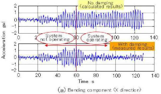
Figure 7. Moving weight system acceleration diagram
Transversal oscillation of a 12000 t vessel
We calculate moment of inertia:
5 2
2
=
12000
⋅
6
=
4
,
32
⋅
10
⋅
∆
=
xxxx
i
I
[tm2] (6)•
∆
=
12000
t
- vessel displacement; •i
xx=
6
m
- the radius of inertia around thelongitudinal axis;
Total moment of inertia with extra vessel mass:
•
1
5
184
10
5
1
=
(
+
f)
⋅
I
xx
=
,
⋅
xx
I
[tm2] (7)•
f
=
15
%
- water extra mass from vessel massFor undamped oscilations we have following coefficients:
Proper pulsation for undamped oscillations:
1
603
,
0
2
6
15
,
1
6
,
1
81
,
9
2
)
1
(
−
=
⋅
⋅
=
⋅
+
⋅
=
s
xx
i
f
T
GM
g
p
ϕ
(8) Period of rolling undamped oscillations:
s
p
T
10
,
425
603
,
0
2
2
=
=
=
π
ϕ
π
ϕ
(9)For damped oscillations is necessary to calculate follows:
Damping factor
υ
ϕ:1
077
,
0
5
10
184
,
5
2
80000
1
2
−
=
⋅
⋅
=
⋅
=
s
xx
I
N
ϕ
ϕ
υ
(10) wheres
tm
N
280000
2
ϕ=
- damping coefficient for navigation in calm water.Pulsation of transversal oscillations, free, undamped:
1
598
,
0
2
2
−
=
−
=
p
s
r
p
ϕ
ϕ
υ
ϕ
(11)
Damped oscillations period:
265 DOI: 10.21279/1454-864X-16-I2-038
s
p
T
r
r
10
,
512
603
,
0
2
2
=
=
=
π
π
ϕ ϕ (12) Logarithmic decrement:
811
,
0
603
,
0
2
077
,
0
2
=
=
⋅
=
∆
π
ϕ
π
ϕ
υ
p
(13)Oscillations amplitude after one period: 0 0 811 , 0 1 0
1
=
=
⋅
15
=
6
,
665
⋅ − ∆ ⋅ −
e
e
A n Aϕ
ϕ
(14)Oscillations amplitude after two period: 0 0 811 , 0 2 0
2
=
=
⋅
15
=
2
,
962
⋅ − ∆ ⋅ −
e
e
A n Aϕ
ϕ
(15) Oscillations amplitude after three period:0 0 811 , 0 3 0
3
=
=
⋅
15
=
1
,
316
⋅ − ∆ ⋅ −
e
e
A n Aϕ
ϕ
(16)At inertial moment (t=0), was banded at
ϕ
0=
15
0, and the initial speed is 0.CONCLUSIONS
From the above observation, it can be concluded that each and every stabilization system has got advantages and disadvantages. Therefore, more amount of effort has to be given to the hydrostatics and the hydrodynamics of the vessel hull motion through the waves, so as to avoid the need for kind of roll stabilization system or to use it to its minimum. Also, in principle methods used to stabilize against roll can be used to stabilize against pitch, but the powers involved are too great to justify their use.
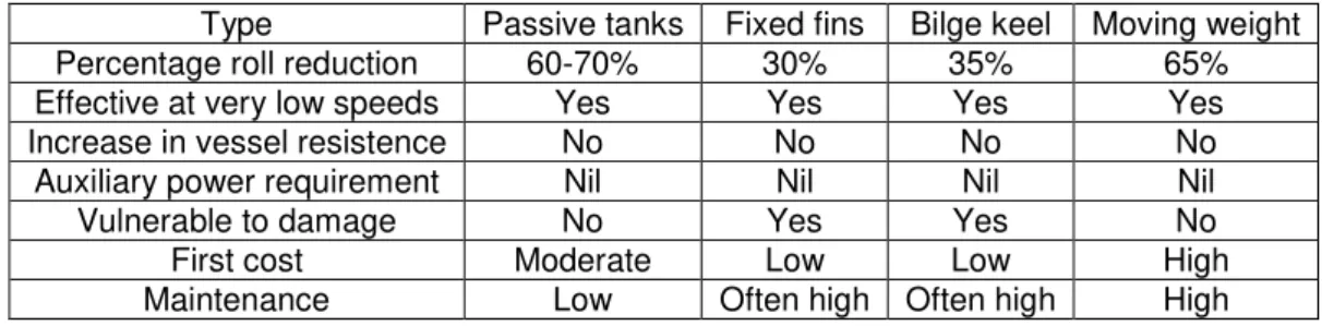
Table 1.Passive anti – rolling system efficiency
Type Passive tanks Fixed fins Bilge keel Moving weight Percentage roll reduction 60-70% 30% 35% 65% Effective at very low speeds Yes Yes Yes Yes Increase in vessel resistence No No No No
Auxiliary power requirement Nil Nil Nil Nil
Vulnerable to damage No Yes Yes No
First cost Moderate Low Low High
Maintenance Low Often high Often high High
BIBLIOGRAPHY
[1] Novac I.Ship theory andconstructionPart2- Ship hydrodynamics1,Constanta Maritime University, 2013 [2] Novac I.Ship theory and construction. Practical problems and guidelines for hydrostatics and
hydrodynamics ship design, Constanta Maritime University, 2013
[3] Kula K.S.An Overview of Roll Stabilizers and Systems for Their Control, Gdynia Maritime University, Poland
[4] Agarwal A. Robust control technology applied to the design of a combined steering/ stabilizer system for warships, 1997
[5] Roberts G.N. Trends In Marine control systems, 2008
[6] www.hoppe-marine.com,U-Tank Stabilization System, Hoppe Korea Co., Ltd. [7] www.deepdyve.com, Ship's roll stabilization by anti-roll active tanks
[8] Moaleji R. and Greig A. Inverse control for roll stabilization on ships using active tanks,2006 [9] Moaleji R. and Greig A. On the development of ship anti‐roll tank,2007.
266 DOI: 10.21279/1454-864X-16-I2-038