Touch Screen based Speed Control of Single
Phase Induction Motor
Sarat Kumar Sahoo #1, W. Razia Sultana *2, S. Mallika #3 #1 *2#3
School of Electrical Engineering, VIT University Vellore-632014, India
1
2
[email protected] 3 [email protected]
Abstract— This paper gives a brief idea of touch screen technology and its interfacing with a controller to control the speed of single phase induction motor. Here touch screen technology and Programmable System on Chip (PSOC) microcontroller concept is utilized which is less space consumption and easy to design. The aim of this paper is to have remote sensing and speed control of an AC motor.
Index Terms— Touch Screen Technology, PSOC, CPLD
I. INTRODUCTION
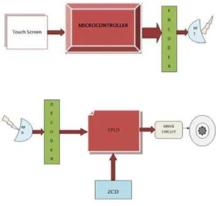
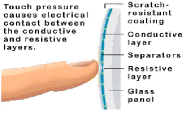
The main aim of this paper is use the touch screen in the speed control system of AC motor and DC motors. In this paper the resistive touch screen, where the user has to physically touch the screen with slight impact on the screen, this variation in the resistance is read by the touch screen controller, this in turns sends the data to the micro controller using the signal conditioning circuit. The micro controller will read the data obtained from the touch screen controller and will decode the message and depending on the data decoded it will perform the specified task of driving the speed of the motor. The software developed in the CPLD will read the data from wireless network and will decode the same, after which it will drive the CPLD unit connected to the SCR control unit, which then drives the motor speed or if the bulb is connected it will drive the intensity of the bulb. The user on touching the screen at particular position the speed of the motor is controlled and like this at different position the different speed is controlled. In this paper the following new technologies are utilized
PSOC microcontroller Touch screen technology
Multiple function processor(CPLD) Wireless control
The motive of this paper is to design an accurate, precise control, less area in memory and easy way of controlling of single phase induction motor.
II. BLOCK DIAGRAM
2.1 Touch Screen
Touch screens are a clear sheet of plastic with tiny sensors that detect pressure from either a finger tip or a pointing device. When these sensors are pressed, they perform, they perform the functions found with the traditional mouse; single
click, double click and drag. A software utility needs to be installed on the computer hard drive to further customize the different settings. Touch screens are great for the cause and effect and software applications that require direct select. Figure 1 show the microcontroller and CPLD based systems.
Fig.1. Microcontroller and CPLD
2.2 Four Wire Resistive Touch screens
Fig.2. Touch Screen
2.3 Interface of 4 Wire Resistive Touch screen with PSOC Although clarity is less than with other touch screen types, resistive screens are very durable and can be used in a variety of environments. This type of screen is recommended for individual, home, school, or office use, or less demanding point-of-sale systems, restaurant systems, etc.
Fig.3. Interface of 4 Wire Resistive Touch screen with PSOC
2.4 Measurement of Touch screen Parameters
Figure 2 shows the touch screen pattern. Now we should know how to use it. To measure the parameters of touch
screen we should interface it with PSOC micro controller. The parameters of Touch Screen are X axis measurement, Y axis measurement and Touch pressure. The circuit diagram of X axis measurement is shown in Figure 5[1].
Fig.4. Touch screen pattern
Fig.5. X- Axis measurement of touch screen
Fig.6. Complete measurement of parameters
position and touch pressure is done. To know more details refer technical document by Cypress [3].
2.5 Detailed Approach of Touch Screen interface with PSOC microcontroller
Necessity of PSOC
Touch screen controller need MUX+PGA (programmable gain amplifier)+ADC
In PSOC MUX+ PGA + ADC are available & they are inbuilt.
In built clock frequency, so no need external crystal.
All these are done with the help of “PSOC designer Software”. Make a LOOK UP table to know the axis of touch screen.
Three requirements of touch screen are 1) X position
2) Y position
3) Touch Pressure Z of both X & Y position The flow chart is as follows
Fig.7. Flow chart to know the axis
To know the axis of Touch screen PSOC is interfaced with LCD. The circuit diagram is as shown in Figure 8 [5]. The
results of the various column and row positions are tabulated in Table 1.
Fig.8. Touch screen and PSOC
TABLE 1
CODE FOR X AND Y POSITION
2.6 Transmission of signal
The above results are coded in the PSOC microcontroller and even programming is done to send the signal from Encoder. HT12E encoder is used. Similarly to receive the signal an decoder is used, here HT12D is used. The advantage of this Encoder and Decoder is it will convert digital data into frequency. Radio Frequency Transmission is used which has 433.3MHz and around 2km of distance.
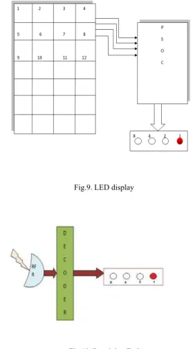
2.7 Testing
Fig.9. LED display
Fig.10. Receiving End
III.CONTROL OF ACMOTOR
In control part Complex Programmable Logic Device (CPLD), Driver circuit and gate pulses design is done. Once output of the decoder is satisfied, it will be interfaced with CPLD. For reset or as oscillator for CPLD, 555 timer is used [6]. The circuit diagram is as shown below Figure 11. As the size and complexity of digital system increases, more and more computer aided design tools are being introduced into the hardware design process. Programmable logic devices provide the benefits of high integration levels without the risks or expenses of IC development. CPLD’S can be designed and verified quickly while the same process requires several weeks with discrete IC’s [10]. These devices being software configured and field programmable. Users can modify their designs very easily. Also there are no, Non-Recurring Engineering (NRE) costs and no delays for prototypes to be manufactured. This results in significant cost savings in design and production. VHDL language is used for programming CPLD [7, 8, and 9]. The design of 555 timers is as follows.
Charging Time = 0.693 * R1R2*C Discharging Time= 0.693 * R2*C Period= 0.693 * (R1 + 2R2) Frequency= 1.44/ (R1 + 2R2) C
R1 =1 KΩ, R2 =10 KΩ, C=0.001µ F Then Frequency= 68 kHz
Fig. 11. CPLD and Timer Interface
IV. GATE PULSE
The gate pulses for the TRIAC circuit are designed by Zero Crossing Detector ZCD circuit. The ZCD circuit is connected to CPLD as shown in Fig 5. When decoder gets position one from touch screen and it send to CPLD, the pulses generated from ZCD will be read by controller and according to coding and number of counter set in the coding the speed will vary. The ZCD circuit is as shown in Figure 12 [4].
Fig.12. ZCD Circuit
Fig.13. Output waveforms of ZCD
V. TRIACCIRCUIT
The TRIAC is known as a component which is essential in controlling power from an AC source (mains). In most cases, the circuit has an inductive component: either because of the nature of the load itself: motors, transformers, ballast inductance; or because of the source impedance: utilization of the secondary of a transformer, length of the supply line, etc. On inductive loads, the operating conditions vary considerably, when closing the circuit, depending on the control mode (gate current, polarity and width) and synchronization of the firing. In order to build an optimal control circuit it is indispensable to analyze the various possibilities. The TRIAC circuit is as shown in Fig ure 7.
Fig.14. TRIAC circuit
The position of the touch screen for various speed of the motor is shown if Table 2. The main advantages of this system are user friendly, no dangers associated with switching, long life, more reliable, consumes less power, easy control of speed and compact in size. The main applications are power cutting
industries, cranes, electric trains and latest application as in washing machines.
TABLE 2
TOUCH SCREEN POSITION
VI. CONCLUSION
In this project we are using Touch Screen in order to control electrical equipments like AC/DC motor, electric bulbs. By making use of this technology, we can control the equipment in a safe and simpler manner. It is easy to operate and can be operated by any one. The danger of electric shock with conventional switches is also eliminated by using technology. The power consumed is relatively low compared to switches. With constant improvement in touch screen technology it would be more feasible to use touch screen than the conventional switches. Use of this type of control would make the systems more reliable and long life.
REFERENCES
[1] Communication - Four-Wire, Resistive-Type Touch Screen with USB
Interface by SVYATOSLAV PALIY.
[2] System level solutions Lab manual, a study on Touch Screen by JOHN
J ROVE.
[3] Edusat Programme lecture notes on power electronics by Prof. M.
Madhusudhan Rao.
[4] Zero Crossing Detectors by SUNPLUS.
[5] Technical Reference by PSoC Cypress.
[6] Timer Circuits by John Hewes 2008.
[7] “Architecture of FPGAs and CPLDs: A Tutorial”, Stephen Brown and
Jonathan Rose Department of Electrical and Computer Engineering University of Toronto
[8] VHDL Tutorial “Jan Van der Spiegel” University of Pennsylvania
[9] A VHDL Primer- American Telephone and Telegraph Company Bell
Laboratories Division by Jayaram Bhasker
[10] Designing with XC9500 CPLDs by Xilinx Inc.
TOUCH SCREEN POSITION
SPEED IN RPM
OUTPUT VOLTAGE IN VOLTS
1 190 73
2 245 117
3 350 199
4 600 207
5 774 211