S. K. Sinha / International Journal of Engineering Science and Technology Vol. 2(12), 2010, 7616-7618
AUTOMATING FACING OPERATION
ON A CNC MACHINING CENTRE
S. K. SINHA
Department of Mechanical Engg. Institute of Technology, Banaras Hindu University
Varanasi-221005, India E-mail : [email protected]
Abstract
Facing is usually the first and an essential process on a CNC machining centre, using a face-milling cutter, on any workpiece, because many a time, the workpiece is obtained through a “rough” casting process. The advantage of a cast part is that a workpiece with slightly oversize dimensions is made available, usually requiring very little machining. This saves machining costs. However, the inherent limitation of common casting processes is inaccuracy in dimensions as well as surface roughness. Because of this reason, facing becomes the first machining operation. On a CNC milling machine, this requires a facing program written in terms of G-codes. Since dimensions of different workpieces are likely to be different, offering different areas to be faced, the same program would not work on all workpieces. The present paper uses the latest macro-programming technique, available on modern CNC machines, to develop a single program for workpieces of all dimensions.
Keywords
CNC; G-codes; Macro programming; Custom Macro B
1. Introduction
Machining, casting and forging are the most common manufacturing processes. Each technique has its own advantages and limitations. For example, casting produces the weakest part whereas the strongest part is produced by forging. However, an advantage with casting is that it is less expensive than a forging process, Moreover, machinability of a cast part is extremely good. Therefore, in applications where too much strength is not a criterion, casting becomes the first choice. However, inaccuracy in dimensions, along with surface roughness, is the inherent limitation of a cast part. Hence, usually a cast part invariably requires some machining, often facing being the first one.
When it comes to a facing operation, a G-code program can be written, mostly involving rapid traverse (G00) and linear interpolation (G01). Though the actual program does depend on the control being used on the machine, in a simple case such as this, the program would be essentially same for all the controls, because all control manufactures use the same basic program codes, such as G00 for rapid traverse, G01 for linear interpolation, G02 for clockwise circular interpolation, G03 for counterclockwise circular interpolation, and so on [1, 2]. Therefore, while program portability is not really a problem, one does have to write a new program for every new workpiece, because of difference in facing area/geometry. Moreover, since a CNC machine is pretty expensive, one has to first prove a program before actually executing on the machine. Writing a program, followed by proving it meticulously, is a time taking process. And if the services of an expert programmer are not readily available, the company has to look for a suitable person, many a time from outside the company. This not only increases the production cost, but also affects productivity adversely. Therefore, it is desirable to have a ready-made program which could be used for workpieces of all dimensions. The aim of the present paper is to develop such a general-purpose program.
2. Existing Solution
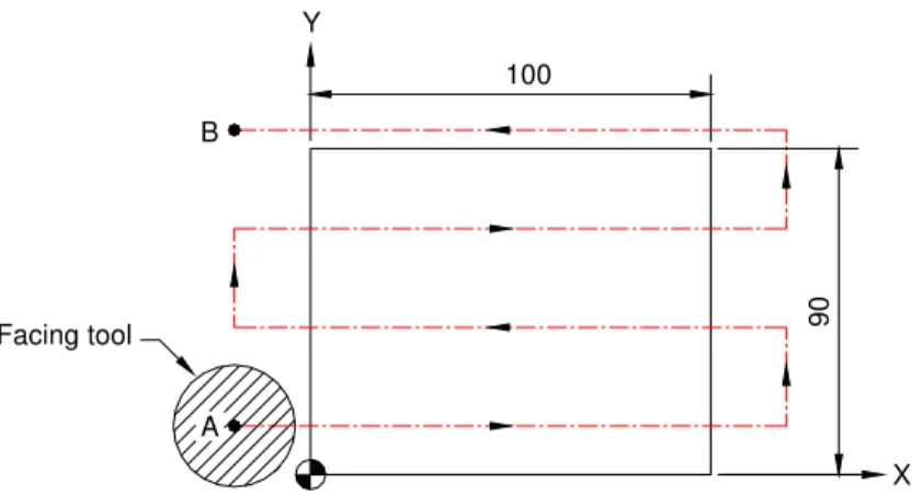
As discussed, separate programs for workpieces of different sizes need to be written. For example, consider facing operation on a workpiece of 100 mm x 90 mm size, with a facing tool of 30 mm diameter. With the lower left corner of the top surface selected as the program zero point, and using an overlap/clearance of 2 mm in cutting passes, the following program can be written, which initially places the tool at position A and follows the shown toolpath to reach position B in the end (see Fig. 1):
O0001; Program number
G21 G94; Millimeter mode and feed in mm/min selected
G91 G28 Z0; Z-homing
G28 X0 Y0; XY-homing
M06 T01; Tool change
S. K. Sinha / International Journal of Engineering Science and Technology Vol. 2(12), 2010, 7616-7618
100
X Y
A B
Facing tool 90
Fig. 1: Facing operation on a rectangular plate
G90 G00 G43 H01 Z200; Tool placed 200 mm above the workpiece
X-17 Y13; Tool placed at A (using 2 mm clearance)
Z2; Tool placed 2 mm above the workpiece, at position A
M03 S500; Spindle starts with 500 clockwise rpm
G01 Z-0.5 F60; Facing depth assumed to be 0.5 mm
G91 X134; First facing pass
Y28; Positioning for second facing pass
X-134; Second facing pass
Y28; Positioning for third facing pass
X134; Third facing pass
Y28; Positioning for fourth facing pass
X-134; Fourth facing pass, to reach position B
G00 Z200; Tool retracts, after facing is complete
M05; Spindle stops
M30; Execution ends and control resets
While there is nothing wrong with this program which will do the required facing without any problem, the fact remains that this is a specific program for a specific job. If there is any change in the workpiece dimension, a new program would need to be written. This would be a time-consuming process, since the programmer will have to do all the calculations again, and verify the new program by meticulously analyzing its simulation. Moreover, services of an expert programmer may not be available all the time.
4. Proposed Solution
The author presents a general-purpose program, using the latest macro-programming technique available on modern CNC machines [3, 4], which can face workpieces of any dimension, without making any change in the program. This program would need to be stored as a macro in the CNC memory, which may be called by any program needing facing. Instead of fixed values, the macro has been developed in terms of variables, the initial values of which are passed on to the macro, from the calling program, using the macro-call code G65. The tool number and the offset number of the facing tool, and spindle rpm would need to be specified in the main program (the macro-calling program), though it is possible to make the macro even more general by using variables for these also, inside the macro. The specific language for writing the program is Fanuc Custom Macro B. For other controls, minor changes in the program might be needed; the basic structure of the program would remain unchanged. For using this program, the machine-table should be made datum for Z-axis. X/Y datum can be placed at any convenient location. After clamping the workpiece onto the table, one would need to measure the coordinates of the lower left corner, as well as the thickness (Z-coordinate) of the workpiece.
List of variables used in the macro:
Length (X-dimension) of workpiece, A #1 Width (Y-dimension) of workpiece, B #2 Overlap in facing passes, C #3 Facing tool diameter, D #7
Depth of cut, E #8
Facing feedrate in mm/min, F #9 Lower left corner X-coordinate #24 Lower left corner Y-coordinate #25
S. K. Sinha / International Journal of Engineering Science and Technology Vol. 2(12), 2010, 7616-7618
Z-coordinate of top surface of workpiece #26
Main program:
O0002; Program number
G21 G94; Millimeter mode and feed in mm/min selected
G91 G28 Z0; Z-homing
G28 X0 Y0; XY-homing
M06 T01; Desired tool placed in the spindle
M03 S500; Spindle starts with the desired clockwise rpm G90 G00 G43 H01 Z200; Tool positioned at a safe height above the table G65 P8000 A100 B90 C2 D30 E0.5 F60 X0 Y0 Z0; Macro call for dimensions/parameters of Fig. 1 G00 Z200; Tool retracts, after facing is complete
M05; Spindle stops
M30; Execution ends and control resets
Macro:
O8000; Program number (the so-called macro)
#100 = #2 + 2 * #3; Required facing width calculated, including clearance G90 G00 X[#24 - #7 / 2 - #3] Y[#25 + #7 / 2 - #3]; Tool placed at A (using the clearance specified in #3) Z[#26 + 2]; Tool positioned 2 mm above the workpiece, at position A G91 G01 Z[- 2 - #8] F#9; Tool brought down to the specified facing depth
X[#1+ #7 + 2 * #3]; First facing pass
#100 = #100 - #7; Remaining facing width calculated IF [#100 LE 0] GOTO 10; Jump to end if facing is complete G00 Y[#7 - #3]; Lateral shift for the next facing pass #101 = -1; Index for altering direction of facing
WHILE [#100 GT 0] DO 1; Execution in a loop till the entire width is faced
G01 X[#1 + #7 + 2 * #3] * #101; Next facing pass, in a direction opposite to the previous facing pass
G00 Y[#7 - #3]; Lateral shift for the next facing pass #100 = #100 - #7 + #3; Remaining facing width calculated #101 = #101 * [- 1]; Sign of facing-direction index reversed
END 1; End of loop
N10 G90 G00 Z[#26 + 2]; Z-retraction to 2 mm above the workpiece
M99; Return to the calling program
5. Conclusion
Using the latest macro-programming technique available on high-end CNC machines, a general facing program was developed which can be used to face workpieces of all dimensions, without incurring any extra cost or compromising in quality. Such an approach results in increased efficiency of the manufacturing system, since the enormous time consumed in developing and proving new programs is saved [5]. Manufacturing industry needs such general-purpose programs for cutting manufacturing costs, in view of cut-throat competition in manufacturing sector these days.
References
[1] Sinha, S. K., “CNC Programming (eighth edition),” Galgotia Publications Private Limited, New Delhi. [2] Smid, Peter, “CNC Programming Handbook (third edition), Industrial Press Inc., New York.
[3] Sinha, S. K., “CNC Programming using Fanuc Custom Macro B,” McGraw-Hill Professional, New York. [4] Smid, Peter, “Fanuc CNC Custom Macros,” Industrial Press Inc., New York.
[5] Djassemi, Manocher, “A Parametric Programming Technique for Efficient CNC Machining Operations,” 23rd International Conference on Computers and Industrial Engineering, pp. 33-36.