Prediction of Chatter in CNC Machining
based on Dynamic Cutting Force for Ball End
Milling
R. Daud, N.K.Hasfa, S.H.Tomadi, M.A.Hassan,K.Kadirgama, M.M.Noor, M.R.M.Rejab
Abstract: This paper presents the suitable depth of cut, spindle speed and feed rate that will be chosen during machining. If thus parameters are not considered, this can provoke abnormal tool behavior such as chatter. Chatter will limit the tool life which only can be use for just a few times. To predict the chatter occurs, the parameters will be use are spindle speed, depth of cut and feed rate. CNC machine will be use. This process will base on dynamic cutting force model for ball end milling. The selections of cutting tool are depends on the process that will done where the chatter can be observed during this machining process. Cold work tool steel (AISI-D2) chosen as a material and its parameter is 100x100x25 mm. Cutter used was high speed steel 2 flute ball nose. Force dynamometer will be use to measure force and 27 tests will be done to observe the chatter occur. Analysis done by referring the result that be measured by force dynamometer. The chatter in ball end milling can be detected from the calculated cutting forces and their frequency spectra. A comparison of the predicted and measured cutting forces demonstrated that the proposed method provides accurate results.
Keywords: Chatter, Dynamic Cutting Force Model, Kiestler Dynamometer
I. INTRODUCTION
The metal cutting technology growth rapidly and has enrolled as important aspect in manufacturing industry especially for aerospace industry and also in producing high precision part. In modern cutting technology, the trend continues unabated toward higher availability with more flexibility. Milling is the most important and widely useful operation process for material removal compared to turning, grinding and drilling. Milling can be defined as machining process in which metal is removed by a rotating multiple-tooth cutter with each tooth removes small amount of metal in each revolution of the spindle.
1Faculty of Mechanical Engineering,
Universiti Malaysia Pahang, Lebuhraya Tun Razak, 26300, Kuantan, Pahang, Malaysia.
Phone: +6095492220; Fax: +6095492244 Email: rosdidaud@ump.edu.my
A machine tool directly influences the quality, productivity, and competitiveness of various production processes found in the automotive, aerospace, and die/mold industries [1, 2, 4 and 12]. To maximize the productivity in a machining process, both the speed at which the tools can machine without causing deterioration in the stability of system and accurate evaluations of machining stability are crucial [2].
The cutting process is given a great deal of weight in the development and production of products. Therefore, reducing the time required for the cutting process is one of the most effective methods of achieving rapid product development and improving productivity. The cutting speed must be increased to reduce the machining time, but this can provoke abnormal tool behavior such as chatter, which it is the most critical problems in the cutting process [1].
II. LITERATURE REVIEW
Chatter is an abnormal tool behavior which it is one of the most critical problems in machining process and must be avoided to improve the dimensional accuracy and surface quality of the product [1, 2 and 4]. Its causes excessive tool wear, noise, tool breakage, and deterioration of the surface quality, it is essential to detect and prevent its occurrence. A varied uncut chip thickness in the cutting process induces variations in the cutting force, which repeatedly induce tool vibration. This phenomenon is called the regenerative effect and is a major source of chatter [1]. The end milling process is characterized by an interrupted cutting process in which the uncut chip thickness varies continuously. A varied uncut chip thickness in the cutting process induces variations in cutting forces, which repeatedly induce tool vibrations. This phenomenon is called the regenerative effect and is major source of chatter [1].
to improvements in cutting performance. An understanding of chatter theories in milling cutters helps in recognizing dangerous cutting operations, optimizing the cutting parameters to eliminate chatter, and enhancing productivity [1 and 7]. The reflex to slow down the cutting process when chatter is audibly recognized can be detrimental to a cutter, especially when dealing with high velocity machining. In many cases, as this report will show, speeding up the cutting process may reduce or eliminate chatter most effectively. Developed an improved an uncut chip thickness model to consider the back-side cutting effect in unstable cutting states. Experimental results demonstrate that the chatter was predicted effectively by the developed dynamic cutting force model [1, 12, 13 and 14].
A Dynamic cutting force
In general, a cutting process is a closed loop system consisting of structural dynamics and cutting dynamics, and the chatter arises from the interaction between two dynamics. In other words, the relative displacement between the tool and workpiece brings about variations in the cutting forces due to the cutting dynamics, and the varied cutting forces bring about variations in the relative displacement due to the structural dynamics. An accurate cutting force model of ball-end milling is essential for precision prediction and compensation of tool deflection that dominantly determines the dimensional accuracy of the machined surface [1 and 15].
The modeling of cutting forces is often made difficult by the complexity of the tool/workpiece geometry and cutting configuration. Analytical cutting force is difficult due to the large number of interrelated machining parameters. The large number of interrelated parameters that influence the cutting forces (cutting speed, feed, and depth of cut, cutter geometry, and tool wear, physical and chemical characteristics of the machined part) makes it extremely difficult to develop a proper model.
Researchers [3], [4], [5] and [6] have been trying to develop mathematical models that would predict the cutting forces based on the geometry and physical characteristics of the process. However, due to its complexity, the milling process still represents a challenge to the modeling and simulation research effort.
Most previous research estimated the stability in flat end milling using only a simple tool path, such as a single line or corner paths. However, the calculation of dynamic forces in multi-tool paths must be performed to predict chatter in general NC machining operated by an NC code.
To calculate the dynamic cutting force in ball end milling, a structural dynamic model of the ball end
mill was linked to a mechanistic cutting force model. Cutter runout and penetration effects were also considered in our models to permit a more accurate evaluation of the machining [1].
Figure 1.1: Cutting force model
III. EXPERIMENTAL METHOD
The prediction of stable cutting regions is a critical requirement for milling operations. In order to achieve the aim and objectives of this research, a sequence of works have been planned as shown in (Figure 3.1) below. The process involved in achieving notified objectives are including determining apparatus, method and parameters, conducting machining/experiment, result analysis and data discussion. The result obtained from the research will be applied in identifying significant and insignificant parameters to chatter occurrence.
Figure 1.2 Procedure flow diagram. Determine Material, Method and Machining Parameters
MACHINING / EXPERIMENT
RESULT ANALYSIS
Data Discussion and Conclusion of Paper
NO Repeat the process
A Table of Experiment
To build an experiment table, a lot of source and formulae are referred to get the number of test for this experiment and finally get 27 tests.
Table 1: Table of Experiment. Test
no.
Total Depth of cut, dw (mm)
Feed rate,f (mm)
Spindle speed RPM (rev/min)
1 3 300 1000
2 3 300 2000
3 3 300 3000
4 4 300 1000
5 4 300 2000
6 4 300 3000
7 5 300 1000
8 5 300 2000
9 5 300 3000
10 3 400 1000
11 3 400 2000
12 3 400 3000
13 4 400 1000
14 4 400 2000
15 4 400 3000
16 5 400 1000
17 5 400 2000
18 5 400 3000
19 3 500 1000
20 3 500 2000
21 3 500 3000
22 4 500 1000
23 4 500 2000
24 4 500 3000
25 5 500 1000
26 5 500 2000
27 5 500 3000
For this experiment, about 27 tests are done to observe chatter occur by using dynamometer which it’s detect rapidly increase force value during machining. When this happened, the chatter has occurs on that time.
Calculation for number of test:
Spindle speed values = 31 = 3 Feed rate values = 31 = 3 Depth of cut values = 31 = 3
Total number of test = 3x3x3 =27 tests.
B Material Cutting Designation
Cold work tool steel was considered as the workpiece. As the cutter tools material, High-speed steel (HSS) have become among the premier choices beside Solid Carbide and Coated Carbide cutter tools.
Even though both Solid and Coated Carbide have better hardness and can undergo higher cutting speed and material removal rate without fracture, but HSS cutter tools are more effective due to high resistance of softening effects of heat in which they are capable to attain a high hardness at elevated temperature. Moreover, HSS has less distortion in heat treatment and also, they are less expensive if compared on prices with both Carbide cutter tools.
The preferred method of milling operation of our experiment is slot milling. Research will be carried on using CNC machine. So, developing any G-codes are required.
In this experiment depth per cut for every cutting process is 0.5mm. The cutting process will be run with depth per cut of 0.5mm until get the total depth of cut needed. During cutting, the Force Dynamometer will connect to get the result and the graph in x, y and z axis. The data will take during cutting process. Figure 3.3 shown below illustrated CAD design on how workpiece will be set up for chatter vibration analysis.
Figure 1.3: CAD design of workpiece for machining
IV. RESULTS AND DISCUSSION
A Preliminary Finding Research
B Result of Cutting Forces
The result gained from force dynamometer came in four different outputs which is cutting force in x, y and z direction (Fx), (Fy), (Fz) and moment in z-direction (Mz). However, only a cutting force in x-axis, (Fx) and y-x-axis, (Fy) will be considered to be analyzing as these two function enrolled the major part in causing the chatter. By using Kitsler® Dynoware, the x-axis and y-axis force reading for milling is gather and being converted directly into force-time graphical figure where it is much better to understand compared to the raw data obtained. Then, a mean value of each graph is taken as these data will be used in identifying significant factor in chatter occurrence. Table 4.1 below illustrated all the data attained from previous 27 experiments.
Table 1.2: Cutting force in x, y-direction.
No
of
Test Depth
of Cut
(mm) Feed
rate
(mm/mi
n)
Spind
le
Speed
(rpm)
Fx (N) Fy (N)
1 3 300 1000 952.63 920.04
2 3 300 2000 926.88 914.04
3 3 300 3000 940.18 890.5
4 4 300 1000 1007.57 939.33
5 4 300 2000 1002.85 928.89
6 4 300 3000 1001.27 918.75
7 5 300 1000 3237.94 2964.04
8 5 300 2000 815.31 854.74
9 5 300 3000 761.56 945.02
10 3 400 1000 834.26 897.66
11 3 400 2000 785.65 934.01
12 3 400 3000 71.41 20.14
13 4 400 1000 643.18 865.62
14 4 400 2000 708.24 934.66
15 4 400 3000 924.32 879.18
16 5 400 1000 843.5 915.04
17 5 400 2000 849.9 927.25
18 5 400 3000 840.33 926.27
19 3 500 1000 792.72 885.99
20 3 500 2000 836.36 910.52
21 3 500 3000 823.61 907.84
22 4 500 1000 826.78 909.91
23 4 500 2000 855.95 929.69
24 4 500 3000 854.12 932.98
25 5 500 1000 834.35 886.35
26 5 500 2000 796.25 885.62
27 5 500 3000 794.55 909.3
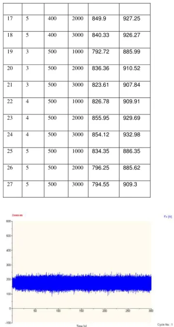
Figure 1.4: Cutting force Fx (N) versus time (s)-test 1.
Figure 1.5: Graph cutting force Fx (N) versus Time
(s)-test 7.
Figure 1.5 show the cutting force Fx (N) versus time (s) which the parameters are 5mm depth of cut, 300mm/min feed rate and 1000rpm spindle speed. As shown in the graph, the force rapidly increased from constant to high value of force. It shows that high vibration happened and therefore onset of chatter.
Figure 1.6: Graph cutting force Fy (N) versus Time
(s)-test 7
Figure 1.6 show cutting force Fy versus time. In this graph, the constant force extremely increased to the high value. It shows that chatter was occurred on that time. This happened when the vibration so extreme and its make the cutter vibrate to fast and let the chatter to occur. During this experiment, the parameters are 5mm depth of cut, 300mm/min feed rate and 1000rpm spindle speed.
Figure 1.7: Graph cutting force Fx (N) versus Time
(s)-test 27
Figure 1.7 show the cutting force Fx versus time. In this graph the cutting force Fx increased rapidly on 56.649s. On that time, the chatter was occurred. The parameters for this graph to obtain are, 5mm depth of cut, 500mm/min feed rate and 3000rpm spindle speed.
Figure 1.8: Graph cutting force Fy (N) versus Time
(s)-test 27
C Discussion on graph from Kitsler® Dynoware
As we can see from figures above, chatter only occurred in test 7 and test 27. In test 7 which shown in Figure 4.5, the parameters needed to run this experiment are 5mm depth of cut, 300mm/min feed rate and 1000 rev/min spindle speed.
Based on the graph, it show that when run the experiment with too deep depth which is 5mm and the feed rate and spindle speed was too slow, it will let chatter to occurred. It shows that, during milling process, it must have a good combination for thus three parameters. But in this test 7, chatter occurred a bit slower then test 27. Which in test 7, the chatter occurred on 126.85s. Compared with test 27 where the chatter occurred on 56.659s and faster then test 7. This is because, when the depth of cut is too deep, spindle speed and feed rate was too fast, it will let chatter to occurred very fast. It also let the cutter damage very
We can see that dept of cut influence chatter to occur. When the depth of cut is too deep, the spindle speed and feed rate should not too fast and too slow. So that, it should have suitable parameters to run the cutting in milling according to material that need to cut.
V. CONCLUSION
This paper is successfully completed and all of the noticed objectives already been achieved which are to predict the chatter occurrence of end milling by using ball end mill cutter. The cutting forces of mild steel machining was successfully obtained by Kitsler® Force dynamometer. From the graph obtained by Kitsler® force dynamometer, it’s obviously showed that, the most significant factor for the chatter occurred is depth of cut and spindle speed. As we can see from the graph obtained by Kitsler®, the depth which is 5mm gave chatter to occur.
Even though the spindle speed and feed rate was slow, the depth of cut should not too depth. So, this will avoid chatter to occur. A commonly used method for avoiding chatter vibrations in machining is to select low spindle speed and small depth of cut.
REFERENCES
[1] Seon-Jae Kim, Han Ui Lee and Dong-Woo Cho, Prediction of Chatter in CNC machining based on dynamic cutting tool for ball end milling, sciences direct.
[2] S.J. Kang, D.W. Cho and C.K. Chun, Evaluating stability of a transient cut during end milling using the dynamic cutting force model, International Journal of Precision Engineering and Manufacturing 1 (2) (2000), pp. 67–75.
[3] Instantaneous shear plane based cutting force model for end milling, Journal of Materials Processing Technology, Volume 170, Issues 1-2, 14 December 2005, Pages 164-180, Chu-Hsiang Chiou, Min-Sung Hong and Kornel F. Ehmann
[4] Prediction of chatter in high speed milling including gyroscopic effects, International Journal of Machine Tools and Manufacture, Volume 46, Issue 9, July 2006, Pages 996-1001, Mohammad R. Movahhedy and Peiman Mosaddegh
[5] T. Insperger, G. Stepan, P.V. Bayly and B.P. Mann, Multiple chatter frequencies in milling process, Journal of Sound and Vibration 262 (2003), pp. 333–345.
[6] Predictive force model for ball-end milling and experimental validation with a wavelike form machining test, International Journal of Machine Tools and Manufacture, Volume 46, Issues 3-4, March 2006, Pages 367-380, M. Fontaine, A. Devillez, A. Moufki and D. Dudzinski
[7] Uncharted islands of chatter instability in milling, International Journal of Machine Tools and Manufacture, Volume 48, Issue 1, January 2008, Pages 124-134, B.R. Patel, B.P. Mann and K.A. Young
[8] T. Insperger, G. Stepan, P.V. Bayly and B.P. Mann, Multiple chatter frequencies in milling process, Journal of Sound and Vibration 262 (2003), pp. 333–345.
[9] H.U. Lee and D.W. Cho, Intelligent feedrate scheduling based on virtual machining, International Journal of Advanced Manufacturing Technology 22 (2003), pp. 873–882.
[10] J.H. Ko and D.-W. Cho, 3D ball-end milling force model using instantaneous cutting force coefficients, Journal of Manufacturing Science and Engineering 127 (2005), pp. 1–12.
[11] F. Abrari, M.A. Elbestawi and A.D. Spence, On the dynamics of ball end milling: modeling of cutting forces and stability analysis, International Journal of Machine Tools and Manufacture 38 (3) (1998), pp. 215–237.
[12] Prediction of regenerative chatter by modelling and analysis of high-speed milling, International Journal of Machine Tools and Manufacture, Volume 43, Issue 14, November 2003, Pages 1437-1446, R. P. H. Faassen, N. van de Wouw, J. A. J. Oosterling and H. Nijmeijer
[13] Multisensor approaches for chatter detection in milling, Journal of Sound and Vibration, Volume 312, Issues 4-5, 20 May 2008, Pages 672-693, E. Kuljanic, M. Sortino and G. Totis
[14] S. K. KIM and S. -Y. LEE , Chatter prediction of end-milling a vertical machining center, Journal of Sound and Vibration, Volume 241, Issue 4, 5 April 2001, Pages 567-586.